Week-7 : Converting a detailed engine model to a FRM model
Aim:
- To Explore tutorial number 9 and write a detailed report
- To Build FRM Model for following configuration using FRM builder approach
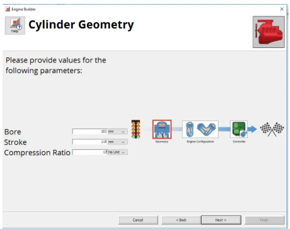
- Bore 102 mm stroke 115 mm CR 17
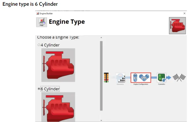
- No of cylinder 6
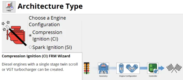
- CI engine
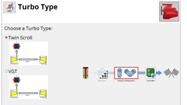
- Twin Scroll Turbine
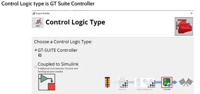
- GT Controller
- To Run all cases
Theoritical Background:
FRM stands for Fast Running Model. When the speed of the run is important we require FRM. When we want to solve transient cycles where cycle time is very high we can't afford to run very detailed model. FRM models are Fully Physical, Dynamic and Designed to run fast. The mean value is no feasable and we cannot capture the in cylinder pressure which require more data and Statistics involved. In case of Fast Running Approach we can retain physical approach and also get good accuracy.
FRM are able to achieve such fast run times by 2 means
- Increasing the simulation time step size
- Decreasing the number of calculations per time step
In FRM there are two approaches
FRM Converter - helps to convert the detailed model in to FRM
FRM Builder - FRM is built from scratch using FRM tool
Tutorial 9
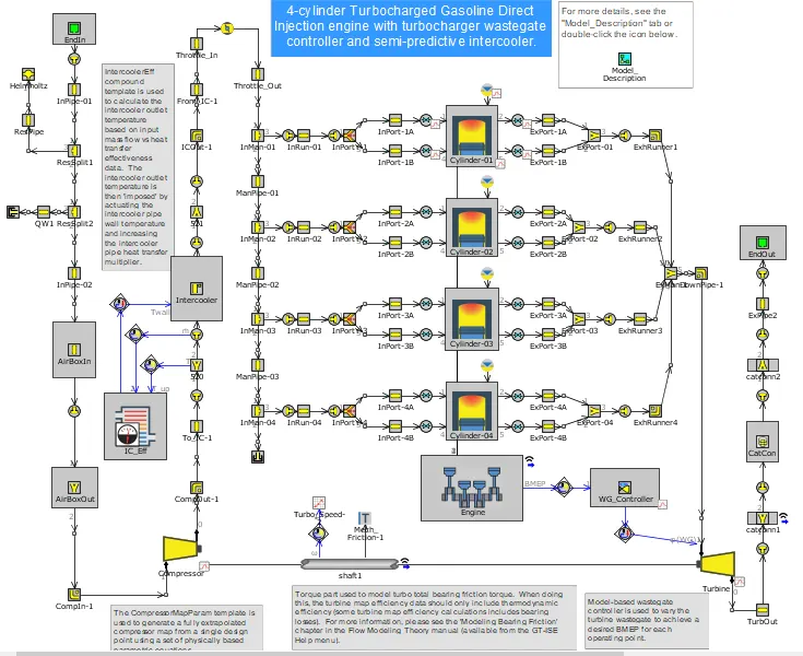
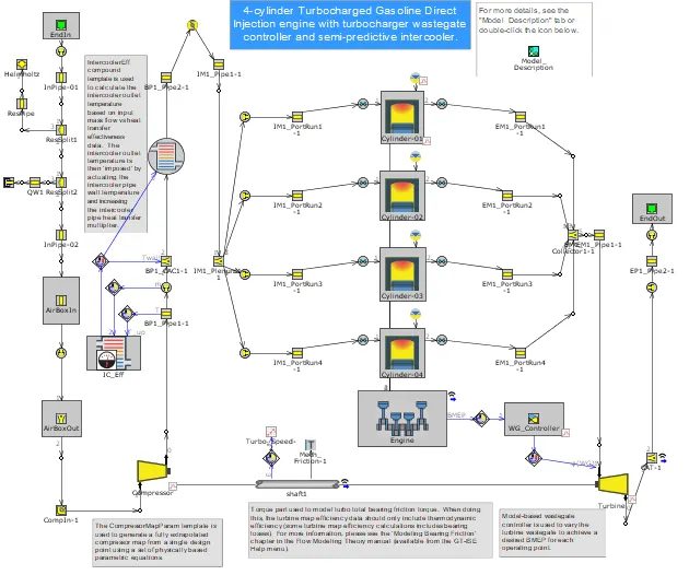
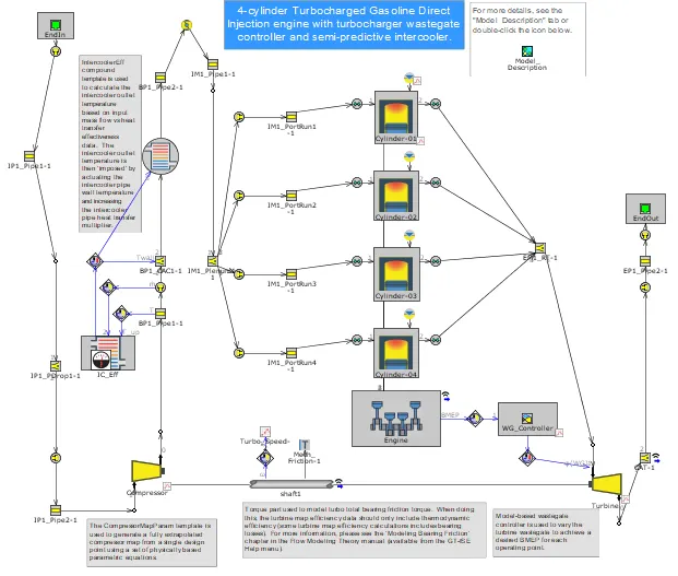
This model is a 4-cylinder 2.0 liter turbocharged Gasoline Direct Injection (GDI) engine. The turbine wastegate is being dynamically controlled in order to target BMEP. A full-load speed sweep is being simulated, from 5000 RPM down to 1000 RPM. A semi-predictive charge air cooler is included such that the outlet temperature is predicted as a function of inlet gas temperature and mass flow rate, coolant temperature, and charge air cooler effectiveness.
This tutorial covers the process of creating a Real-Time capable Fast Running Engine Model from a detailed, high-fidelity engine model. While this tutorial shows a specific set of steps, note that each engine model is unique and so the steps required to convert a detailed model will depend on the complexity of the model, as well as on the goals of the end user. For certain applications, such as Vehicle Thermal Management where engine coolant heat rejection must be maintained, the procedure may differ slightly in order to maintain certain key results. While this FRM process will focus on preserving general engine performance results, special considerations will be noted along the way.
Step 1: Exhaust Manifold
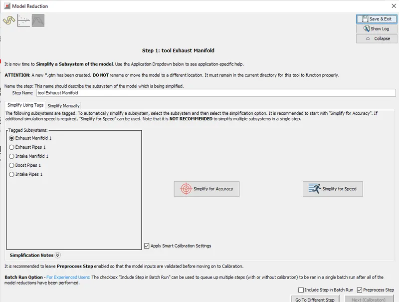
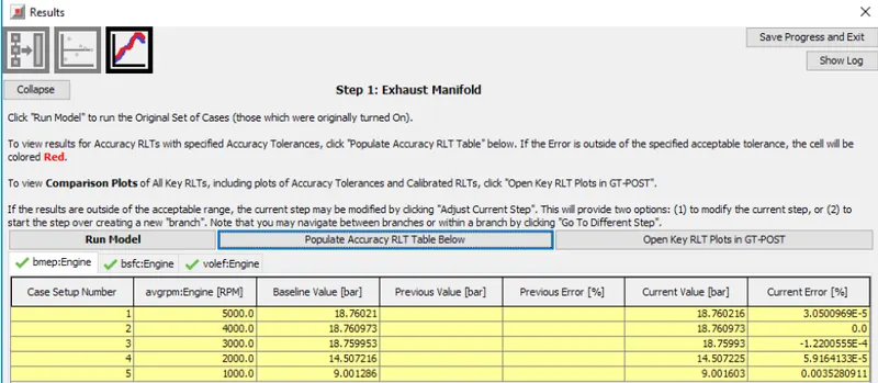
It is most efficient to start by simplifying the subsystem that is currently restricting the time step. For high-fidelity models, this is almost always the exhaust manifold where the highest gas velocities occur, which in turn restricts the time step.
Step 2: Exhaust Pipe
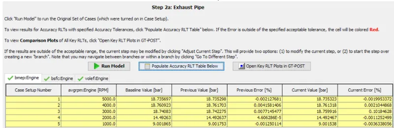
For the second step of model simplification, the exhaust pipes downstream of the turbine will be simplified
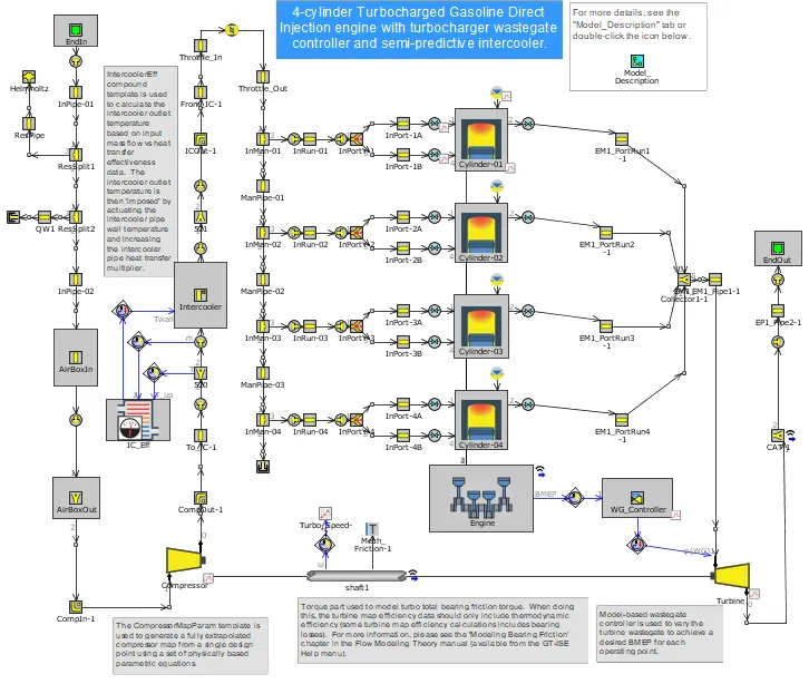
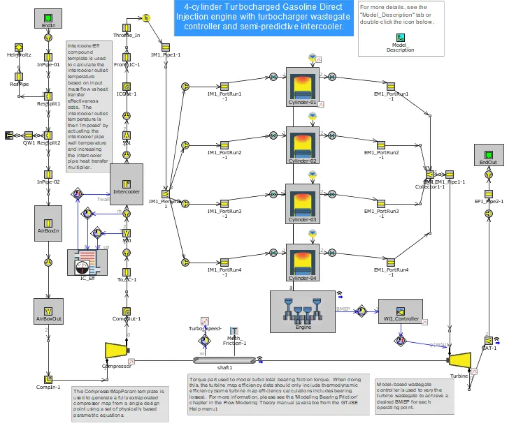
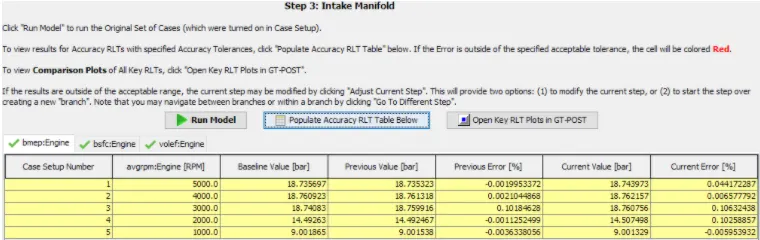
Step 3: Intake Manifold : Caliberation is done with respect to Compressor Massflow Average outlet pressure
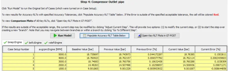
Step 4: Compressor Outlet Pipe
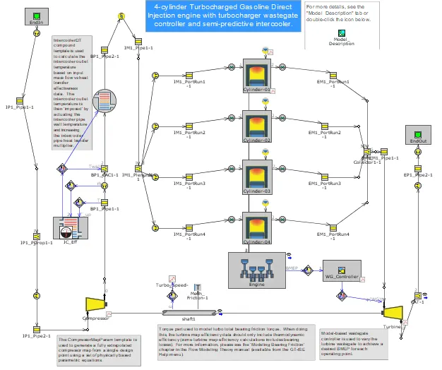
Step 5: Intake Pipes
Step 6: Additonal Changes
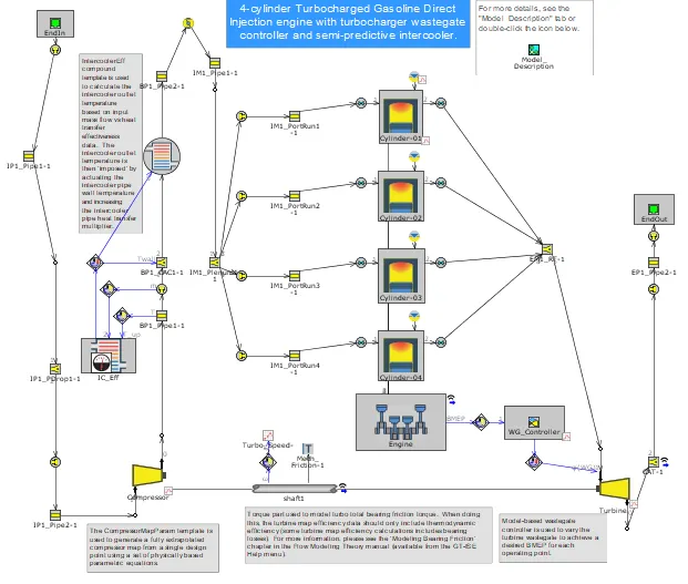
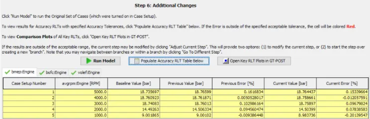
All the exhaust runner volumes are now merged in to Single flow volume to find out the speed of simulation
Step 7: Cylinder Slaving
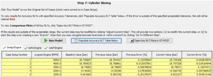
The final simplification to the model will utilize the Cylinder Slaving capability of the EngCylinder component. Cylinder Slaving is the process in which equations and wave dynamics is solved for one master cylinder and other cylinder results are interpreted from the master cylinder instead of solving separately. This process will help in reducing the solution time in case of multi cylinder models. One cylinder is defined as master cylinder and other cylinders are defined as Slave cylinders.
Build FRM Model for following configuration using FRM builder approach
- Bore 102 mm, stroke 115 mm ,CR 17, No of cylinder 6
- CI engine, Twin Scroll Turbine, GT Controller
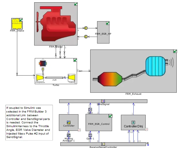
FRM Builder Model
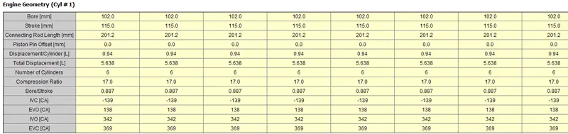
From Case 1-8

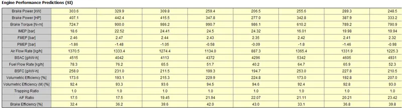
From Case 9-16

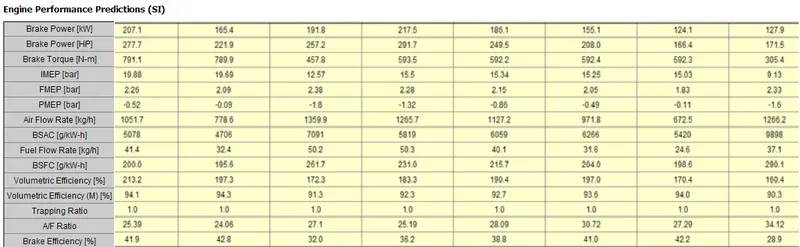
From Case 17-24