Week-7 Challenge: DC Motor Control
AIM:
- To modify a Matlab demo DC model such that armature current doesn’t shoot up when motor changes direction from forward to reverse.
- To compare the Four-Quadrant Chopper DC Drive (DC7) block with H-bridge model.
- To make a suitable EV model using DC7 block and make result report.
THEORY:
FOUR QUADRANT CHOPPER:
A four-quadrant chopper is a chopper which can operated in all the four quadrants. The power can flow either from source to load or load to source in this chopper. In first quadrant, a Class-E chopper acts as a Step-down chopper whereas in second quadrant it behaves as a Step-up chopper. This type of chopper is also known as Class-E or Type-E chopper.
The circuit of a four-quadrant chopper or class-E chopper basically consists of four semiconductor switches CH1 to CH4 and four diodes D1 to D4. The four diodes are connected in anti-parallel. The circuit diagram of this type of chopper is shown below.
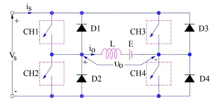
FIGURE.1
BJT H-BRIDGE:
A DC motor spins either backward or forward, depending on how you connect the plus and the minus. If you close switch 1 and 4, you have plus connected to the left side of the motor and minus to the other side. And the motor will start spinning in one direction.
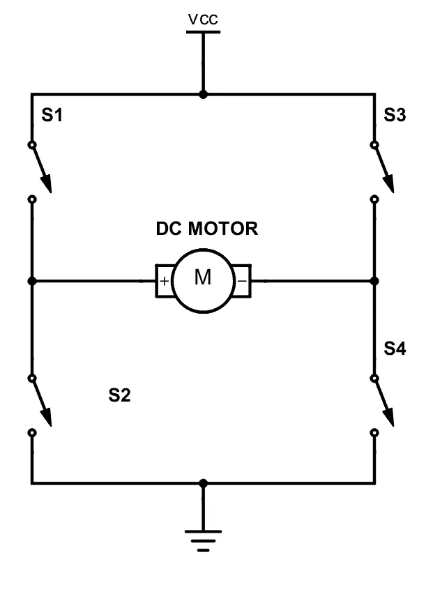
FIGURE.2
OBJECTIVES:
- To modify a Matlab demo ‘Speed control of a DC motor using BJT H-bridge’ model such that armature current doesn’t shoot up when motor changes direction from forward to reverse.
- To compare the Four-Quadrant Chopper DC Drive (DC7) block with H-bridge model.
- To make a suitable EV model using DC7 block and to make result report.
SOLUTION:
TO MODIFY MATLAB DEMO MODEL:
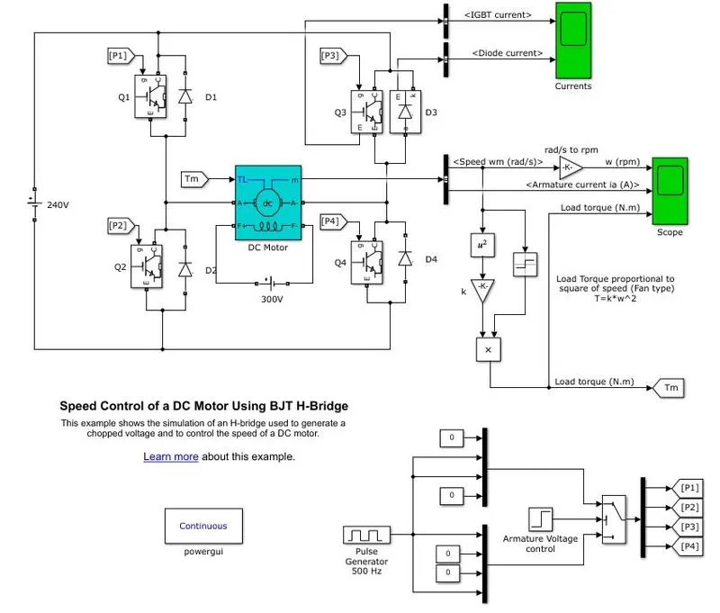
FIGURE.3
- The above model is the default model of a ‘Speed control of a DC motor using BJT H-bridge’. Once this model is run, we get the following results.
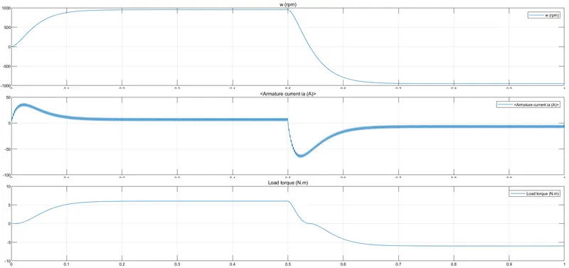
FIGURE.4
- We can observe from above results that, in the second graph which is Armature current graph, there is a jump in the current at the starting of the graph i.e. when speed of motor is increased and then when the speed is constant the current is also constant.
- Now when the speed is decreased at 0.5s time, there is again a jump in the armature current but in the negative direction.
- So, to reduce this jump of armature current we have to make changes in the duty cycle of the vehicle. To change the duty cycle we have to do changes in the ‘Pulse Generator’ Block in the model which is at the bottom. When we click on the ‘Pulse Generator’ block we get the following options.
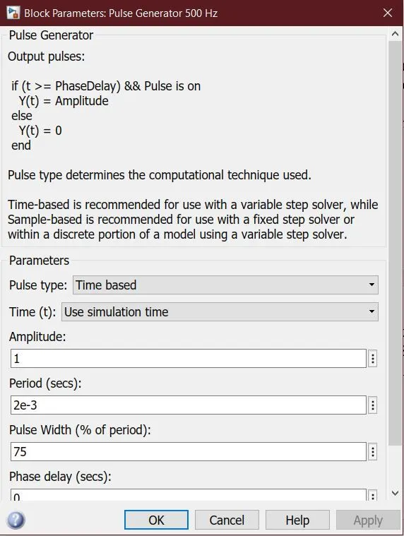
FIGURE.5
- From the above equations we can see there is an option named as ‘pulse width’, which means that for what time the motor is on and for what time motor is off. By default, it is set as 75% which means that for 75% of time the motor is on and rest 25% of time the motor is off.
- Now we have changed this value to reduce the jump in the armature current. To reduce the jump, we have to reduce the value of pulse width.
- After changing the value and running the model we get the following results.
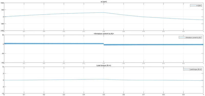
FIGURE.6
- From the above results we can observe, now there is no jump in the armature current since we have reduced the duty cycle to 40%. So, if the duty cycle is less there will be less jump in the current.
- Thus, the jump in the armature can be controlled by changing the duty cycle in pulse generator.
COMPARING FOUR-QUADRANT CHOPPER AND H BRIDGE MODEL:
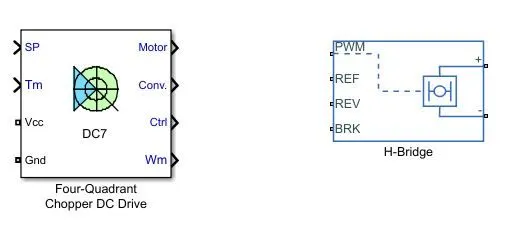
FIGURE.7
- We can observe the difference between both the blocks, where in the ‘Four-Quadrant DC Drive’ we the outputs as the motor measurement vector. This vector is composed of two elements, the DC motor measurement vector (containing the speed, armature current, field current, and electromagnetic torque values). Note that the speed signal is converted from rad/s to rpm before output.
- The IGBT/Diode device measurement vector. This vector includes the converter output voltage. The output current is not included since it is equal to the DC motor armature current. Note that all current and voltage values of the converter can be visualized with the Multimeter block.
- The controller measurement vector. This vector contains, the armature current reference, the duty cycle of the PWM pulses, the speed or torque error (difference between the speed reference ramp and actual speed or between the torque reference and actual torque). The speed reference ramp or torque reference.
- But the H-bridge block represents an H-bridge motor driver. The block has the following two Simulation mode options:
- PWM — The H-Bridge block output is a controlled voltage that depends on the input signal at the PWM port. If the input signal has a value greater than the Enable threshold voltage parameter value, the H-Bridge block output is on and has a value equal to the value of the Output voltage amplitude parameter. If it has a value less than the Enable threshold voltage parameter value, the block maintains the load circuit using one of the following three Freewheeling mode options:
Via one semiconductor switch and one freewheeling diode
Via two freewheeling diodes
Via two semiconductor switches and one freewheeling diode
- The first and third options are sometimes referred to as synchronous operation.
- The signal at the REV port determines the polarity of the output. If the value of the signal at the REV port is less than the value of the Reverse threshold voltage parameter, the output has positive polarity; otherwise, it has negative polarity.
|
Sr No. |
FOUR QUADRANT CHOPPER |
H BRIDGE |
|
1. |
Operates in all four quadrants i.e. Forward Motoring, Forward Braking, Reverse Motoring, Reverse Braking. |
Operates only in two quadrants i.e. Forward Motoring and Reverse Motoring. |
|
2. |
Better control of the vehicle. |
Less control of the vehicle. |
|
3. |
Less damage occurs for the motor and controller. |
Comparatively causes more damage to motor and controller. |
|
4. |
Signals are interrupted to change the direction of the motor. |
Polarity of the current is reversed to change the direction of the motor. |
|
5. |
Signal are not continuous and they are discrete. |
Signals are continuous . |
TO MAKE A SUITABLE EV MODEL USING DC7 BLOCK
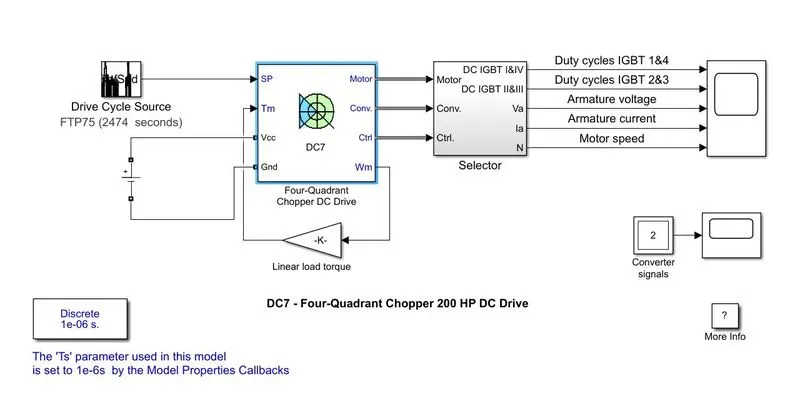
FIGURE.8
- To make an EV model we have changed the AC source to a DC source by using a “’DC Voltage’ Block.
- For the speed reference we used a standardized driving cycle which will be speed reference for the model.
- Then when we run the model, we get the following results.
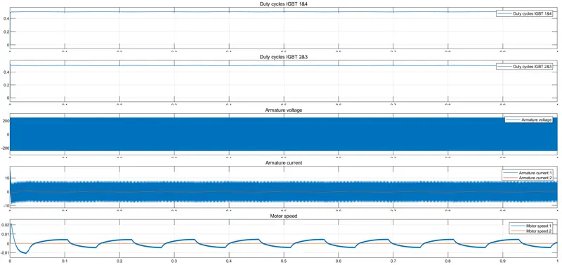
FIGURE.9
- In the results we can find that in first and second graph the duty cycles of IGBT 1&4 and IGBT 2&3 are very smooth as their working frequency is very high, the working of both duty cycles is opposite since they work in combinations. If we observe carefully, we can see that both these graphs are opposite to each other, in the start of the graph we can see the opposite lines in both graphs.
- In the next graph, how the voltage is fluctuating between 200 to -200, since this is voltage used by motor for different speeds and since the working of IGBTs is at high frequency so the changes in voltage is also at high rate, so we can see only a smooth graph in total.
- In the next graph we can observe that the armature current is high initially since vehicle needs more power initially which in turn requires high current, then later on we can observe that the armature current is fluctuating between 10 to -10 according to the working of the IGBTs.
- Next graph shows how the motor speed is changing according to the drive cycle, initial motor speed is more since vehicle has to move. And the it goes at a constant cycle.
CONCLUSIONS:
- Thus, all the objectives are achieved successfully.
- Similar approach can be followed to understand and model similar type of concepts.