Week-7 Challenge: DC Motor Control
1.0
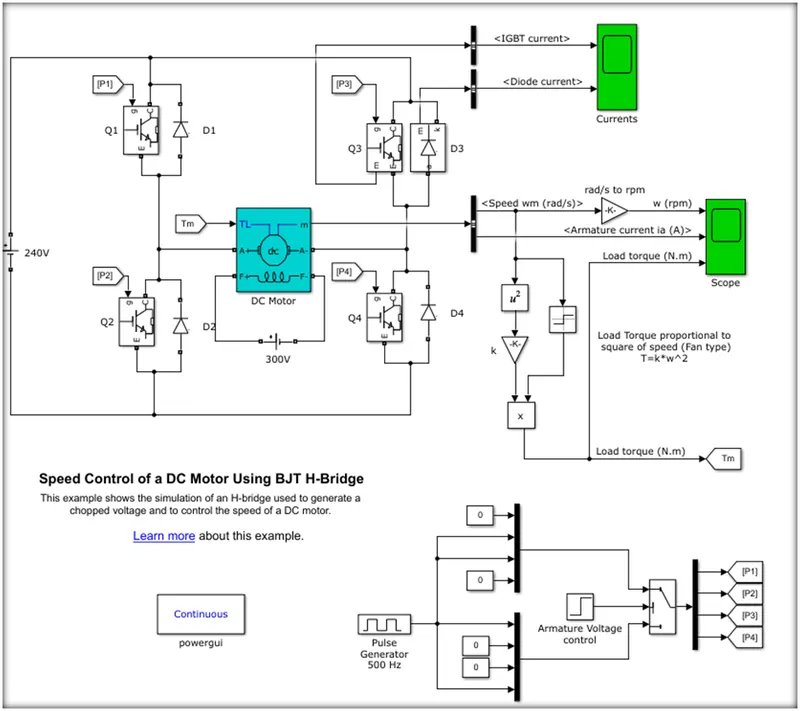
Speed control of a DC motor using BJT H-bridge' demonstrates how to control the speed of a DC motor by adjusting the voltage applied to the motor using a bipolar junction transistor (BJT) H-bridge. The model includes the following key components:
Step input: Represents the desired motor speed reference signal.
PWM Generator: Generates a pulse-width modulated signal to control the H-bridge and, in turn, the motor voltage.
Controlled Voltage Source: Provides a stable DC voltage to the H-bridge.
H-Bridge: Consists of BJT transistors that control the direction and magnitude of the voltage applied to the motor.
DC Motor: Represents the motor with specified parameters such as armature resistance, inductance, and torque constant.
Scope: Displays the motor speed during the simulation.
Use command Power_hbridge in MATLAB to open the predefined circuit.
In general, an H-bridge is a rather simple circuit, containing four switching elements, with the load at the centre, in an H-like configuration:
An H-bridge is an electronic circuit that allows voltage to be applied across a load (typically a DC motor) in either direction. It consists of four switches arranged in an "H" configuration. These switches can be transistors (BJTs, MOSFETs), relays, or other types of electronic switches. The working method of an H-bridge can be described in the following steps:
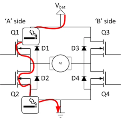
Configuration of switches: In an H-bridge, there are two pairs of complementary switches (high-side and low-side switches). Each pair consists of one switch connected to the positive supply voltage and the other connected to ground (or the negative supply voltage). The switches in each pair must never be turned on simultaneously, as this would create a short circuit.
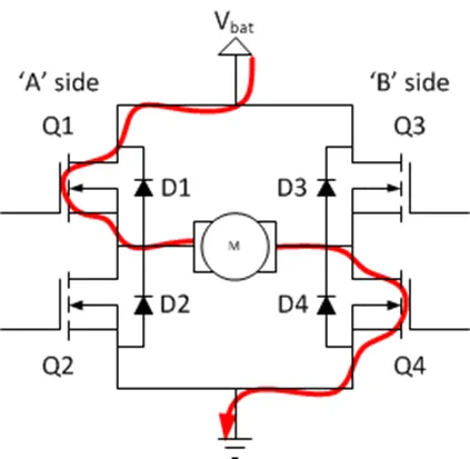
Forward operation: To drive the motor in the forward direction, the high-side switch on one side of the bridge is turned on, and the low-side switch on the opposite side is also turned on. This configuration allows the current to flow from the positive supply voltage, through the motor, and to ground, causing the motor to rotate in the forward direction.
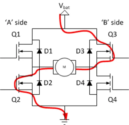
Reverse operation: To drive the motor in the reverse direction, the high-side switch on the side opposite to the forward operation is turned on, and the low-side switch on the other side is also turned on. This configuration allows the current to flow from the positive supply voltage, through the motor in the opposite direction, and to ground, causing the motor to rotate in the reverse direction.
Braking: To apply a braking force to the motor, both high-side switches or both low-side switches can be turned on simultaneously. This configuration creates a short circuit across the motor terminals, causing the motor to decelerate rapidly due to the generated counter-electromotive force (back EMF). This is known as dynamic or regenerative braking.
Coast or freewheel: To allow the motor to coast or freewheel, all switches are turned off. In this configuration, there is no current flow through the motor, and it continues to rotate due to its inertia.
Inputs signals
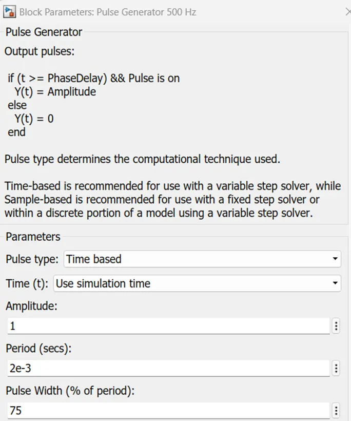
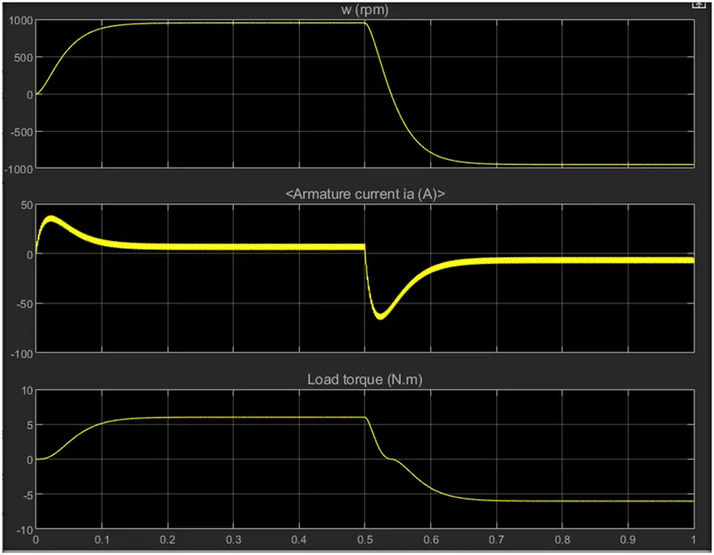
Armature current shoot-up from the scope results
- When you run the simulation and look at the results in the Scope block, you may notice an armature current shoot-up at the start. This is because the motor starts from a stop (zero speed), and the step input causes a quick shift in voltage across the motor terminals. Because the rate of change of current is large at the start, the inductance of the motor causes an initial high current to flow. As the motor speeds up, the back EMF rises and the current falls to a steady-state value.
The Four-Quadrant Chopper DC Drive (DC7) block’. Compare it with the H-bridge model.
- When the Four-Quadrant Chopper DC Drive (DC7) block is compared to the BJT H-bridge model:
- The H-bridge model controls the motor voltage using a BJT-based H-bridge circuit, whereas the Four-Quadrant Chopper DC Drive (DC7) block controls the motor voltage with a four-quadrant chopper circuit.
- The H-bridge model allows for bidirectional motor control (forward and backward), but the Four-Quadrant Chopper DC Drive (DC7) block supports bidirectional control and regenerative braking, allowing for operation in all four quadrants.
- The Four-Quadrant Chopper DC Drive (DC7) block is a more complete model with features such as an internal current control loop, current limiting, and a PI speed controller. Without these extra capabilities, the H-bridge model displays a simpler design for controlling motor speed.
3.0
Brushless DC (BLDC) motors are a type of electric motor that, when compared to brushed DC motors, provide higher efficiency, longer life, and require less maintenance. They are frequently utilised in electric vehicles, consumer electronics, and industrial automation.
The operation of a BLDC motor is summarised in the following points:
- Design: BLDC motors are made up of a stator with many windings grouped around its circumference and a rotor with permanent magnets. The stator remains stationary and generates the magnetic field, whilst the rotor moves and is propelled by the interplay of the magnetic fields.
- Most BLDC motors use a three-phase stator winding design, with the rotor position monitored every 60 electrical degrees. The stator currents are set such that two of the three windings are energised at any given moment, providing a revolving magnetic field that powers the rotor.
- Torque is generated by the interaction of the magnetic field produced by the stator windings and the permanent magnets on the rotor, which causes the rotor to rotate. The torque is proportional to the product of stator current and magnetic field generated by rotor magnets.
- Controlling the speed of a BLDC motor is done by altering the voltage or current provided to the stator windings. This can be accomplished through the use of techniques such as pulse width modulation (PWM), which alters the voltage or current by varying the duty cycle of the applied waveform.
Efficiency: Because brushes and commutators cause friction and energy waste, BLDC motors are more efficient than brushed DC motors. The lack of brushes also results in less maintenance and a longer motor life.
BLDC motors are low-maintenance, efficient, and dependable motors that use electronic commutation to control the current in the stator windings, producing torque through the interaction of the magnetic fields formed by the stator and rotor. They have substantial advantages over brushed DC motors and are utilised in a wide range of applications.