Week-7 Challenge: DC Motor Control
1/A.
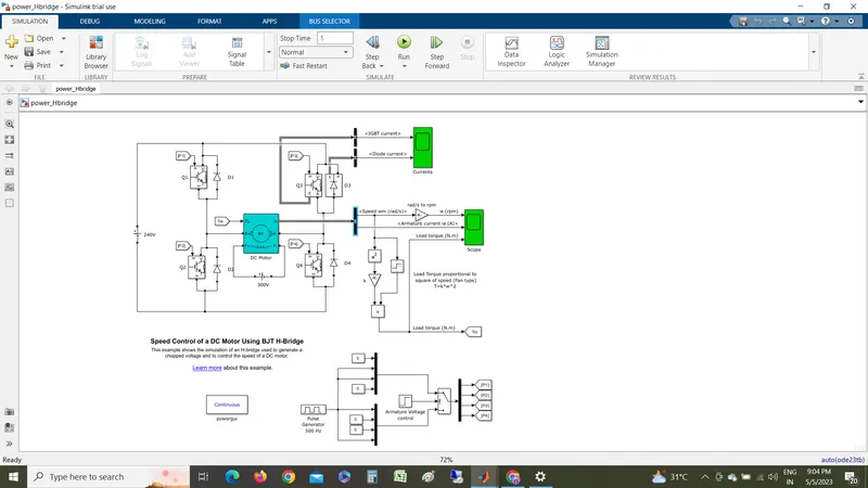
DESIGN
As talking about the design on DC motor simulink,the DC motor field winding is connected to 300v source while the armature connected to 4 BJT H-bridge to controll the motor. In every BJT,a diode in connected in paralla because no back current flow. It work like safty for the BJT . Q1,Q2,Q3,Q4 are 4 BJT connected to armature winding . A scope is connected to show the BJT or IGBT current and diode current.Another scope is taken for view of armature current , speed and torque of motor. A mathmatical expression has been developed to generate the TORQUE. Regarding to $ BJT P1,P2,P3,P4 used for triggering signals to BJT through the pulse generator.
WORKING
for the forward mode and forward braking we used to switch the Q1 & Q4 and for reverse , reverse braking Q2 &Q3 is used for it. switching more thanany of the combination will be generate malfunction to circuits as well as to the motor in real time .when switching started for forward the current flow from Q1 to Q4 and for reverse direction the current will flow from Q2 to Q3 . the Free wheel diode is used for the braling of both forward and reverse .For forward and reverse selection are done in the Continues block . There is also you can see the selection of BJT for forward and reverse.Although there is 0.5 sec of time interval for switching the conditions.
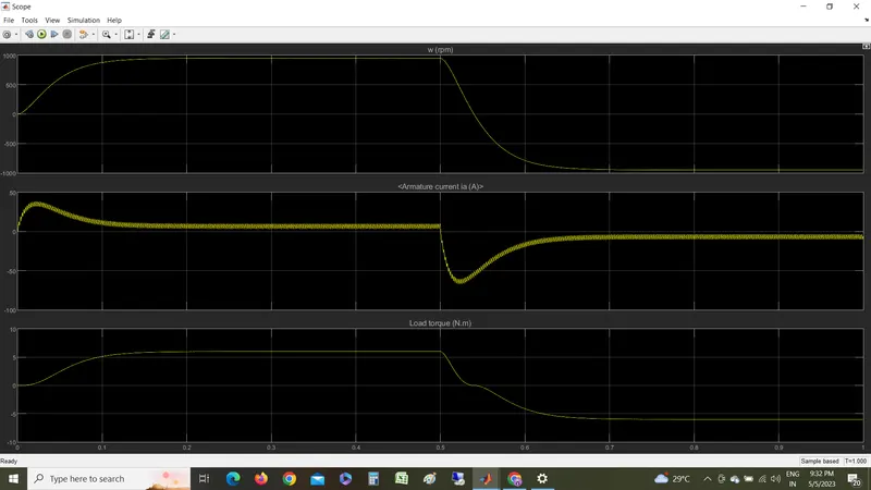
Here observing the out comes of Armature current,speed and torque . all of 3 parameters goes up for the forward in 0.5 sec achiving approximatley 900 rpm where armature curent increse relative and after it goes negative in the the fame of reverse drive as well as the torque is also.
B.
As refering to the above graph the armatrue intially current shoot up is due to sudden increase in voltage which is generated by the duty cycle. like at fullefficiency. If there were changes in voltage by armature controll method , controlling the voltage of armeture leads to run the motor in speed reletively to the chages in voltages.
C.
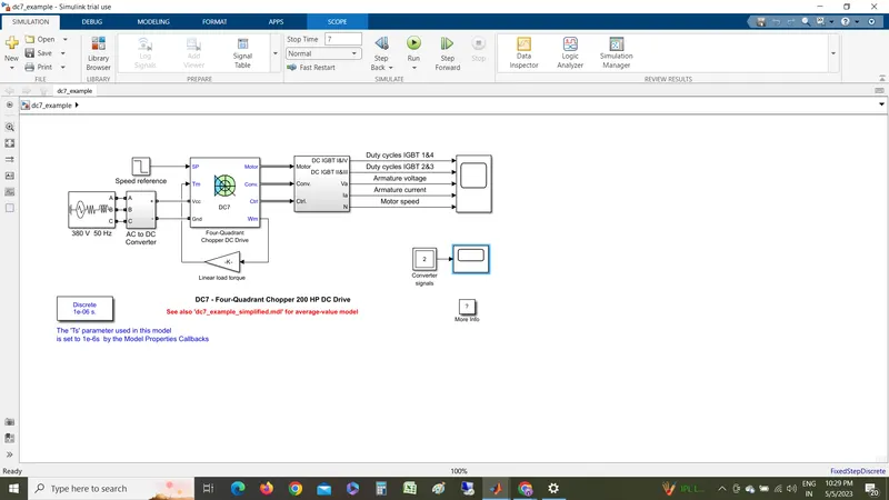
4 Quadrant DC chopper have the inputs of armature voltage,speed reference,motor torque and giving output as motor angular speed, controller etc.
In this 4 IGBT switches are used. pulse givenby PI current controlleer that control current by compairing armature current measured and cycle refreence.for forward regenerstive braking mode Q1,Q4 are on and Q2,Q3 are on for reverse regenertive braking.
mode of operation discete where H-bridge model is contineous .
dynamic braking occures when there is change in polarity while regenerative braking occurs in H-bridge.
IN DC7 current is controlled by PI current contriller and H-bridge can be vary with varying in duty cycle.
smotthing inductor is used in DC7 chopper to controll the current smoothly.
2.
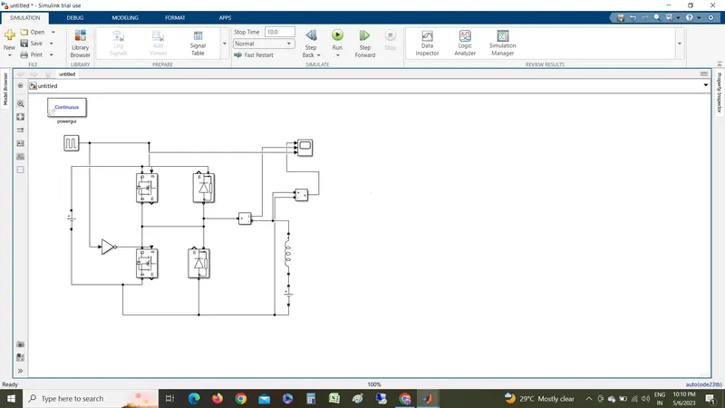
When chopper CH2 is on, or freewheeling diode FDconducts, output voltage v0=0and in case chopper CH1is on or diode D2conducts, output voltage v0=Vs. The load current i0can, however, reverse its direction. Current i0 flows in the arrow direction marked i.e. load current is positive when CH1 is on orFDconducts. Load current is negative if CH2 is on or D2 conducts. In other words, CH1 and FD operate together as type-A chopper in first quadrant. Likewise, CH2 and D2 operate together as type-B chopper in second quadrant.
Average load voltage is always positive but average load current may be positive of negative as explained above. Therefore, power flow may be from source to load or from load to source. Choppers CH1 and CH2 should not be on simultaneously as this would lead to a direct short circuit on the supply lines. This,type of chopper configuration is used for motoring and regenerative braking of dc motors. The operating region of this type of chopper is shown by hatched area in first and second quadrants
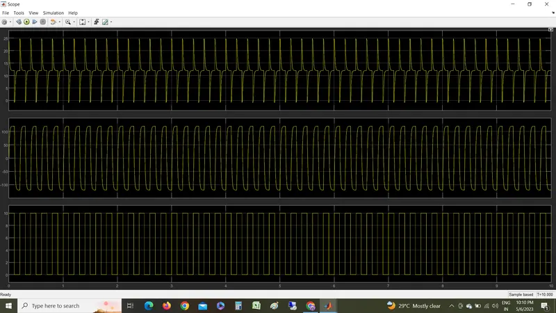
As my graph is not clumsy because of not getting the exact setting for the it. But clearly we can observe that the pulse of square wave having maximum amplitude of 10v as i set it. andcurrent moving with positive to nagative polatity as inductor storing the charge and emitting the charge when the power is cutt-off.
3.
BLDC MOTOR
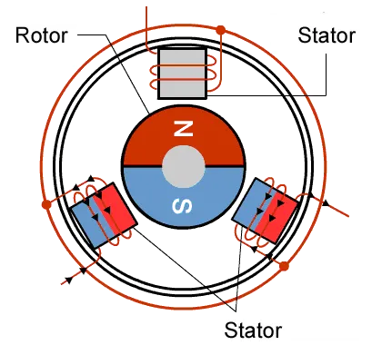
As it name brushless there no brush used to power where the brush motor delivers current when through current into coils on rotor. But here the rotor is made of parment magnets, the coil do not rotate but are insteas fixed in place on stator. with the brushed motor , rotation is achives by controlling the magnetic fields generate by the coils on the rotor,while the magnetic fied generated by stationary magnets remains fixed. To change the rotation speed you change the voltage for the coils.With the BLDC motor , it is permanent magnet that rotates; rotation is acived by changing the direction of magnetic field generated by surrounding stationary coils. To control the rotation, you adjust the magintude and direction of current into these coils,since the the rotor is made up with te permanent magnets it needs no current, eliminating the need for brushed and commutatator. current to the fixed coils is ciontrolled from the outside.
advantages
- comtrolling of motor at maximum rotational force.
- it canbe controlled by feed back mechanisim like servo motors
- high durability
- less noise produce
- as no brushes are present so no sparks.