Week-7 Challenge: DC Motor Control
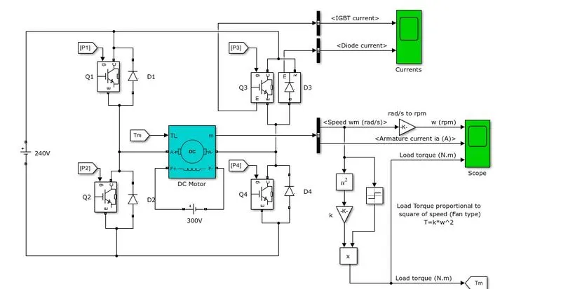
1. Speed control of a DC Motor using BJT H - bridge.
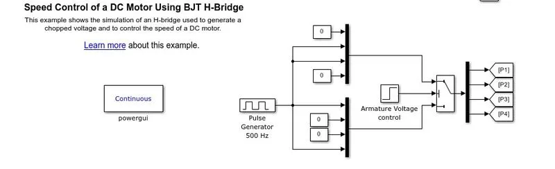
This example shows the simulation of an H-bridge used to generate a chopped voltage and to control the speed of a DC motor.
Description:
- The Bipolar Junction Transistor (BJT) when used for power-switching applications, operates as an IGBT.
- When conducting (BJT operating in the saturated region), a forward voltage Vf is developed between the collector and emitter (in the range of 1 V). Therefore, the IGBT block can be used to model the BJT device.
- The IGBT block does not simulate the gate current controlling the BJT or IGBT.
- The switch is controlled by a Simulink® signal (1/0)
- The DC motor uses the preset model (5 HP 24V 1750 rpm). It simulates a fan type load (where Load torque is proportional to the square of speed)
- The armature mean voltage can be varied from 0 to 240 V when the duty cycle (specified in the Pulse Generator block) is varied from 0 to 100%
- he H-bridge consists of four BJT/Diode pairs (BJT simulated by IGBT models). Two transistors are switched simultaneously: Q1 and Q4 or Q2 and Q3.
- When Q1 and Q4 are fired, a positive voltage is applied to the motor and diodes D2-D3 operate as free-wheeling diodes when Q1 and Q4 are switched off.
- When Q2 and Q3 are fired, a negative voltage is applied to the motor and diodes D1-D4 operate as free-wheeling diodes when Q2 and Q3 are switched off.
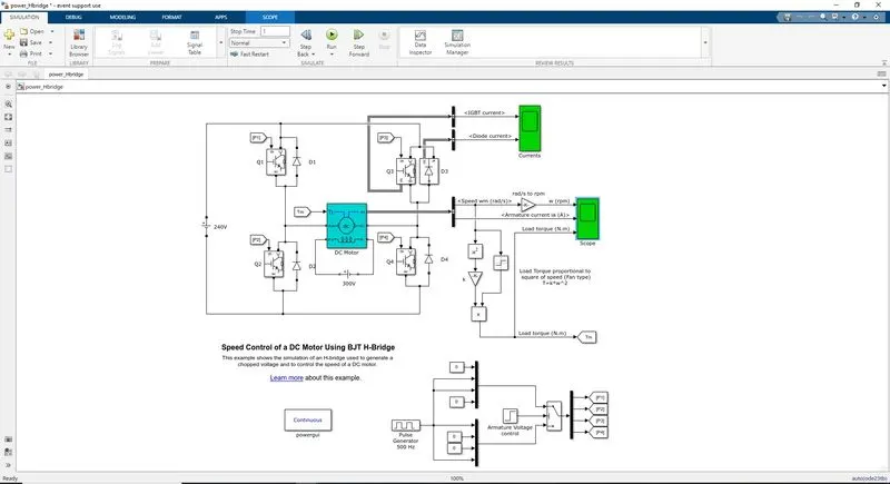
Result: for 75% duty cycle
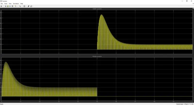
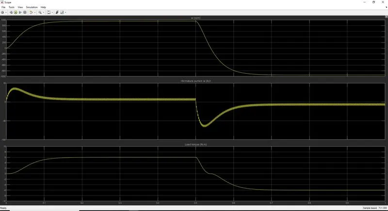
B) Armature current shoot up
the initial current shoot up is due to a sudden increase in voltage which inurns regulated by the duty cycle. In this case, motor is driven in 75% of the duty cycle. (i.e) 0.75*240= 180 V.
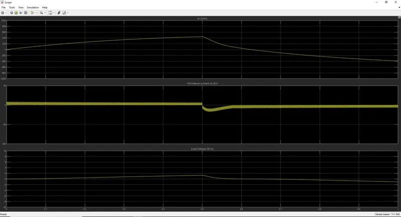
We can change the duty cycle to 50%(120 V) and seen the results as
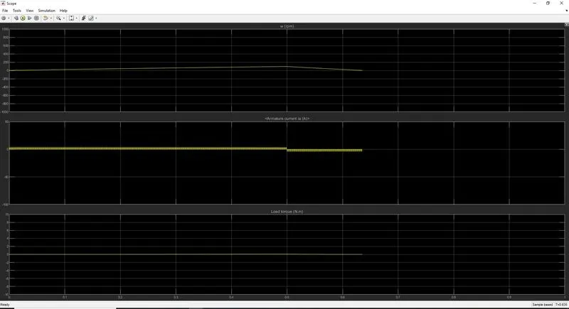
for 25% duty cycle
C) The four-quadrant chopper DC Drive (DC7) Block.
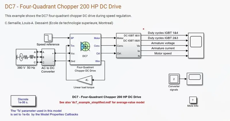
working:-
- Four Igbt switches are used.
- pulses are given from PI current controller, which controls the pulses by comparing armature current measurement and current reference.
- Current reference can be generated by using a regulation switch in that torque reference and PI speed controller pulses, that internally compared by the speed of the motor and reference speed given as input.
- Forward motoring mode, forward regenerative breaking mode: Q1,Q4 are on and Q2,Q3 are in off.
- Reverse motoring mode, reverse regenerative breaking mode: Q2,Q3 are on and Q1,Q4 are in off.
Comparison with H-bridge
- In DC7 chopper model speed is controlled by varying current pulses from PI current controller and in H-brige model speed is controlled by varying duty cycle voltages.
- In DC7 regenerative braking is occurring whereas in H bridge model dynamic breaking occurs when the polarities of the current flow are changed.
- In the four-quadrant DC chopper model smoothing inductance is used for smooth increase and decrease in current flow which in turn controls the motor speed smoothly, while in H-bridge it is not present.
- Here the operation is discreet and in H-bridge model it is continuous.
- Hence 4 quadrant DC choppers are used mostly in electric vehicles.
3. BLDC motor
- BLDC motor is a brushless DC motor which is also known as synchronous motor.
- It has higher efficiency compared to other motors.
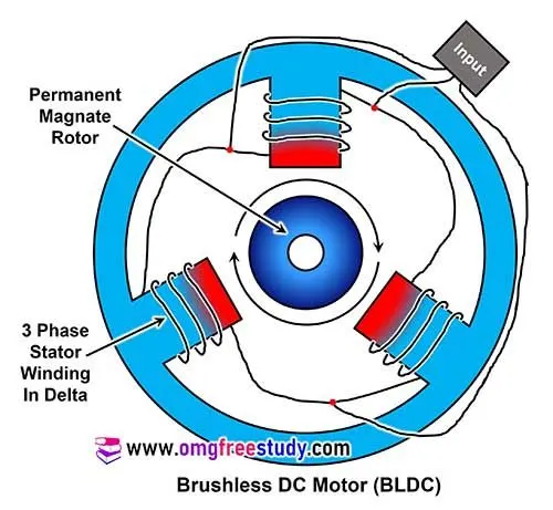
- The construction of BLDC motor is similar to that of a permanent magnet synchronous motor.
- Inverter has to replace the mechanical inverter called as commutator of a DC motor.
- BLDC motor can be derived from a mechanically commutated DC motor with three armature slots. In armature winding connection of three phase winding is connected in delta.
- The commutator acts like a 3- phase frequency converter. Stator (excitation) and rotor (armature) change places.
- In BLDC motor commutation depends on the position of the rotor.
- The angle between the MMF (magneto-motive forces) of the stator and rotor is fixed at 90 degrees electrical.
- So the motor produces maximum torque and needs low reactive current it might be useful to advance commutation by few degrees to compensate the effects of the stray inductance and minimize reactive current.
- Speed can only be controlled by the motor voltage.
- The motor behaves like a DC motor but in synchronous motor, there are no problems with stability at any speed.
- Because of the PWM frequency inverter, variation of the motor voltage can be achieved easily by changing the duty cycle of the pulse width modulation. Suitable PWM techniques allow regenerative breaking, which increases dynamic and efficiency of the drive.
- Using best PWM techniques BLDC can operate smoothly with noiseless operation.
Advantages:-
- No mechanical commutator or brushes. Hence low maintenance and long life.
- Noiseless operation due to the absence of brush.
- Can run at much higher speeds.
- Higher efficiency.
- Electronic control of speed and torque is possible.
2. 2 Quadrant chopper.
The below figure shows the two quadrant operation of the chopper.
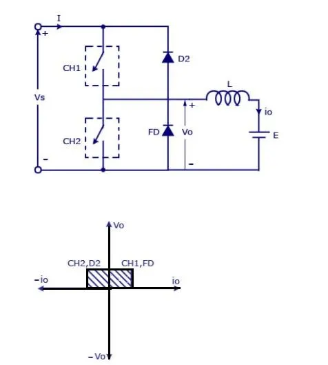
Where,
Vs=DC voltage source.
CH1= Power electronic switch 1.
CH2= Power electronic switch 2.
D2,FD = Free wheeling diodes.
L=Inductor load.
E Back emf from load.
In this type of Chopper, the average voltage will be always positive but the average load current might be positive or negative. The two Switches CH1 and CH2 should not be turned on simultaneously as the combined action may cause a short circuit in supply lines. For regenerative braking and motoring, this type of chopper configuration is used.
We will always get a positive output voltage V0 as the freewheeling diode FD is present across the load. When the chopper CH1 is on the current flows from source to load. The inductor stores energy. When Ch1 turns OFF the freewheeling diode starts conducting and the output voltage v0 will be equal to Vs. The direction of the load current i0 will be reversed. The current i0 will be flowing towards the source. The load current will be negative when the CH2 is on. The current completes its path through diode D2.
Mode of operation:
- Here either one should be ON at a time, either CH1 or CH2.
- If CH1 is ON the current flows from source +ve to load(here DC motor), passes through L and E to -ve terminal of the source.(1st quadrant)
- If CH1 is OFF the, FD diode conducts and completes the circuit (L-E-FD-L) as stored energy in inductor L. The voltage across is also positive voltage, and the current direction also positive.
- Now If CH2 is ON, the Current flow from E(Load current) completes the circuit(L-CH2-E).
- If CH2 gets OFF, the current passes through D2 towards the source and completes the circuit(E-L-D2-+ve source- -ve source-E).
- In this stage, regenerative breaking occurs. (2nd quadrant).
- This cycle continues again up to stop time.