DC Motor Control using Power Electronics
DC MOTOR CONTROL :-
AIM :-
To analyze the speed control of DC motor using BJT-H bridge, Chopper and EV model using DC 7 block.
PLATFORM USED :-
- Software – Matlab R2020a
SYSTEM SPECIFICATIONS :-
- Manufacturer - DELL
- Model – Vostro 3478
- Operating System - Windows 10
- Processor - Intel(R) Core(TM) i5-8250U CPU @ 1.60GHz 1.80GHz
- RAM – 8 GB
OBJECTIVE :-
- To analyze the speed control of DC motor using BJT-H bridge and to suppress the armature current during phase transition.
- Compare the speed control scenario with BJT-H bridge using DC 7 block.
- Make a suitable EV model using DC7 block and make result report.
QUESTION & ANSWER :-
1) Run MATLAB demo ‘Speed control of a DC motor using BJT H-bridge’. Modify the model such that armature current doesn’t shoot up when motor changes direction from forward to reverse.
TRANSISTOR :-
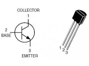
A transistor is a semiconductor device used to amplify or switch electronic signals and electrical power. BJT stands for Bipolar Junction Transistor.
H – BRIDGE CIRCUIT :-
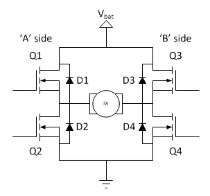
H – Bridge is an electronic circuit where it’s used to control the DC motor drive (forward and reverse motion) according to the voltage applied by using switching application. Where Q1, Q2, Q3 & Q4 are the switches and D1, D2, D3 & D4 are the diodes connected respectively.
FORWARD MOTORING :-
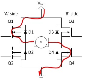
Consider the case where Q1 and Q4 are turned on, the left lead of the motor will be connected to the power supply, while the right lead is connected to ground. Then current starts flowing through the motor which energizes the motor in the forward direction and the motor shaft starts spinning.
REVERSE MOTORING :-
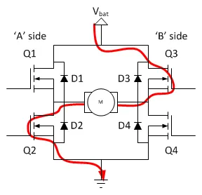
Consider the case where Q2 and Q3 are turned on, the left lead of the motor will be connected to the power supply, while the right lead is connected to ground. Then current starts flowing through the motor which energizes the motor in the reverse direction and the motor shaft starts spinning accordingly.
SIMULATION IN SIMULINK :-
SIMULATION I :-
- DC Motor is of 5 HP 24 V 1750 RPM.
- The armature mean voltage can be varied from 0 to 240 V when the duty cycle (specified in the Pulse Generator block) is varied from 0 to 100%.
- The motor starts in the positive direction with a duty cycle of 75% (mean DC voltage of 180V) at t= 0.5 sec.
MODEL :-
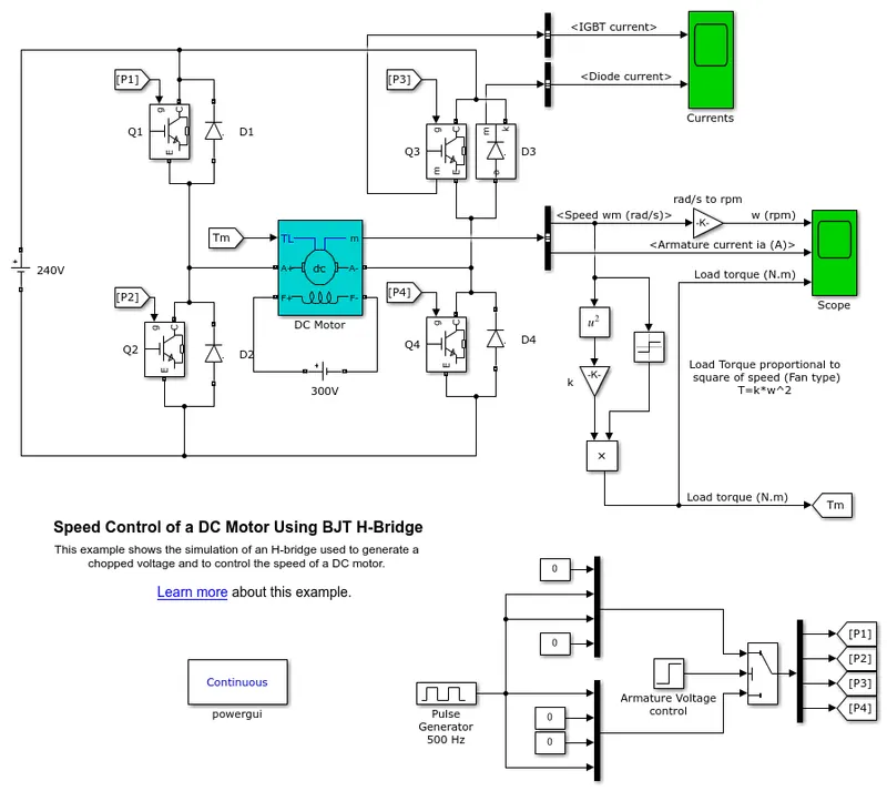
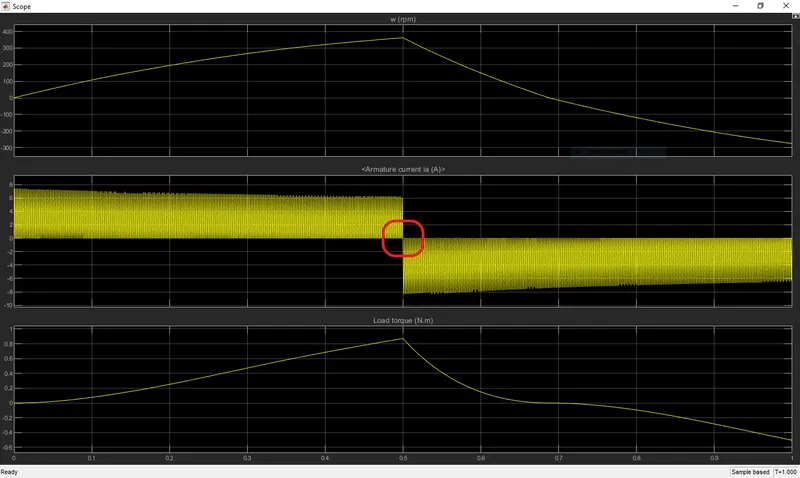
Initially the model is simulated with duty cycle of 75 % for 1 sec and the output results are obtained. While transition from forward motoring to reverse motoring there is a high fluctuation in the armature current (`I_a`) then it’s stable, so we are going to supress the issue and substantiate with a solution.
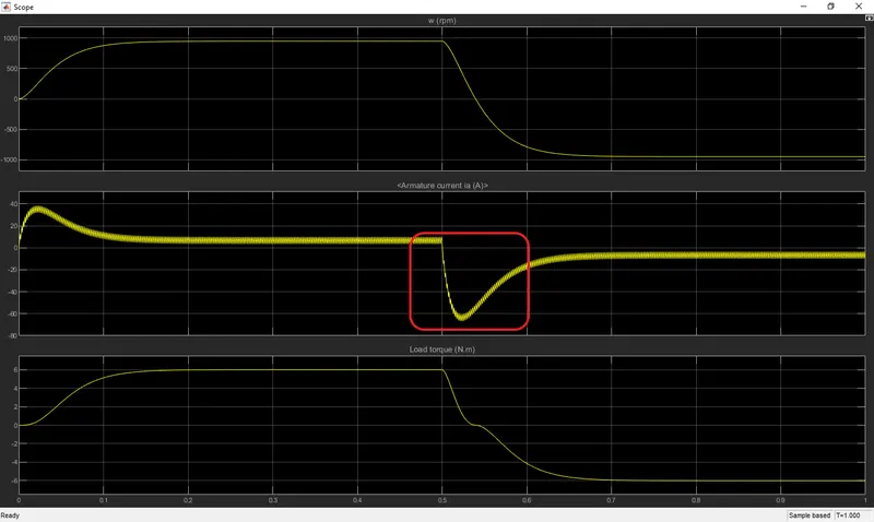
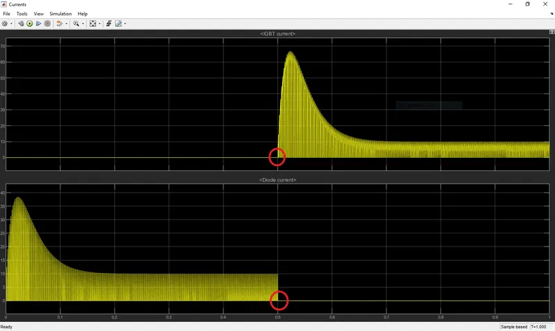
Here we can see that the armature current (`I_a`) is hitting a value of - 67 Amps during the transition state from forward to reverse at 0.5 sec. If this scenario exists for a long period of time it will lead to failure of the components. We can verify that the transition (forward to reverse) is achieved smoothly by the DC motor at 0.5 sec by viewing the plot.
SIMULATION II :-
- The motor starts in the positive direction with a duty cycle of 44 % at t = 0.5 sec.
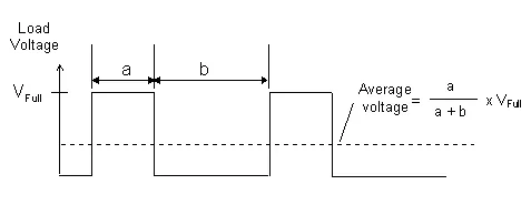
- Mean DC Voltage = Duty Cycle * Full Voltage = 0.44*240 = 105.6 V
OUPUT :-
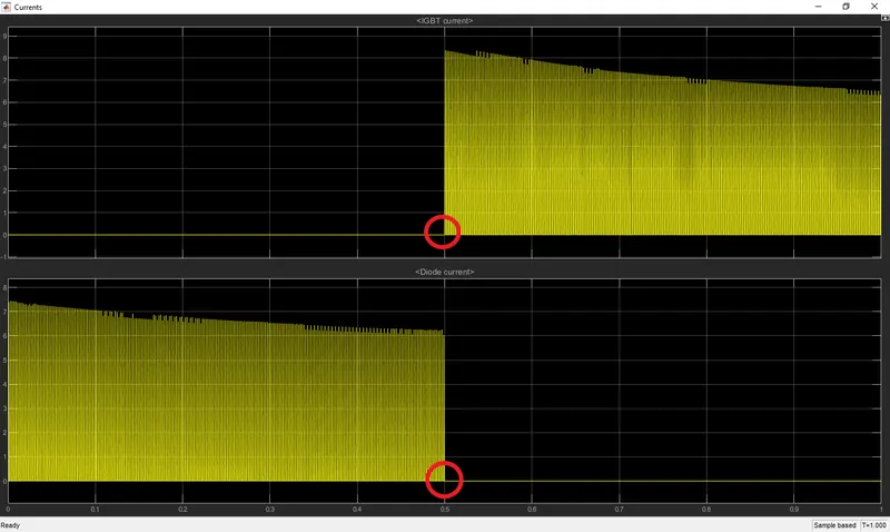
Here we can observe that there is no fluctuation in the armature current (`I_a`) and the maximum value is around – 8.2 Amps at 0.5 sec after transition.
And also the transition (forward to reverse) is achieved smoothly by the DC motor at 0.5 sec by viewing the plot.
CONCLUSION :-
We can conclude that the above situations are related to OHM’s law, where the reduction in voltage the armature current also reduces.
`OHM’s LAW : Vα I`

From the above relation we can say that the motor armature current can be controlled through the voltage supply.
2) Refer to help section of ‘The Four-Quadrant Chopper DC Drive (DC7) block’. Compare it with H-bridge model.
FOUR QUADRANT CHOPPER DC DRIVE :-
QUADRANT OPERATION :-
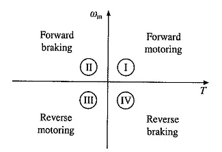
There are four different types of operation in the four quadrants,
- Forward Motoring
- Forward Braking
- Reverse Motoring
- Reverse Braking
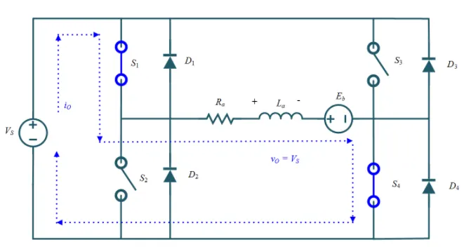
FORWARD MOTORING :-
CASE I :-
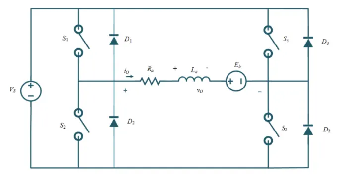
- The switches S1 & S4 are turned ON so it conducts the voltage where output voltage (`v_0`) and output current are positive (`i_o`).
- Eventually the power is positive and the inductor (`L_w`) stores some energy.
- The power flows from source to the load (motor) hence the motor rotates in the forward direction.
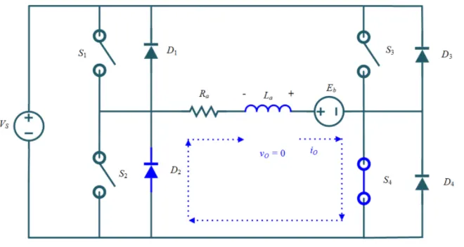
CASE II :-
- The switch S1 will be turned OFF so the energy from the inductor will start flowing.
- The energy will flow through switch S4 and diode D2 until there is energy in the inductor.
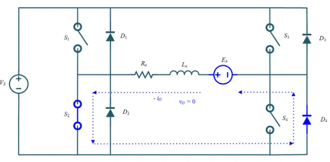
FORWARD BRAKING :-
CASE I :-
- The motor is running in forward direction.
- The switch S2 is turned ON and the current direction reverses which flows through diode D4.
- The output voltage is zero and the Back EMF is resposible for negative current.
- Where the motor starts behaving like generator and the inductor stores the energy.
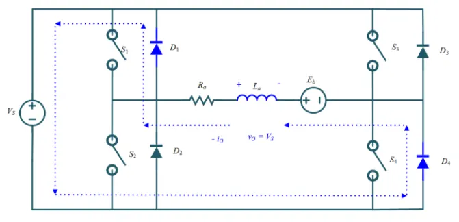
CASE II :-
- All the switches are turned OFF and the current start discharging from the inductor.
- The current flows through diodes D4 & D1 to the source.
- The output current is negative (reverse direction) and the output voltage is positive.
- Where the energy flows from load (inductor) to the source, it’s known as regenerative braking.
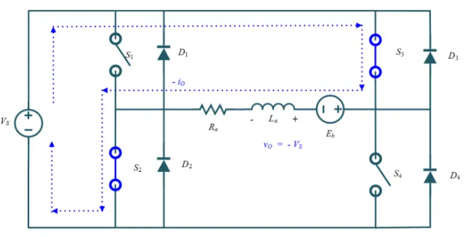
REVERSE MOTORING :-
CASE I :-
- The switch S3 and S2 are turned ON so the power flows from source to load then the inductor stores the energy.
- Both output voltage and ouput current is negative.
- The motors rotates in reverse direction so it’s known as reverse motoring.
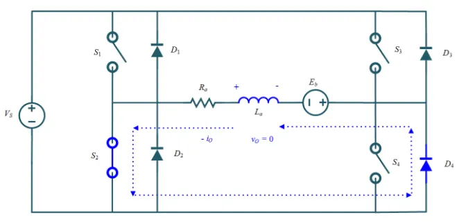
CASE II :-
- The switch S3 will be turned OFF so the energy from inductor will start discharging.
- The energy will flow through switch S2 and diode D4 in negative direction.
- The output voltage is zero and output current is negative.
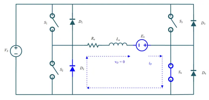
REVERSE BRAKING :-
CASE I :-
- The motor is rotating in reverse direction.
- The switch S4 is turned ON and the current direction reverses which flows through diode D2.
- The output voltage is zero and the Back EMF is resposible for negative current .
- Where the motor starts behaving like generator and the inductor stores the energy.
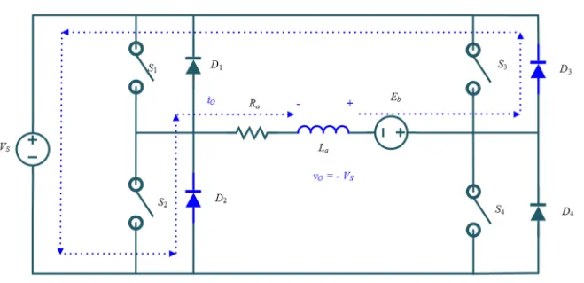
CASE II :-
- All the switches are turned OFF and the current start discharging from the inductor.
- The current flows through diodes D2 & D3 to the source.
- The output current is negative (reverse direction) and the output voltage is positive.
- Where the energy flows from load (inductor) to the source, it’s known as regenerative braking.
MODEL :-
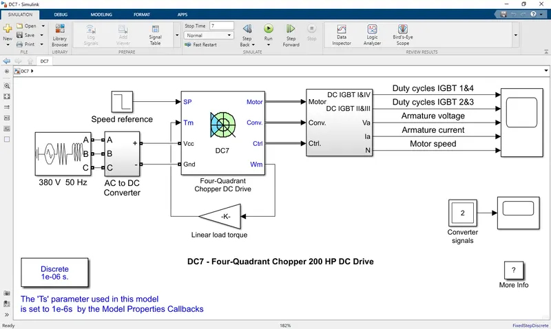
DESCRIPTION :-
- The 200 HP DC motor is separately excited with a constant 150 V DC field voltage source.
- The armature voltage is provided by an IGBT converter controlled by two PI regulators.
- The converter is fed by a 515 V DC bus obtained by rectification of a 380 V AC 50 Hz voltage source.
- In order to limit the DC bus voltage during dynamic braking mode, a braking chopper has been added between the diode rectifier and the DC7 block.
- The first regulator is a speed regulator, followed by a current regulator. The speed regulator outputs the armature current reference (in p.u.) used by the current controller in order to obtain the electromagnetic torque needed to reach the desired speed.
- The speed reference change rate follows acceleration and deceleration ramps in order to avoid sudden reference changes that could cause armature over-current and destabilize the system.
- The current regulator controls the armature current by computing the appropriate duty ratios of the 5 kHz pulses of the four IGBT devices (Pulse Width Modulation).
- The instantaneous pulse values of IGBT devices 1 and 4 are opposite to those of IGBT devices 2 and 3.
- This generates the average armature voltage needed to obtain the desired armature current. In order to limit the amplitude of the current oscillations, a smoothing inductance is placed in series with the armature circuit.
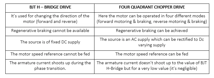
BJT H-BRIDGE vs FOUR QUADRANT CHOPPER DRIVES :-
3) Make a suitable EV model using DC7 block and make result report.
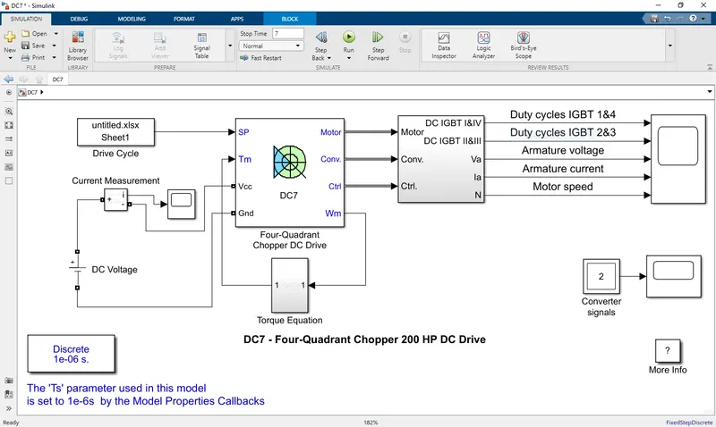
The model has been modified from DC7 block where the following characteristics were added,
- New driving cycle of a vehicle
- Fixed DC source voltage of 100 V
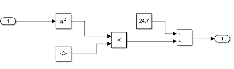
- Torque equation of the motor as `T = 24.7 + 0.0057*ω^2`
DRIVING CYCLE :-
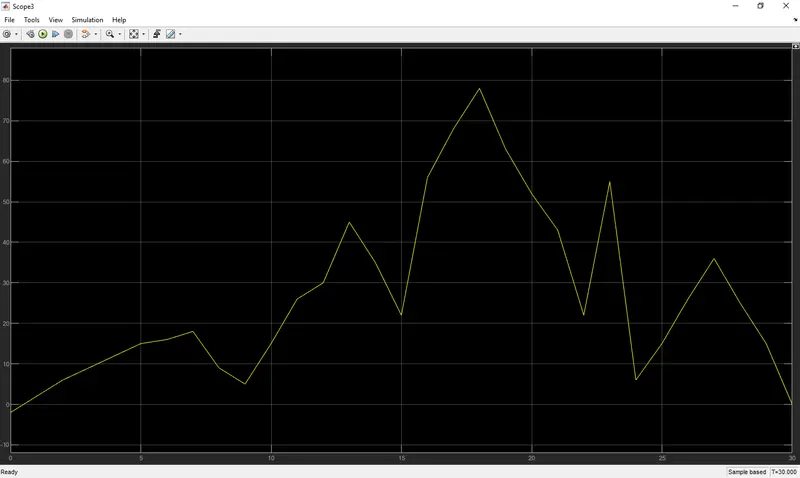
The maximum velocity the vehicle is reaching is around 77 m/s at 17 sec.
TORQUE CHARACTERISTICS :-
The torque equation used in the model is `T = 24.7 + 0.0057*ω^2`
OUTPUT :-
After simulation we could observe that the motor speed () matches with the velocity (m/s) of the driving cycle.
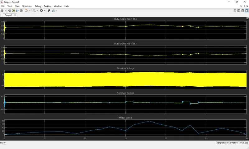
The duty cycles of the IGBT I, II, III & IV are plotted so we can observe that motor has been operated in all four quadrants.
ATTACHMENTS :-