Week-7 Challenge: DC Motor Control
1.A. Speed control of a DC motor using BJT H-bridge
- Here H-bridge DC chopper circuit is designed to control the speed of the motor.
- IGBT acts as BJT in power switching devices.
- Four IGBT switches are used for inverting the DC voltage 0 to 240 v supply.The current flows from collector(C) to emitter(E).
- The gate are controlled by the pulses(0 and 1) according to the armature voltge of motor given by pulse generator.
- This image shoes the voltage value given from initial to final during the step time.According to the pulses on and off the voltage supplied to the IGBT's.
- Here four switches are used Q1,Q2,Q3,Q4. Pulses P1,P2,P3,P4 are conected with corresponding switches.
- In first state, Q1 and Q4 are closed by giving 1V to IGBT'S,current from battery passes through Q1 and Q4.Diode D2,D3 are used as free wheeling diode in this state.In this case Forward motoring and forward breaking are held.
- In Second state,Q2 and Q3 are closed by giving 1V to IGBT's,current from battery passes through Q2 and Q3.Diode D1,D4 are used as free wheeling diode in this stateIn this case reverse motoring and reverse breaking are held.The current direction change its direction in this state.
- Both the states are occuring in 0.5 seconds in their sample time.Thus DC supply converted and feeded to the armature of the motor.
- Here free wheeling diodes are used as a safety purpose of this inverter circuit as when the flow of current on low values protects the circuit and machine by feed backing the current or in high voltage fluctuvations voltage get splited as protection to the motor and circuit components.
- In motor operation, armature terminals are connected with a 240V along the inverter circuit and field windings are connected with 300 V DC suppy to act as a electro magnet for the motor.
- The load torque is given as mechanical input to the motor for its referance.
- Thus through this magnetic fields generated, variable current carring conductors in rotor armature produces forces according to fleming left hand rule principle. Thus the motor starts to rotate.
- Here run this demo model and study the results from scopes
Speed of motor:
- Initially increases to 0 to nearly 900 rpm upto 0.5 secs(Forward motoring action takes place).
- Then speed reduces to 0 rpm(Forward dynamic breaking action takes place).
- Then speed increases from 0 to -900 rpm at upto 1 sec( Reverse motoring action takes place).
- Then reverse dynasmic breaking occurs(Not shown in scope).
Load torque of motor:
- Initially torque increase from 0 to 0.5 secs in forward motoring action.
- Then torque reduces to 0 Nm in forward dynamic breaking mode.
- Then torque increases in reverse direction in reverse motoring action upto 1 sec.
- Again torque reduce to zero.(Not shown in scope).
B) Armature current shoot up in motor.
Here the initial current shoot up is due to sudden increase in voltage which inurns regulated by duty cycle.In this case motor driven in 75% of duty cycle.(i.e) 0.75*240= 180 V.
We can change the duty cycle to 50%(120 V) and seen the results as,
Sudden shoot up canceled in starting condition but slight shootup after 0.5 sec in reverse motoring condition.
Again changing duty cycle to say 35%,we get the result as,
The shoot up of current get dimlished on both the ends.
Conclusion:
Thus to reduce the shootup armature currents we have to change the duty cycle gradually from 0 to 100%,that inturns increases voltage gradually and speed also changes accordingly.
c.The Four-Quadrant Chopper DC Drive (DC7) block
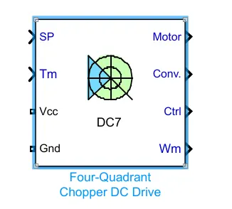
Inputs and outputs:
Armature voltage ,speed referance ,motor torque referance are given as inputs.
Motor,convertor,controller,motor angular speed are get as outputs.
Working:
- Here Four Igbt switches are used.
- Here pulses are given from PI current controller, that controles the pulses by comparing armature current measurement and current referance.
- Current referance can be generated by using regulation switch in that torque referance and PI speed controller pulses,that internally compared by speed of motor and refrance speed given as input.
- Mainly speed controlled by current controller.
- In this case Four quadrant operations are performed.
- Forward motoring mode,forward regenerative breaking mode: Q1,Q4 are on and Q2,Q3 are in off.
- Reverse motoring mode,reverse regenerative breaking mode: Q2,Q3 are on and Q1,Q4 are in off.
Comparisons:
- In DC7 chopper model speed controlled by varying current pulses from PI current controller and in H-brige model speed controlled by varying duty cycles voltages.
- Here regenerative breaking in occring while in H-bridge model breaking is occured by changing polarity of current flow,dynamic breaking occurs in it.
- In four quadrant DC chopper model smoothing inductance is used for smooth increase and decrease in current flow which inturns controlling the motor speed smoothly,while in
- H-bridge it is not present.
- Here the operation is discreat and in H-bridge model it is continuous.
- Hence 4 quadrant DC choppers are used mostly in electric vehicles.