Week-7 Challenge: DC Motor Control
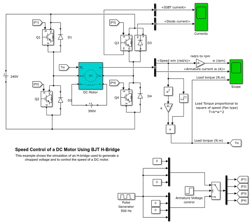
‘Speed control of a DC motor using BJT H-bridge’.
Working -
a. In the circuit, the input voltage is generated from the pulse generator where the amount of supply and duty cycle is assigned in PG.
b. Then the switch block is connected to pulse generator through an armature voltage control block.
c. The H - bridge consists of 4 BJT/ Diode pairs.
Q1, Q2, Q3 & Q4.
Two transistors are switched simultaneously: Q1 and Q4 or Q2 and Q3.
d. When Q1 and Q4 are lit, a positive voltage is given to the motor, and when Q1 and Q4 are turned off, diodes D2-D3 function as free-wheeling diodes.
e. When Q2 and Q3 are lit, a negative voltage is given to the motor, and when Q2 and Q3 are turned off, the diodes D1 through D4 function as free-wheeling diodes.
f. A switch block at the bottom of circuit splits the power supply into 4 parts - (p1,p2,p3,p4)
SWITCHES -
Forward motoring - Q1 and Q4
Reverse motoring - Q2 and Q3
1. DC motor is connected to a battery.
2. The output of the DC motor is connected with the BUS sector where speed is plotted in the scope.
B. Comment on the armature current shoot-up from the scope results.
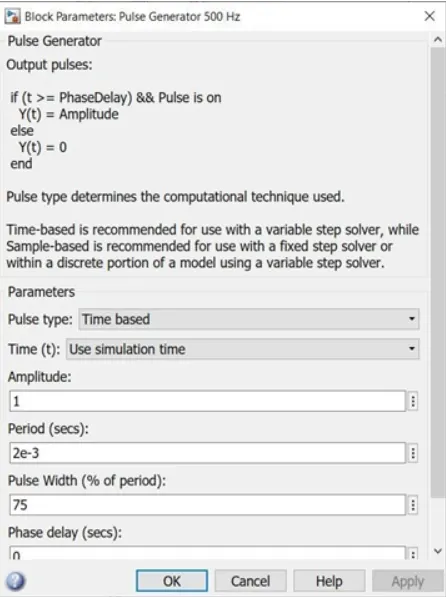
The pulse width was 75 in the pulse generator.
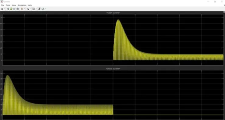
The scope shows the IGBT current and diode current passed in the quadrant Q3 and D3.
The graph shows that when the switch Q3 is OFF on the starting stage of current flow and diode current is on that stage.
During the 0.5 sec of time, D3 switch is ON that are given according to the pulse generator, and after the time period of 0.5 sec D3 switch is OFF and the IGBT current is acted after 0.5 sec and Q3 switch remains ON.
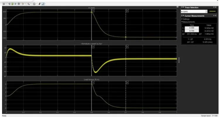
The speed and armature current is obtained by the DC motor and Load torque is calculated by torque proportional to the square of speed.
At the starting point, there is a sudden shoot-up.
This scope shows that speed is increased in a certain period of time and at that time armature current is positive whereas Load torque also moves forward.
BY CHANGING THE PULSE GENERATOR INPUT VALUE
By opening the pulse generator we can change the pulse width i.e the input value to whatever desired. So here we change the value to 50%.
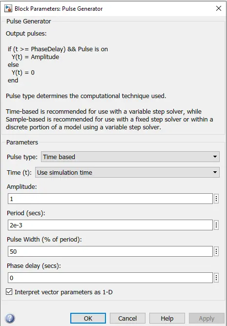
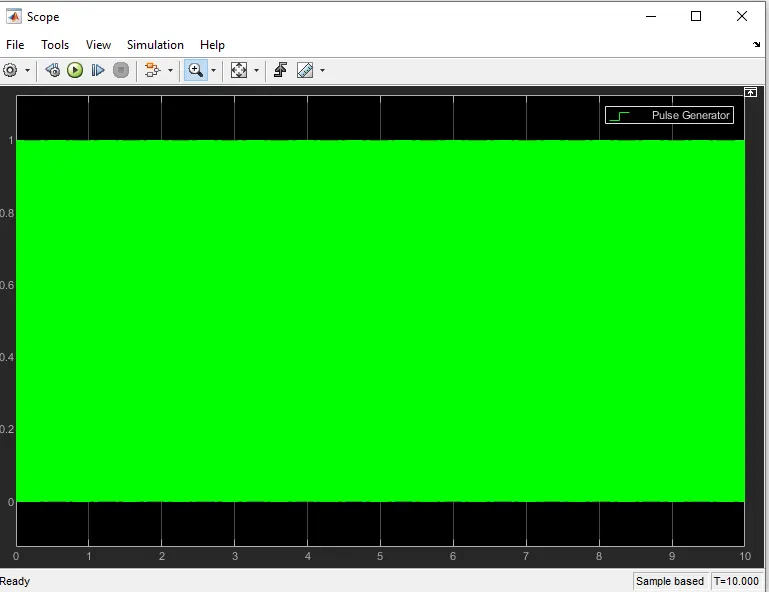
In this above scope, a flow of armature current is displayed and speed load torque is also displayed.
The change is made in pulse width as 50% from the pulse generator and results are shown that voltage fluctuation is held in starting point of forwarding reverse state.
The sudden fluctuation is reduced in this experiment by reducing the pulse width of the input supply.
A change is also held in speed and load torque where the constant level of speed and torque is acted in above scope compared with the previous 75% of the pulse width.
A time period of forwarding and reverse action is maintained as same as the previous Duty cycle.
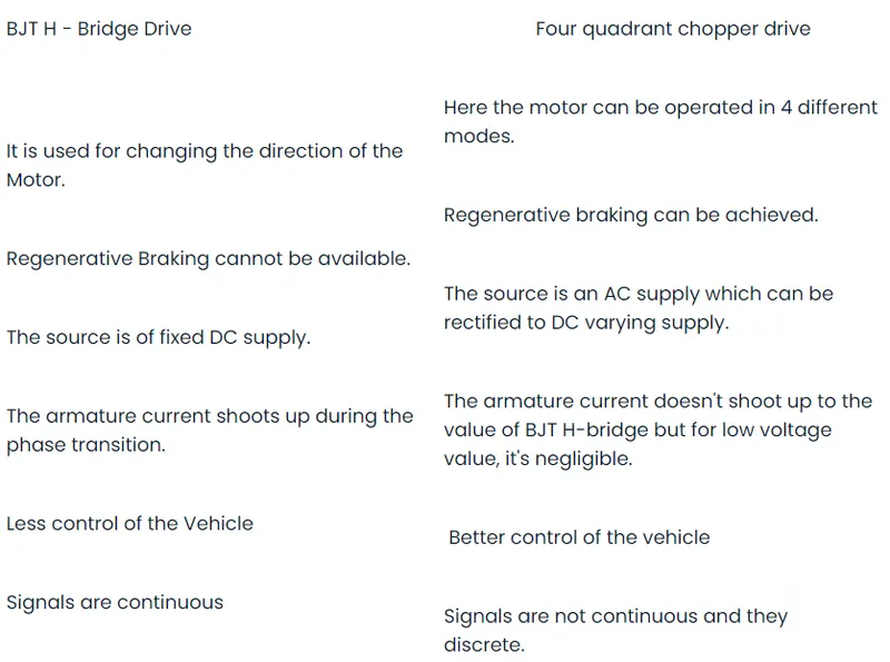
C. Refer to the help section of ‘The Four-Quadrant Chopper DC Drive (DC7) block’. Compare it with the H-bridge model.
Four Quadrant Operation of DC motor means that the machine operates in four quadrants. They are forward motoring, Forward braking, reverse motoring and reverse braking.
The Four-Quadrant Chopper DC Drive (DC7) block represents a four-quadrant, DC-supplied, chopper (or DC-DC PWM converter) drive for DC motors. This drive features closed-loop speed control with four-quadrant operation. The speed control loop outputs the reference armature current of the machine. Using a PI current controller, the chopper duty cycle corresponding to the commanded armature current is derived. This duty cycle is then compared with a sawtooth carrier signal to obtain the required PWM signals for the chopper.
The main advantage of this drive, compared with other DC drives, is that it can operate in all four quadrants (forward motoring, reverse regeneration, reverse motoring, and forward regeneration). In addition, due to the use of high switching frequency DC-DC converters, a lower armature current ripple (compared with thyristor-based DC drives) is obtained. However, four switching devices are required, which increases the complexity of the drive system.
2. Develop a 2-quadrant chopper using simulink & explain the working of the same with the relevant results.
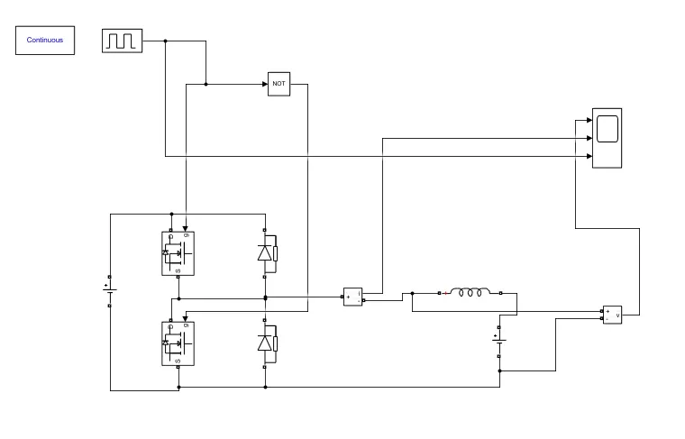
WORKING
Blocks use for the model
- Power GUI
- Voltage measurement Block
- Current measurement block
- DC voltage source
- MOSFET
- Pulse generator
- Diode
- Series RLC band
- Logical Operator
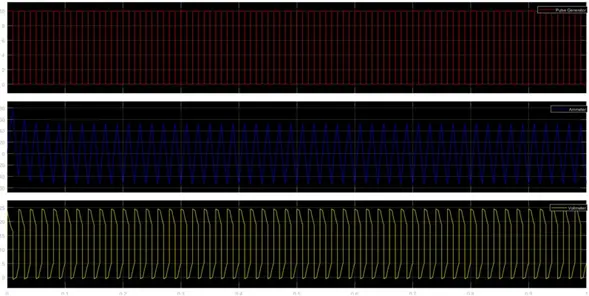
- The Two - quadrant chopper DC drive block represents a two-quadrant, DC - supplied, chopper drive for DC motor.
- This drive features closed-loop speed control with a two-quadrant operation. The speed control loop output the reference armature current of the machine. Using a PI current controller, the chopper duty cycle corresponding to the commanded armature current is derived.
- The main advantages of this drive, compared with other DC drives, are its implementation simplicity and the that it can operate in two quadrants. In addition due to the use of a high switching frequency DC-DC converter, a lower armature current ripple is obtained.
3. Explain in a brief about operation of BLDC motor.
- A brushless DC electric motor (BLDC motor or BL motor), also known as an electronically commutated motor (ECM or EC motor) or synchronous DC motor, is a Synchronous motor using a direct current (DC) electric power supply.
- It uses an electronic close loop control to switch DC currents to the motor winding producing magnetic fields which effectively rotate in space and which the permanent magnet rotor follows.
- The controller adjusts the phase and amplitude of the DC pulses to control the speed and torque of the motor. This control system is an alternative to the mechanical commutator (brushes) used in many conventional electric motors.
Construction BLDC motor -
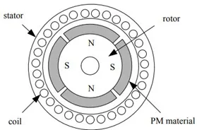
- The main design difference between brushed and brushless motors is the replacement of a mechanical commutator with an electric switch circuit. Keeping that in mind, a BLDC motor is a type of synchronous motor in the sense that the magnetic field generated by the stator and the rotor revolve at the same frequency.
- Brushless Motors are available in three configurations: single-phase, two-phase, and the ee-phase. Out of these, the three-phase BLDC is the most common one.
The following image shows the cross-section of a BLDC Motor.
Working Principle -
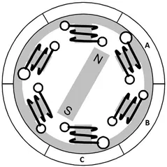
- Consider the following setup of three windings in the stator designated A, B, and C. For the sake of understanding, let us replace the rotor with a single magnet.
- We know that when a current is applied through a coil, a magnetic field is generated and the orientation of the field lines
i.e. the poles of the generated magnet will depend on the direction of the current flowing through the coil.Using this principle, if we supply current to coil A so that it will generate a magnetic field and attract the rotor magnet. The position of the rotor magnet will shift slightly clockwise and will align with A.
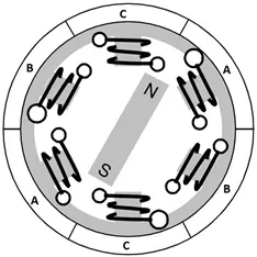
- To increase efficiency, we can wind the opposite coils using a single coil so that we get a double attraction. Further increasing the efficiency, we can energize two coils at the same time so that one coil will attract the magnet and the other coil will repel it. During this time, the third will be idle.
If we now pass current through coils B and C one after the other (in that order), the rotor magnet will rotate in the clockwise direction. - For a complete 3600 rotation of the rotor magnet, six possible combinations of the coils A, B, and C are applicable and are shown in the following timing diagram.
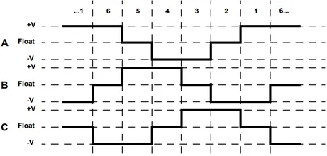
- Base on the above diagram, we can confirm that at any time, one phase is positive, one phase is negative and the third phase is idle (or floating). So, based on the inputs from the Hall Sensors, we have two switches in the phases as per the above diagram.
Driving Brushless DC motor -
- If stator and rotor are essential parts of a BLDC Motor that are integral to it, then the driving electronics are equally essential. A Block diagram of a typical Brushless DC Motor control or drive system is shown in the following image.
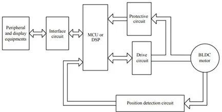
- This drive circuitry is often known as Electronic Speed Controller System or simply an ESC. One common setup is called the Full-Bridge Drive Circuit. It consists of an MCU with PWM outputs, six MOSFETS for the three phases of the stator windings, feedback from the Hall sensors, and some power supply-related components.
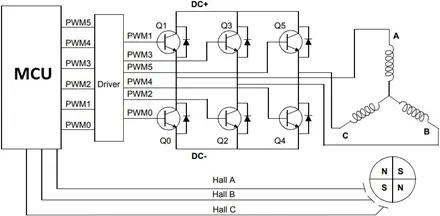
The MCU can be programmed to appropriately switch the MOSFETS based on the data from the Hall Sensors.
Advantages of BLDC motor -
Since BLDC Motors are electronically commutated, there are several advantages over traditional Brushed DC Motors. Some of them are:
No wear and tear (due to absence of brushes) High efficiency
Better speed vs torque characteristics Long life
Less noise or noiseless operation Significantly higher RPM
Application of BLDC motor -
Some of the areas of applications of BLDC Motors are mentioned below: Single-speed applications
Adjustable speed applications
Position control
Low noise applications High-speed applications
Conclusion -
From this work, we can conclude that we have understood the significance and importance of the DC motor control, the working and construction of the BLDC motor.