Week-7 Challenge: DC Motor Control
Aim: 1. Run MATLAB demo ‘Speed Control of a DC motor using BJT H-bridge’. Modify the model such that armature current doesn’t shoot up when motor changes direction from forward to reverse.
- Refer to help section of ‘The Four-Quadrant Chopper DC Drive (DC7) block’. Compare it with H-bridge model.
- Make a suitable EV model using DC7 block and make result report.
Solution 1: A bipolar junction transistor (BJT) is a type of transistor that uses both electrons and electron holes as charge carriers. In contrast, a unipolar transistor, such as a field-effect transistor, use only one kind of charge carrier. A bipolar transistor allows a small current injected at one of its terminals to control a much larger current flowing between two other terminals, making the device capable of amplification or switching. BJTs use two junctions between two semiconductor types, n-type and p-type, which are regions in a single crystal of material. The junctions can be made in several different ways, such as changing the doping of the semiconductor material as it is grown, by depositing metal pellets to form alloy junctions, or by such methods as diffusion of n -type and p-type doping substances into the crystal.
One type of bipolar transistor, the IGBT (Insulated Gate Bipolar Transistor) is an extremely robust power transistor ubiquitous in high power-switching applications such as in variable-frequency drives (VFDs) controlling the largest electric motors, electric cars, trains, variable speed refrigerators, elevators, high power and large scale lighting control, and others.
The bipolar junction transistor when used for power switching application operates as an IGBT. When it is conducting, a forward voltage is developed between collector and emitter. Thus IGBT block can be used to model the BJT device.
The IGBT block doesnot simulate the gate current controlling the BJT or IGBT. The switch is controlled by SIMULINK signal. The DC motor uses the present model (5HP 24V 1750 RPM). A fan type load is been simulated where load torque is proportional to the square of speed. The armature mean voltage can be varied from 0 to 240V when the duty cycle (specified in the pulse Generation block) is varied from 0 to 100%
The H-bridge consists of four diode pairs. Two transistor are switched simultaneously:
Q1 and Q4 or Q2 and Q3
When Q1 and Q4 are fired, a positive voltage is applied to the motor and diodes D2-D3 operates as a freewheeling diodes when Q1 and Q4 are switched off.
When Q2 and Q3 are fired , a negative voltage is applied to the motor and diode D1-D4 operated as free wheeling diodes when Q2 and Q3 are switched off.
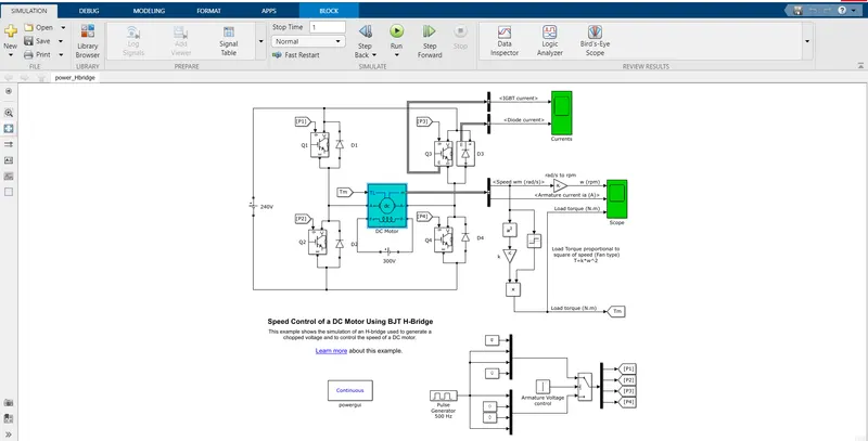
Case 1:
‘Speed control of a DC motor using BJT H-bridge’- 5Hp 240V 1750 RPM
Field Voltage =300
Torque TL Mechanical input
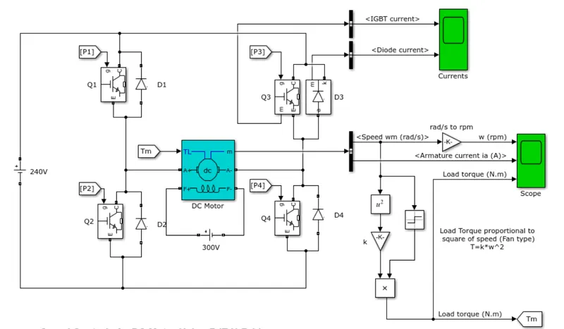
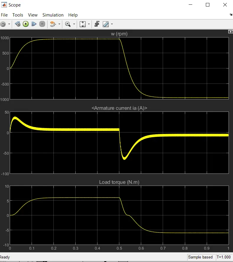
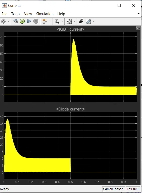
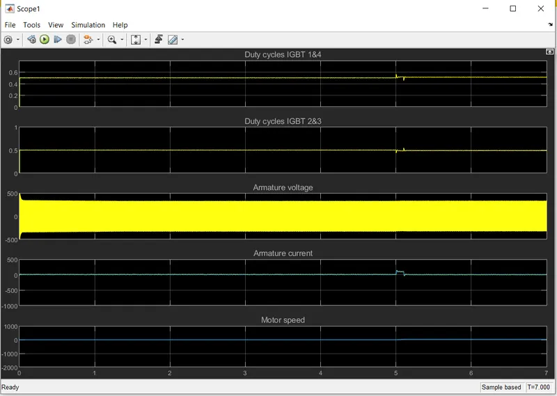
Case 2:
‘Speed control of a DC motor using BJT H-bridge’ 5HP 240 V 1750 RPM
Field Voltage= 150
Torque TL Mechanical Output.
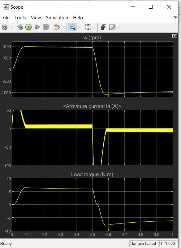
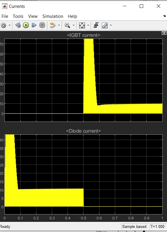
Solution 2:
The Four Quadrant Chopper DC drive represent a four quadrant DC-supplied chopped drive for DC motors. This drive features closed loop speed control with the four quadrant operation.
The main advantage of this drive, compared with other DC drives, is that it can operate in all four quadrants (forward motoring, reverse motoring, forward regeneration, reverse regeneration). In addition, due to the use of high switching frequency DC-DC converters, a lower armature current ripple (compared with thyristor-based DC drives ) is obtained. However four switching devices are required, which increases the complexity of the drive system.
The four quadrant chopper DC Drive block uses these blocks from the electric drives
Speed Controller (DC)
Regulation Switch
Current Controller (DC)
Chopper
H-bridge model
The H-bridge block represents a H-bridge motor driver. The block has the following two simulation mode of operation
PWM- The H-bridge block output is a controlled voltage that depends on the input signal at the PWM port. If the input signal has a value greater than the enabled threshold voltage parameter value, the H-Bridge block output is on and has a value equal to the value of the Output voltage amplitude parameter. If it has a value less than the enabled threshold voltage parameter value, the block maintains the load circuit using one of the following three freewheeling mode operation:
One semiconductor switch and one freewheeling diode
Two freewheeling diode
Two semiconductor switches and one freewheeling diode
Averaged- this mode has two load current characteristics option
Smooth
Unsmoothed or discontinuous
Comparison
Four Quadrant Chopper DC Drive DC7 block
- Used for automotive application for controlling DC motor speed and direction
- Regenerative braking is possible in DC7
- It can operate in all 4 quadrants of DC motors
- Only DC-DC converters high switching frequency is possible
- It has a wider range of torque and output power
H-Bridge
- Generally used in Robotics & Electro-mechanical devices for controlling the DC motor Speed and direction
- Dynamic braking is possible
- It can only operate in forward and reverse directions
- It shows the simulation value in accurate mode
- It has a narrow torque and output power
Solution 3: -
To load an EV using DC7 we use the search bar to open the model.
A Four Quadrant Chopper 200 HP DC Drive setup will open.
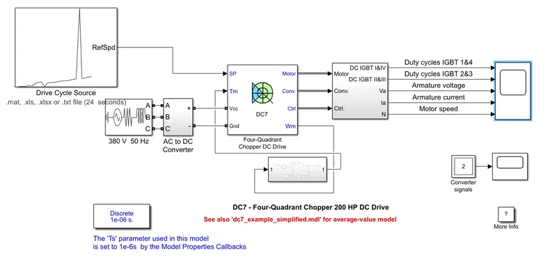
results for
The speed reference and linear load torque needs to be modified in the setup screen.
Now in the subsystem, we have to create a vehicle drive condition.
Following blocks are added to create a subsystem
Math function
Product
Sum
Euler’s number
Constants
We need to use 24.7+0.0051w^2 in the given block for further solution.
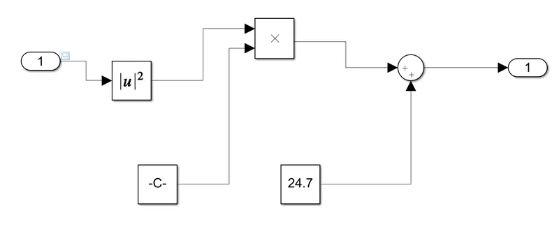
By using default speed reference we will get the output as shown in the proceeding output page
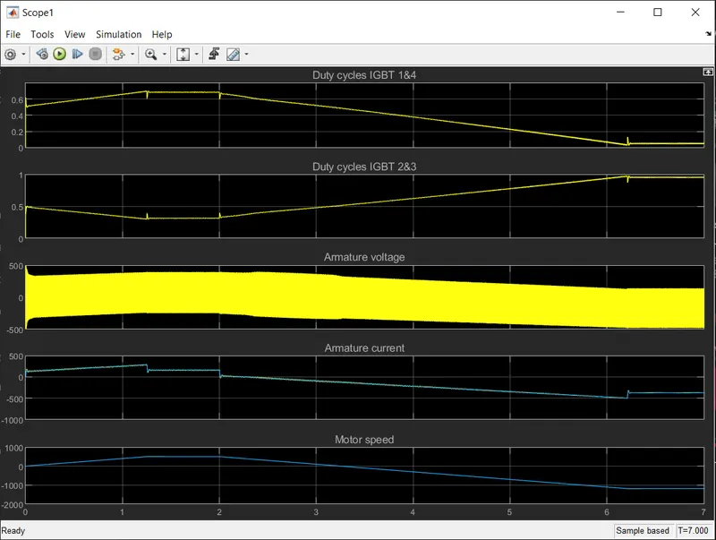
In the following step we create a drive cycle which will be added to the existing drive cycle
A speed vs 24 sec time drive cycle is created and it will be used as new drive cycle.
The results are
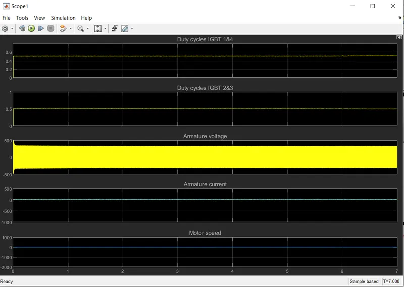
By using wide open throttle drive cycle we get the following results