Week-7 Challenge: DC Motor Control
Ans.1- In the model named 'Speed control of DC motor using BJT H-bridge'.
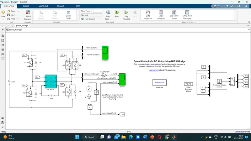
- Four switches are used and for providing the gate pluse four pulses are given to them.
- Here H- bridge DC chopper circuit is designed to control the speed of the motor. IGBT acts as BJT in power switching devices.
- Four IGBT switches are used for inverting the input voltage. The current flows from collector(C) to Emitter(E).
- The gate are controlled by the pulses according to the armature voltage of motor given by pulse generator.
- Armature voltage given in steps to attain final speed. Here for each switch a pulse is given like for Q1, P1 is the pulse and simlarly Q2,P2 then Q3,P3 and Q4,P4.
- In first state Q1 and Q4 switch is ON by providing pulse and diode D2 And D3 are used as free wheeling diode in this state. Only forward motoring and forwardbreaking are held.
- In Second state Q2 and Q3 are ON and Diode D1,D4 are used as free wheeling diode in this state.
- Free wheeling diode are used as a safety purpose of this inverter circuit, when ever the switch changes the remaining current by pass through that Diodes and also it can handle the Voltage fluctuations.
- The motor armature terminals are connected with a 240V along the inverter circuit and field winding are connected with 300 V DC supply to act as a electro magnets for the motor.
- The load torque is provide to the motor for its referance. Thus the Magnetic fields generated, variable current carring conductors in rotor armature produces forces and the motor will rotate.
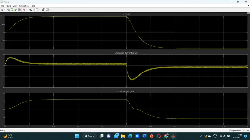
Speed of the motor:
Speed goes upto 900 rpm in just 0.5 sec as a Forward Motoring action. Then goes to 0 as braking is applied in just 0.55sec. Then goes -900rpm as reverse motoring mode is happening.
Load torque of motor:
Initially torque increase from 0 to 0.5 sec in forward motoring action. Then goes to zero in forward dynamic braking .Then in reverse motoring mode torque increases again.
B). Armature Current shoot up in motor:
- Here the inital current shoot up is due to sudden increase in voltage which regulates on duty cycle. then the current goes constant till 0.5 sec as forwardmotoring mode is ON
- Then on appling brakes the current sudden deplets and a negative current shoots happen and motor enters in reverse mode and we get negative constant current till 1sec.
- If we change the duty cycle from 75% to 50% . The sudden shoot up canceled in starting condition but slight shootup after 0.5 sec in reverse motoring condition.
- So, on decreasing duty cycle The shoot of current get dimlished on both the ends .
C). Compare with the H-bridge model. ‘The Four-Quadrant Chopper DC Drive (DC7) block’:
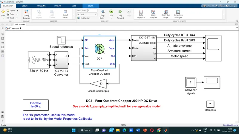
Here, Four- Quadrant Chopper DC Drive block uses these blocks from the Electric Drive/Fundamental Drive Blocks Library.
- Speed Controller(DC)
- Regulation Switch
- Current Controller(DC)
- Chopper.
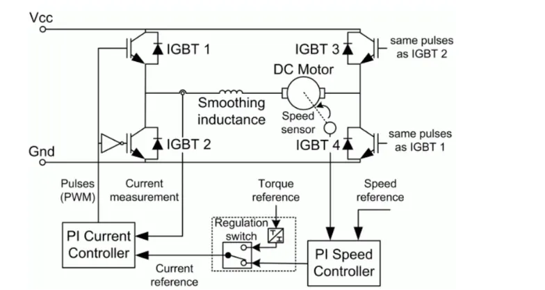
- Here Four IGBT switches are used, Here pulses are given from PI controller, that controles the pulses by comparing armature current measurement and current referance.
- Current referance can be generated regulation switch in that torque referance and PI speed controller pulses, that internally compared by speed of the motor and the referance speed given as input.
Here Four quadrant operations are performed.
- forward motoring mode and forward regenerative braking mode: Q1,Q2 are on and Q2,Q3 are Off.
- Reverse motoring mode, reverse regenerative breaking mode:Q2,Q3 are on and Q1,Q4 are in Off.
Comparisons:
- The four quadrant chopper have high switching frequency as compare to H-bridge.
- The four quadrant chopper works in all four modes like
- forward motoring & forward breaking
- reverse braking & reverse breaking
3.But in BJT h_bridge model it works in only two modes
- forward motoring & reverse motoring
4. Four qudrant chopper is generally used in industrial application while H-bridge model is used in robotics.
5.To change the direction of rotation of motor from forward to reverse and vice versa , the current signals get transited from one to other switch while in h bridge model, the direction of rotation of motor is changed by changing the polarity of current.
Ans2. 2-quadrant chopper:
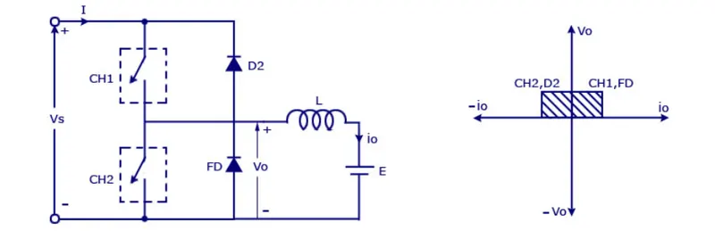
Two quadrant chopper is also called C type chopper. We will get +ve voltage all the time because it operates in 1st and 2nd qurdant only .
Here two switches and two diodes are used. The power flow may be like the first qudrant operation either from sourse to load or from load to source in second qudrant operation. The two choppers should not be turned on simultaneously as the combined action may cause a short circuit in supply lines.
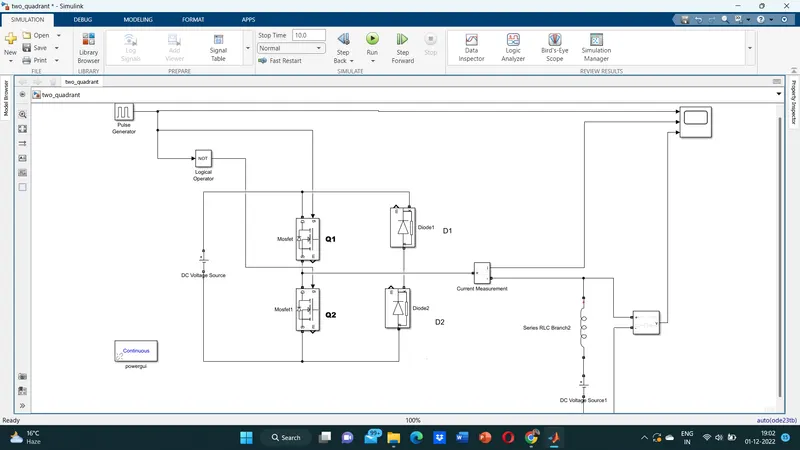
- Here Switch 1st mosfet or 2nd mosfet, either one should be ON at a time. If Q1 is ON the current floes from source +ve to Load(here DC motor), Passes Through -ve terminal of source. (1st quadrant)
- Then if Q2 is ON ,Current flow from Load to source and regenerative breaking occurs(2nd Quadrant).
ANS.3- A BLDC electric motor is a synchronous DC motors, it is powered by direct current(DC) electricity via an inverter or switching power supply which produces electricity in the form of alternating current(AC) to drive each phase of the motor via a closed-loop controller. The controller provides pulses of current to the motor windings that control the speed and torque of the motor. This control system replaces the commutator(brushes) used in many conventional electric motors.
The construction of a brushless motor system is typically similar to a 'PMSM', but can also be a switched reluctance motor, or an induction(asynchronous) motor.
They may also use neodymium magnets and can be a
- Outrunners (the stator is surrounded by the rotor)
- In runners (the rotor is surrounded by the stator)
- or axial (the rotor and stator are flat and parallel)
Operation of BLDC motor:
We can consider three winding trminal are comming out as U,V,W and their another ends are connected in single point as shown in below figure.The angle shift between two coils makes 120 degree.
The current moves from U to W makes magnetizing the coils attracts the rotor consisting of permanent magnet makes moment as shown above to align with the resultant.
North pole of magnet towards arrow mark of resultant arrow.
Rotation is maintained by continually switching the flux so that the permanent magnet is constantly chasing the rotating magnetic field induced by the coils. In other words, energizing of U, V, and W must be continually switched so that the resultant flux keeps moving, producing a rotating field that continually pulls on the rotor magnet.
The above movement are acheived by continuous change in current direction over two poles of stator at single time.But this is slightly not continuous in their rotation.This makes motor vibration and noice will be produced.
So, to attain smooth continuous rotation of rotor we have to control the current flow through all the three poles in same time.
As the result we can acheive continuous change in current flow in all stator poles at same time in 120 degree phase shift. As we have seen, we drive BLDC motors by continually changing the directionality of the flux produced by the coils. The permanent magnets on the rotor continually chase the shifting rotating magnetic field,causing the rotor to turn.So,this is the working of BLDC motor.
The advantages of a brushless motor over brushed motors are as follows:
High power-to-weight ratio, high speed, electronic control, and low maintenance. Brushless motors uses in computer peripherals (disk drives, printers), hand-held power tools, and vehicles ranging from model aircraft to automobiles. In modern washing machines, brushless DC motors have allowed replacement of rubber belts and gearboxes with a much simpler way.