Week-7 Challenge: DC Motor Control
1) Explain a MATLAB demo model named peed control of a DC motor using BJT H-bridge’
Aim ) The main aim is to explain the speed control of the dc motor by using the BJT h bridge in Matlab
H- bridge
The H bridge is a rather simple circuit containing four switching elements with the load at the center in an H-like configuration
A H bridge is essentially four switches that allow the polarity of the supply applied to a motor to be attached
both ways round. Thus, the motor can be driven both clockwise or counter clockwise.
he engagement of the switches has to be carfully implemented as an enabling a high and low side pair result in a short circuit of the power source something that reaally end well
Therefore the designer has to ensure that only diogonally opposed pair of high / low side switches can be engaged at any moment in time
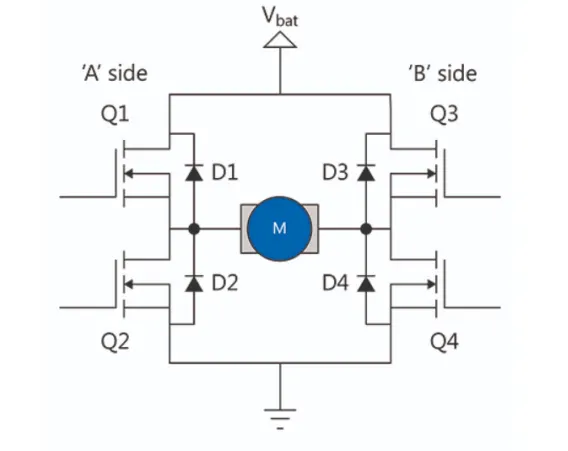
Basic operation of H- bridge
FORWARD OPERATION
'
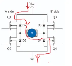
in this operation the switching flow is (Q1-D1-M-D4-Q4)
that means the Q1 switches is high polarity and q4 switches become low polarity then the bridge circuit act as forward direction
reverse operation
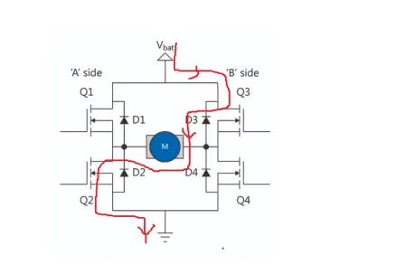
IN this operation the switching flow is ( Q3-D3-M-D2-Q2), that means the q3 switches is high polarity and q2 switches become low polarity then the bridge circuit act as reverse direction
MATLAB demo model named ‘Speed control of a DC motor using BJT H-bridge:-
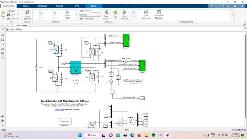
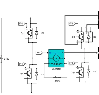
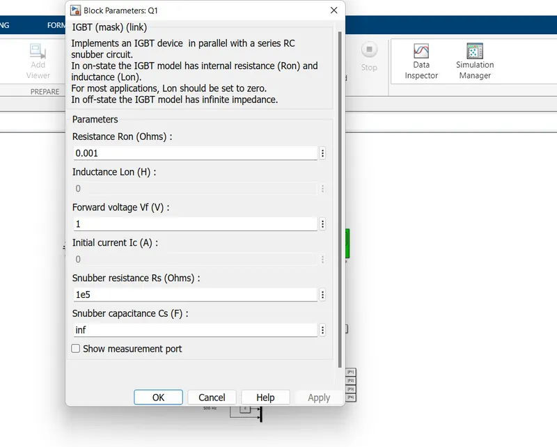
The Bipolar Junction Transistor (BJT) when used for power-switching applications, operates as an IGBT. When it is
conducting (BJT operating in the saturated region), a forward voltage Vf is developed between the collector and emitter (in
the range of 1 V). Therefore, the IGBT block can be used to model the BJT device.
The IGBT block does not simulate the gate current controlling the BJT or IGBT. The switch is controlled by a
Simulink signal (1/0).
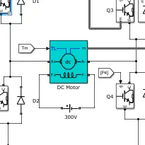
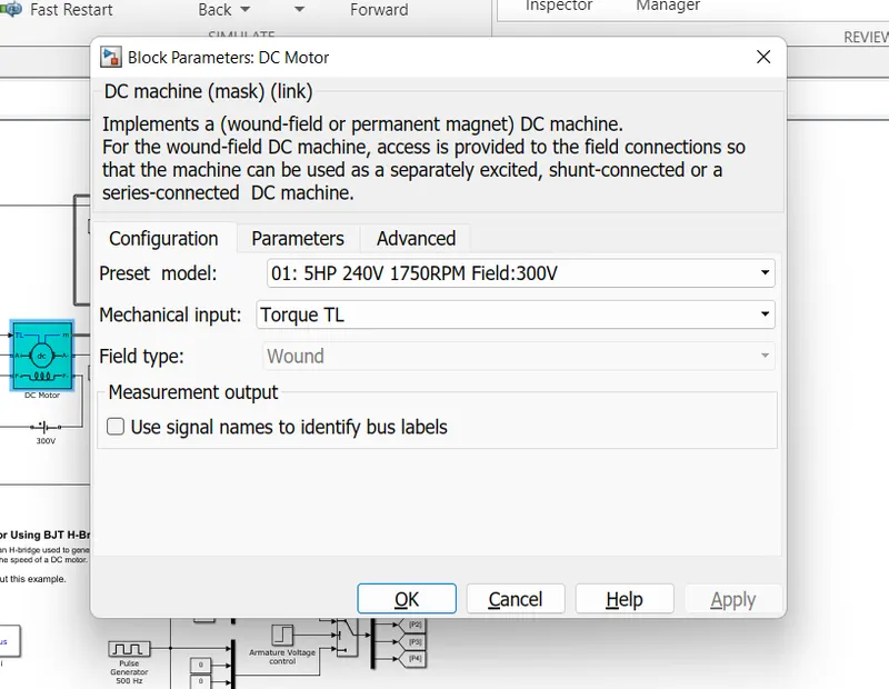
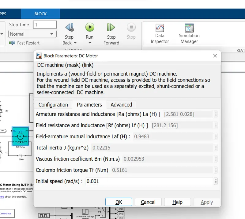
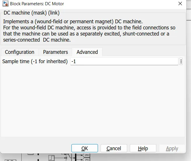
DC Motor block parameter
pulse width modulation
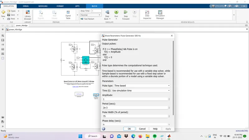
Pulse Width Modulation(PWM) is a modulation technique that generates variable-width pulses to represent the
amplitude of an analog input signal. The length of time that a pulse is in a given state (High/Low) is the "width" of a pulse wave. Here the term comes the duty cycle which represents percentage values.
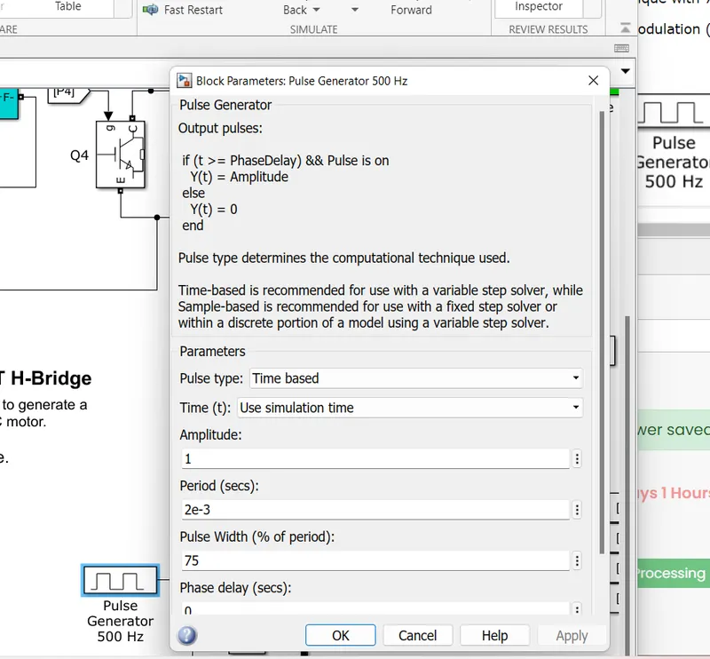
The Pulse generator is given by a pulse width of 75% and a period of 2e-3 seconds.The motor parameters of the
torque and field voltage and armature voltages are taken as default values of the mode
RESULT
BJT and Diode currunt plot
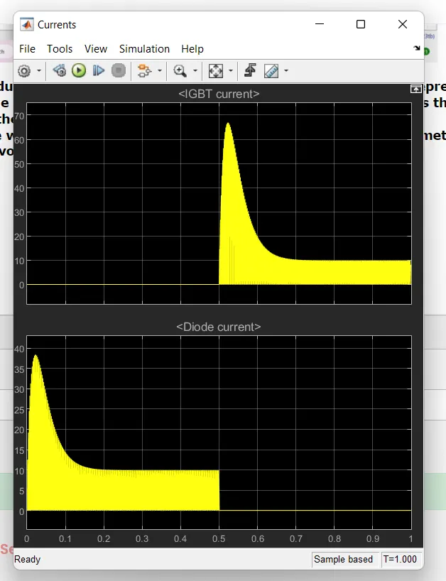
>>From the above scope the top scope is regarding BJT currents and bottem scope is for Diode Currents.
>> We can observe that the During the 1 sec period of cycle upto 0.5 sec the BJT gets no current output while Diode
consiste of 38 Amps nearly
>> after 0.5sec The diode showes 0Amps Currents but the BJt is acivated and peak current vakue at 0.52 sec is nearly 65
amps.
motor side plot
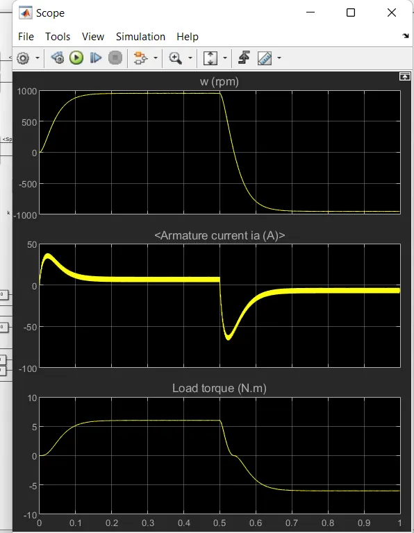
Top Plot for angular speed of the motor (W) in Rpm
From this grapgh we can observe that the dc motor gets accelaration from 0 to 1000 rpm within 0.5 sec and deceleration start from 0.5, at 0.6 sec the rpm start its negative direction and the motor speed becomes 100
Middle plot for armature currunt
from this graph, we can observe that the dc motor armature current (ia)is raised 0 to nearly 40 amps with intervals of 0 sec to 0.1 sec
after 0.1 sec -0.5 sec the armature currents between becomes very very low this can be seen in the above graph
bottom plot -load torque (Nm)
The load torque follows the speed waveform in the positive direction when the negative direction it follows the armature current and the speed waveform
conclusion
From using the BJT H- bridge controller the speed of the dc motor will be controlled
1)(b) comment on the armature current shoot-up from the scope results
Aim) The main is by using BJT H bridge to explain the armature current shoot up from the scope result
Armature current (ia)-The output of the armature current will basically depend on the input signal % duty cycle the armature current shoot up can be observed by following 2 types % of duty cycle cases
case1) The basic model of BJT H bridge uses the input signal as PWM technique with 75% of duty cycle
Pulse width modulation (PWM)
Block parameter
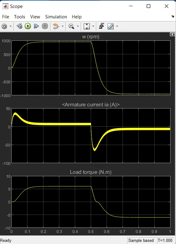
from this graph we can observe that the dc motor armature currunt (ia)is raises 0 to nearly 40 amps with interval of 0 sec to 0.1 sec
after 0.1 sec -0.5 sec the armture currunts between becoms very very low this can be seen in above graph
case (2) The model BJT H -Bridge uses the input signal as PWM technique with 50% of duty cycle
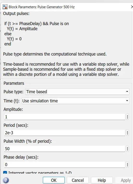
the output result plot
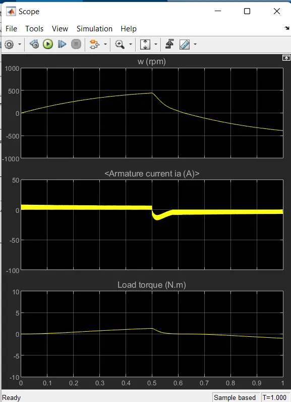
Middle plot for Armature currunt (Ia) -amp
The difference between two case(1) and case (2) graphs The rmature currunt in case (2) graph having no sudden rise at the starting of the armature currunt
if we further reduced the pulse width modulation the negative of the rise will get reduced
conclusion
with increase of the duty cycle % we can get the sudden rise in armature currunt in fraction of sec this sudden rise of armature currunt will be reduced by reducing the duty cycle
1)(c) Refer to the help section of the four quadrant chopper dc drive (DC7) block compare it with he H bridge model
Aim;The main aim is camparison between the four quadrant chopper Dc drive (DC7) block and H- bridge model
Chopper ;- A dc to dc converter also known as dc chopper is a static device which is used to obtain a variable dc voltage from a constant dc voltage source
chopper are widely used in trolley cars battery operated vehicle traction motor control,control of arge numbers of dc motor etc They are also as dc voltage regulator
two types of choppers ( based on output voltage)
1) step down chopper
2) step_ up chopper
Accpording to their working ( (four quadrant );-
we can classify chopper circuit as type A,typeB, type c, type D and type E.
type A;- the out put voltage and currunt both must be positve
type B;-The output of the voltage is positive and the currunt is negative
Type c;- the output voltage is positive and currunt can be either positive or negative
type D;- The out put currunt is positive and the voltage can be either positive or negative
type E;- the both output voltge and currunt can be either positive or negative
The four quadrant chopper dc drive (dc7) block;-
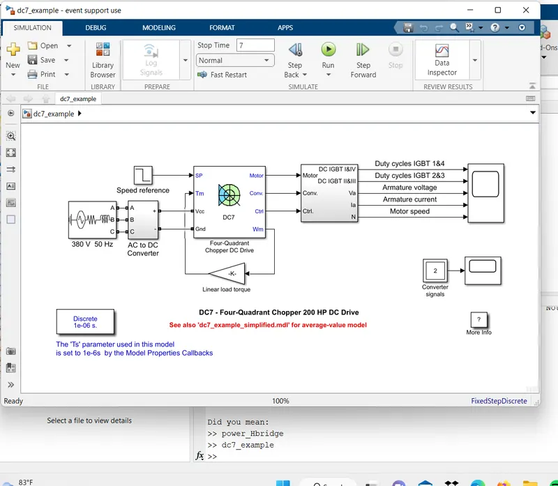
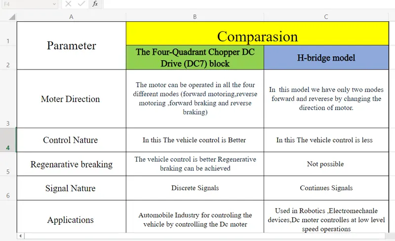
comparison between The four quadrant chopper sc drive (DC70 block and H-bridge model
comparison link=Comparision.xlsx - Microsoft Excel Online (live.com)
2.)develop a 2 quadrant chopper using simulink and explain the working of the same with the relevent reuslt
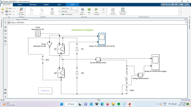
Aim;-The main aim is develop a 2 quadrant chopper using simulink
chopper;-
A dc - to- dc converter also known as dc chopper is a static device which is used to obtain variable dc voltage from constant dc voltage source
chopper are widely used in trolly cars battery operated vehicle traction motor controller control of large numbers of dc motors etc. They are also used as dc voltage regulator
Simulink model
output scope result
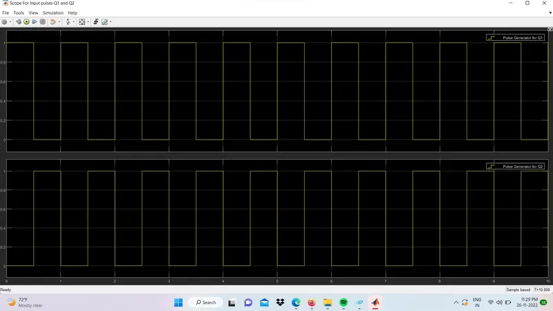
we can observe that the while q1 and q2 value is zero position
currunt and voltage plot
develop a 2 quadrant chopper using simulink and explain the working of the same with the relevent reuslt
Aim;-The main aim is develop a 2 quadrant chopper using simulink
chopper;-
A dc - to- dc converter also known as dc chopper is a static device which is used to obtain variable dc voltage from constant dc voltage source
chopper are widely used in trolly cars battery operated vehicle traction motor controller control of large numbers of dc motors etc. They are also used as dc voltage regulator
Simulink model
output scope result
we can observe that the while q1 and q2 value is zero position
currunt and voltage plot
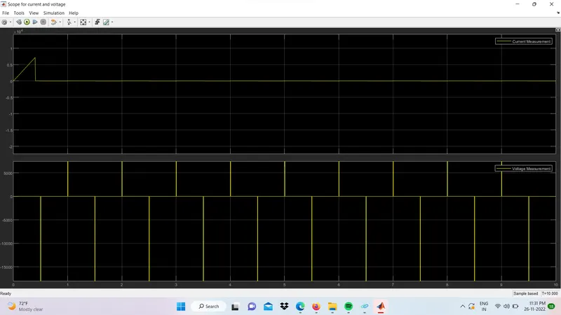
from above graph we can observe that top plote is currunt polt and bottom plot is voltage plot
currunt plot we can see that starting currunt gets a spike value 0.9 amps in between 0 sec to 0.9 sec
after that the currunt gets zero position
voltage plot we can see that the voltage spike in terms of pulses in load side
conclusion;-
2 quadrant chopper using simulink id developed and output scopes are explained
3) explain in a brief about operation of BLDC moter
3) explain in a brief about opertion of BLDC motor
Aim);- A BLDC Motor ( known as brushless dc motor)
is a permanent magnet synchronous motor which is driven by direct current (dc) electricity and it accomplishes an electronically controlled commutation system instead of a mechanical commutation system.BLDC motors are also referred as trapezoidal permanent magnet motors,
commutation is the process of producing rotational torque in the motor by changing phase current through it at the appropriate times
BLDC motors employ electrical commutation with a permanent rotor and a stator with a sequence of coils. in this motor permanent magnet rotates and current-carrying conductors are fixed
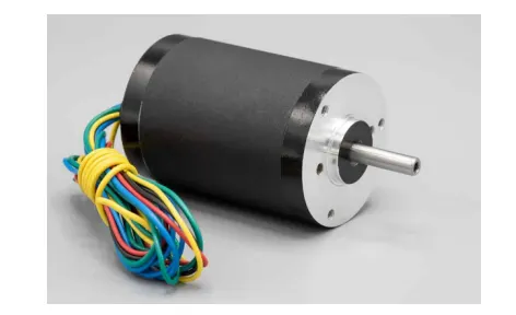
construction of BLDC MOTOR;-
BLDC motor can be constructed in different physical configuration. dependign on the stator winding these can be configured as single phase two phase or three phase motor. however three phase BLDC motor with permenent magnet rotor are most commonly used.
A commutator brushes arrangement helps in achieving unidirectional torque ina typical dc motor, commutator and brush arrangement is eliminated in a brushless dc motor
just like any other electric motor BLDC motor also consist of two main parts a stator and rotor
permenent magnet are mounted on te rotoe of a bldc motor
Stator construction
stator pf bldc motor made up of stacked steellamination to carry winding . these winding slots which are axially cut along the inner periphery of the stator . These winding can be arranged in their stator data however most BLDC Motor have three phase star connected stator
Each winding is constructed with numerous interconnected coil where one or more coils are placed in each slot in order to even number of poles
the stator must be chosen with the correct rating of the voltge depending on the power suppy capability
for robotics automative and small actuating application , 48v or less voltage BLDC motor re preffered for indstrial application ajd automobiles system,100v or higher motor rating motor are used
Rotor construction
BLDC motor incorparate a permenent magnet in the rotor.The number of poles in the rotor can vary from 2 to 8 poles pair with with aternate south and north pole depending on the application requirement
in order to achieve maximum torque in the motor the flux density of the material should be high magnet material for the rotor is needed to produce required magnet field density
ferrite magnet are inexepensive however they have a low flux desity for a given voluem Rare earth alloy are commonly used for new design.
The rotor canbe constructed with different core configeration such as the circular core with permanent magnet on the periphery, circular core with rectangular magnet etc.
WORKING PRINCIPLE
Ststor winding of a BLDC motor are connected to a control circuit ( an integrated circuit or inverter circuit).The control circuit energizes proper winding t the proper time in a pattern which rotates around tge stator.
permenent magnet on the rotor try to align with energized electromagnets of the statorand as soon align the next electromagnet are energized
The layout of a Dc brushless motor can vary depending on whether it is in outrunner style or inrunner style
INRUNNER
The stator is fixed drum in which the field magnet rottes. the motor is known for producing less torque thannthe out runner style but is capable of spining at vary high rpm
OUTRUNNER
The field magnet is a drum rotor which rotates around the stator. This style is preferred for applications that
require high torque and where high rpm isn’t a requirement.
advantages
1.less overll maintanance due to absence of brushes
2. Reduce size with far superior thermal charecteristics
3.higher speed range and lower electric noise generation.
4.it has no mechanical commutator and associated problems
5. high efficiency and high out put power to size ratio due to use of permenent magnet
Application
1. computer hard drives and dvd/cd layers
2. electric vehicle ,hybrid vehice and electric bicycle
3. industrial robots ,CNC machine tool
4.washing machines compressors and dryers.
5. fans , pumps and blowers
Conclusion;-The operation of BLDC motor is explained