Week-7 Challenge: DC Motor Control
Description –
The 200 HP DC motor is separately excited with a constant 150 V DC field voltage source. The armature voltage is provided by an IGBT converter controlled by two PI regulators. The converter is fed by a 515 V DC bus obtained by rectification of a 380 V AC 50 Hz voltage source. In order to limit the DC bus voltage during dynamic braking mode, a braking chopper has been added between the diode rectifier and the DC7 block.
The first regulator is a speed regulator, followed by a current regulator. The speed regulator outputs the armature current reference (in p.u.) used by the current controller in order to obtain the electromagnetic torque needed to reach the desired speed. The speed reference change rate follows acceleration and deceleration ramps in order to avoid sudden reference changes that could cause armature over-current and destabilize the system. The current regulator controls the armature current by computing the appropriate duty ratios of the 5 kHz pulses of the four IGBT devices (Pulse Width Modulation). For proper system behaviour, the instantaneous pulse values of IGBT devices 1 and 4 are opposite to those of IGBT devices 2 and 3. This generates the average armature voltage needed to obtain the desired armature current. In order to limit the amplitude of the current oscillations, a smoothing inductance is placed in series with the armature circuit.

The main advantage of this drive, compared with other DC drives, is that it can operate in all four quadrants (forward motoring, reverse regeneration, reverse motoring, and forward regeneration). In addition, due to the use of high switching frequency DC-DC converters, a lower armature current is obtained. However, four switching devices are required, which increases the complexity of the drive system.
Simulation –
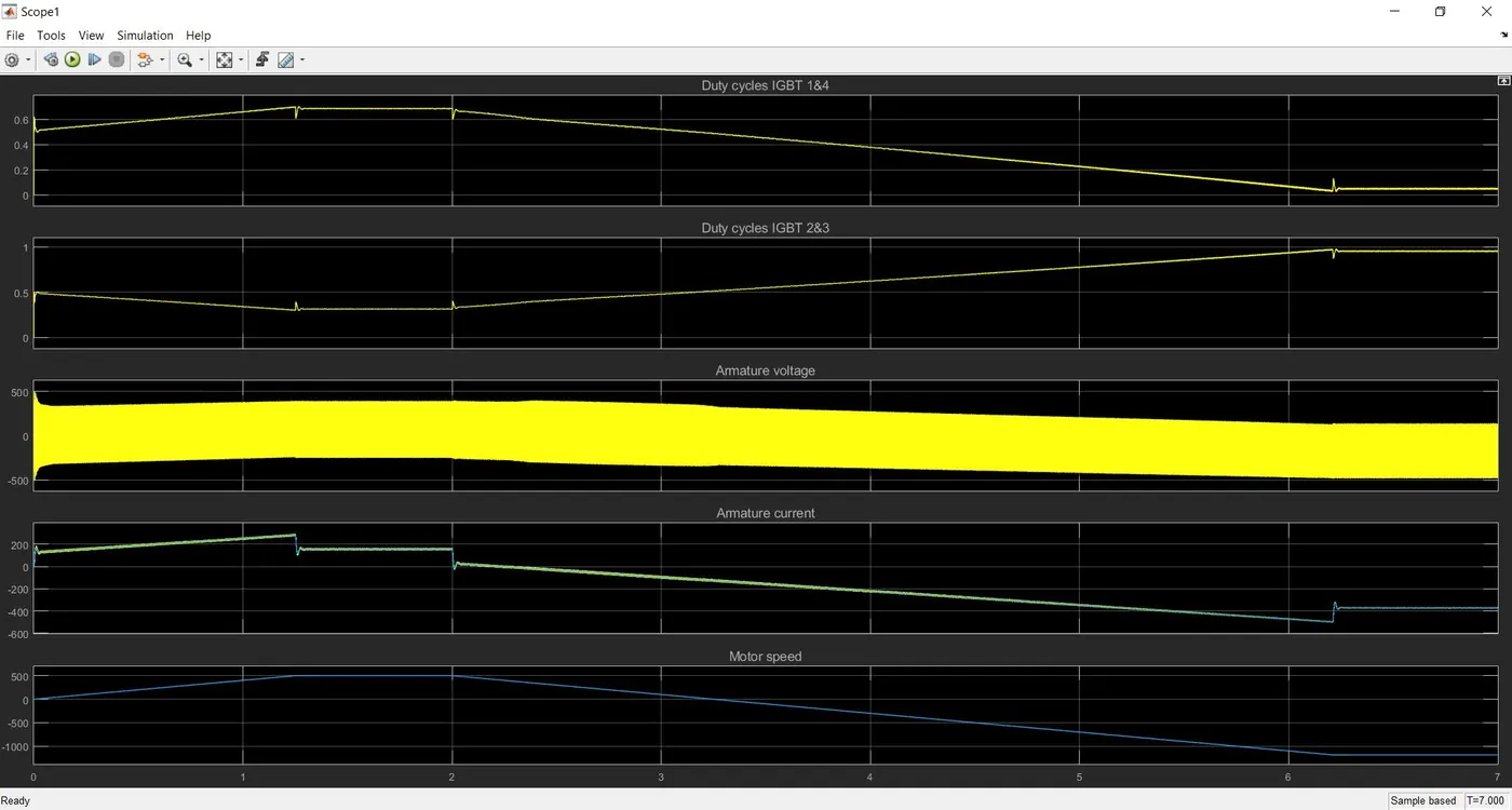
Based on the above simulation results, we can see that,
- The plot of duty cycles IGBT 1&4 are exactly opposite to that of duty cycles IGBT 2&3 as the pulse values of IGBT devices 1 and 4 are opposite to those of IGBT devices 2 and 3.
- The desired armature current is obtained from the average armature voltage.
- The armature current follows the current reference very well, with fast response time and small ripples.
Comparing the Four-Quadrant Chopper DC Drive (DC7) block with BJT H-bridge –
- In Four Quadrant Chopper DC Drive Block, the speed reference input is used to change the direction of the motor rotation whereas in BJT H-bridge model, the polarity is reversed to change the direction of motor rotation.
- In BJT H-bridge model, the motor can be controlled by changing the pulse width of the pulse generator whereas in Four Quadrant Chopper DC Drive Block, the speed reference values can be changed to control the motor.
- The Four Quadrant Chopper DC Drive operates in four modes wiz. forward motoring, forward regenerative braking, reversing motoring and reverse regenerative braking mode whereas BJT H-Bridge model operates only on two modes wiz. forward and reverse.
- PI (Proportional Integral) Controllers are used for speed and current control in DC7 block and it is absent in BJT H-bridge model.
- The Four Quadrant Chopper DC Drive Block uses ramps to avoid current shoot up and smooth working stability.
- The disturbances and current shoot up is high in H-Bridge model because of switching losses.
- This is why the overall performance and stability is good in Four Quadrant Chopper DC Drive comparing BJT H-Bridge model.
3. Make a suitable EV model using DC7 block and make result report.
To make a suitable EV model, we need to modify the DC7 block using Library Browser.
First we need to prepare our drive cycle data in excel file. Here we assume that our vehicle is running for 25 seconds.
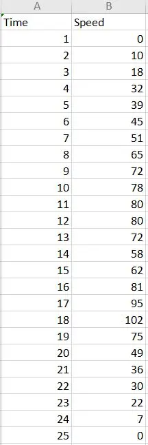
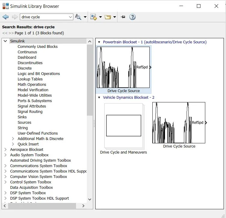
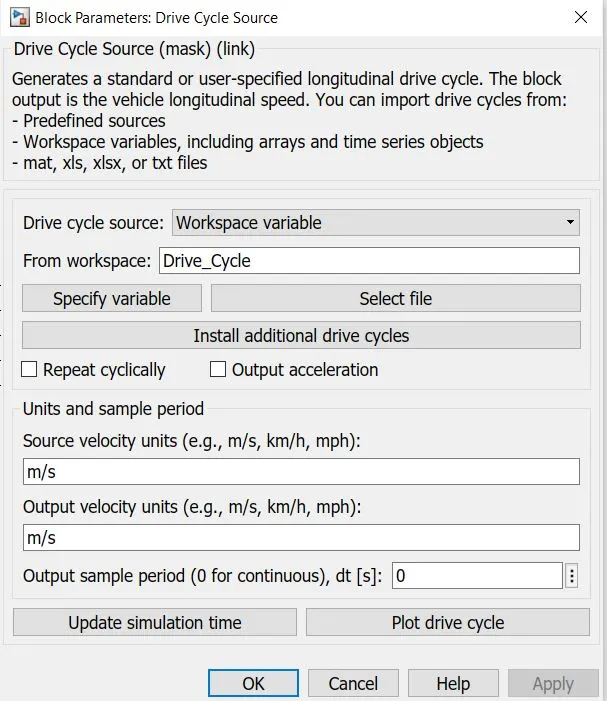
The Drive Cycle data is then imported to the workspace. Then we need to add Drive Cycle Block from Library Browser to DC7 model and in Drive Cycle Block, select the Drive Cycle Source as Workspace Variable.
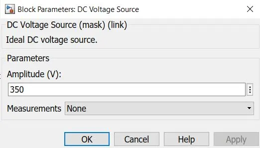
Now, as it is an EV, we need to add a DC source from the Library Browser. The DC Voltage value is set to be 350 V from reference.
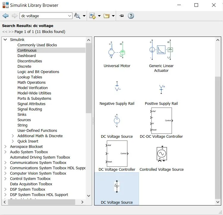
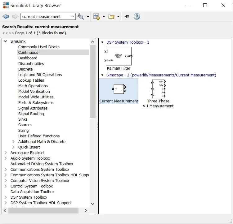
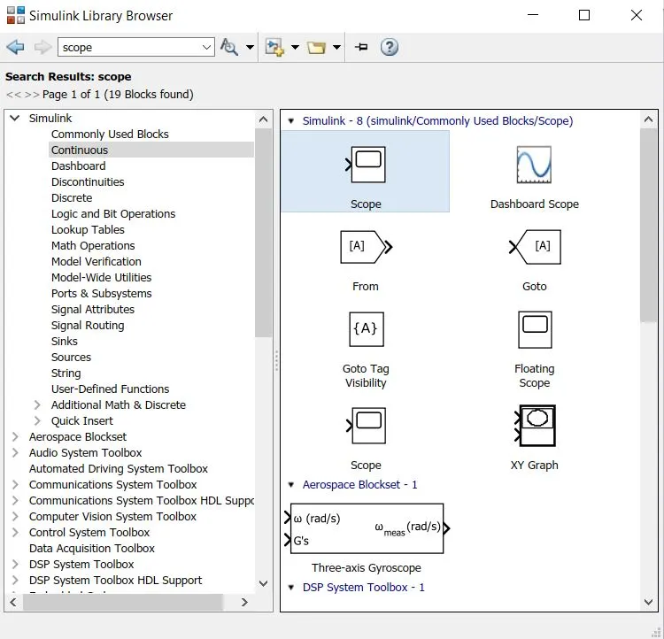
To measure the current from the DC source, a Current measurement block is placed between DC7 block and DC source block along with a scope.
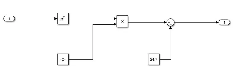
The Linear Load Torque will be replaced with a subsystem model according to the load characteristics given by,
TTR = 24.7 + 0.0051ω2ω2
We can model the above equation in Simulink as follows;
Select the Subsystem block,
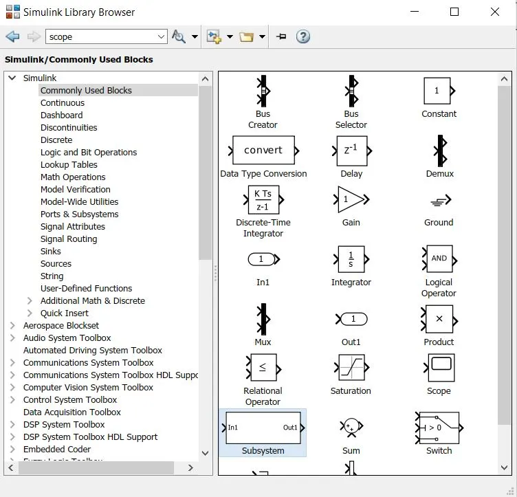
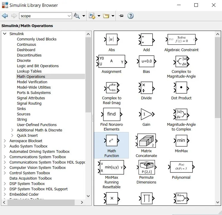
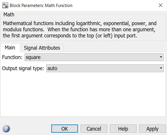
In the subsystem block, to resemble the equation select Constant, Product, Sum from commonly used blocks and Math Function from Math Operations blocks.
Model the Vehicle Load Characteristics equation as shown below;
The main EV model of DC7 block will look like;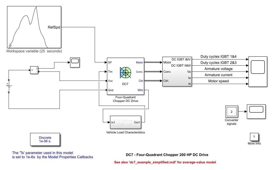
Now run the simulation. After running the simulation, we get the following results;
Plot and Result –
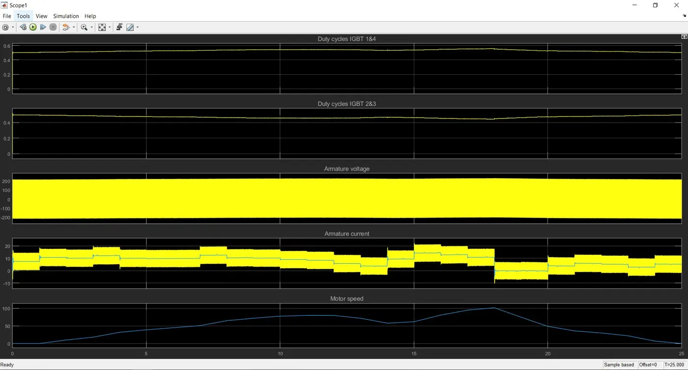
- The Duty Cycle plot of IGBT 1&4 follows the same relation as that of motor speed, i.e. it increases during acceleration and decreases during deceleration.
- The Duty Cycle plot of IGBT 2&3 follows the opposite relation to IGBT 1&4, thus with motor speed as the pulse values are opposite.
- The average armature voltage remains constant throughout the operation or experiences a negligible change.
- The armature voltage increases with increasing speed and decreases with decreasing speed