Week-7 Challenge: DC Motor Control
The Bipolar Junction Transistor (BJT) when used for power switching applications, operates as an IGBT. When it is conducting (BJT operating in the saturated region), a forward voltage Vf is developed between collector and emitter (in the range of 1 V). Therefore, the IGBT block can be used to model the BJT device.
The IGBT block does not simulate the gate current controlling the BJT or IGBT. The switch is controlled by a Simulink® signal (1/0).
MODEL DISCRIPTION:
1) dc motor used is model is preset model(5 HP 24V 1750 rpm) .It simulates a fan type load (where Load torque is proportional to square of speed). The armature mean voltage can be varied from 0 to 240 V when the duty cycle (specified in the Pulse Generator block) is varied from 0 to 100%.
2)The H-bridge consists of four BJT/Diode pairs (BJT simulated by IGBT models)
3)Two transistors are switched simultaneously: Q1 and Q4 or Q2 and Q3. When Q1 and Q4 are fired, a positive voltage is applied to the motor and diodes D2-D3 operate as free-wheeling diodes when Q1 and Q4 are switched off.
4)When Q2 and Q3 are fired, a negative voltage is applied to the motor and diodes D1-D4 operate as free-wheeling diodes when Q2 and Q3 are switched off
As there is already current flowing in the circuit & on changing of switches after 0.5 sec, the current in the circuit adds to the changed direction of current and we observe a surge.
1B
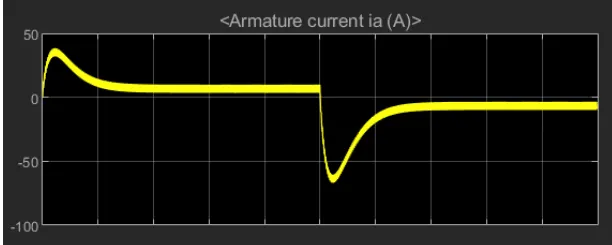
from armature current graph , we can see that ,at starting there is sudden spike increase in current at 0 sec also and at 0.5 sec also means at transition from positive to negative direction of rotation we observe a high surge in current, this is due to the transient switching occurring in the circuit.
As there is already current flowing in the circuit & on changing of switches after 0.5 sec, the current in the circuit adds to the changed direction of current and we observe a surge in current.
the surge in the current can be reduced by reducing the duty cycle.
in above results , the duty cycle selected as 75%.
by changing the duty cycle from 75% to 50% , the current surge can be reduced tremendously.
COMPARISON OF 4 QUADRANT CHOPPER AND BJT H BRIDGE:
1) the 4 quadrant chopper works in all four modes like
forward motoring
forward breaking
reverse motoring
reverse breaking
but the BJT h bridge model works on only two modes
forward motoring
reverse motoring
2)to change the direction of rotation of motor from forward to reverse and vice versa , the current signals get transited from one to other switch while in h bridge model, the direction of rotation of motor is changed by changing the polarity of current.
3)the 4 quadrant chopper have high switching frequency
while h bridge model have low switching frequency
4)the armature current in 4 quadrant chopper have a little spike at transition from one to other switch because of high swithing frequency while h bridge model have high spike of current.
5) the 4 quadrant chopper is generally used in industrial application while h bridge model is used in robotics.
TWO QUADRANT CHOPPER MODEL USING SIMULINK:
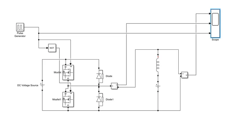
let us take two mosfet blocks and diodes blocks and connect it as shown in circuit diagram.
the dc voltage source is connected as shown.
let the voltage of dc voltage source be 24 volts.
let us consider an series RLC branch block and select inductor L . thus block works as a load.
to consider LE load ie motor load , and dc voltage source of 12 volt is also connected in series with inductor.
The pulse generator block is used to create gate pulse.
the not gate is used in the model so that the two mosfet will not get closed at the same time otherwise short circuit will occur .due to use of not gate , when one mosfet is ON the other mosfet will get off and when other mosfet is ON the first mosfet will get off .
The amplitude of pulse generator is kept 10 so that we can clearly see the pulses at scope and let period be 0.02 seconds and let pulse weidth be 50%
SCOPE RESULT:
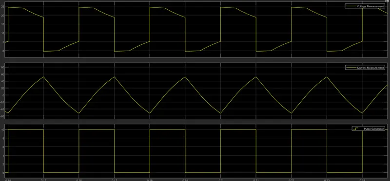
the voltage waveform is not going less than zero . the minimum value of voltage is zero and maximum value is always in the positive direction.
however in current waveform , the current increases and decreases. the current may be positive as well as negative.
and the pulse amplitude is 10 thus from pulse waveform we can see that the pulse amplitude is 10.
Brushless DC electric motors also known as electronically commutated motors .
A brushless DC motor (known as BLDC) is a permanent magnet synchronous electric motor which is driven by direct current (DC) electricity and it accomplishes electronically controlled commutation system (commutation is the process of producing rotational torque in the motor by changing phase currents through it at appropriate times) instead of a mechanically commutation system. BLDC motors are also referred as trapezoidal permanent magnet motors.
Unlike conventional brushed type DC motor, wherein the brushes make the mechanical contact with commutator on the rotor so as to form an electric path between a DC electric source and rotor armature windings, BLDC motor employs electrical commutation with permanent magnet rotor and a stator with a sequence of coils. In this motor, permanent magnet (or field poles) rotates and current carrying conductors are fixed.
stator
Stator of a BLDC motor made up of stacked steel laminations to carry the windings. These windings are placed in slots which are axially cut along the inner periphery of the stator. These windings can be arranged in either star or delta. However, most BLDC motors have three phase star connected stator.
Each winding is constructed with numerous interconnected coils, where one or more coils are placed in each slot. In order to form an even number of poles, each of these windings is distributed over the stator periphery.
Rotor
BLDC motor incorporates a permanent magnet in the rotor. The number of poles in the rotor can vary from 2 to 8 pole pairs with alternate south and north poles depending on the application requirement. In order to achieve maximum torque in the motor, the flux density of the material should be high. A proper magnetic material for the rotor is needed to produce required magnetic field density.