Week-7 Challenge: DC Motor Control
1.
A.
The speed control of a DC motor using BJT H-Bridge is the simulink model.It is used to generate a chopped voltage and to control the speed of a DC motor.An H-bridge is a simple circuit that let us to control a DC motor to go backward or forward.
In general an H-bridge is a rather simple circuit, containing four switching element, with the load at the center, in an H-like configuration:
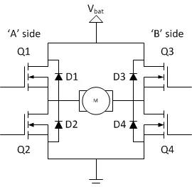
The switching elements (Q1..Q4) are usually bi-polar or FET transistors, in some high-voltage applications IGBTs. Integrated solutions also exist but whether the switching elements are integrated with their control circuits or not is not relevant for the most part for this discussion. The diodes (D1..D4) are called catch diodes and are usually of a Schottky type.The top-end of the bridge is connected to a power supply and the bottom-end is grounded.In general all four switching elements can be turned on and off independently, though there are some obvious restrictions.
Operation:
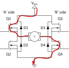
The basic operating mode of an H-bridge is fairly simple, if Q1 and Q4 are turned on, the left lead of the motor will be connected to the power supply, while the right lead is connected to ground. Current starts flowing through the motor which energizes the motor in the forward direction and the motor shaft starts spinning.
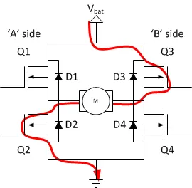
If Q2 and Q3 are turned on, the reverse will happen, the motor gets energized in the reverse direction, and the shaft will start spinning backwards.
In a bridge, you should never ever close both Q1 and Q2 (or Q3 and Q4) at the same time. If you did that, you just have created a really low-resistance path between power and GND, effectively short-circuiting your power supply. This condition is called ‘shoot-through’ and is an almost guaranteed way to quickly destroy your bridge, or something else inr circuit.
Model:
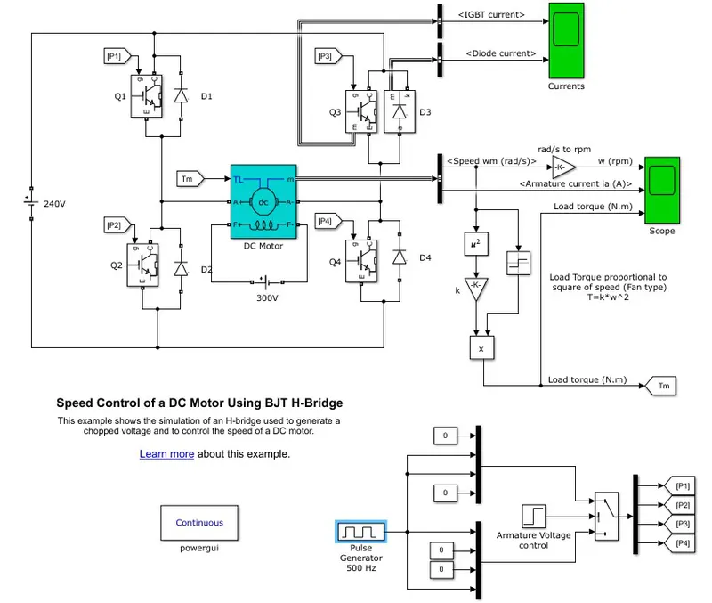
- Here H-bridge DC chopper circuit is designed to control the speed of the motor.
- IGBT acts as BJT in power switching devices.
- Four IGBT switches are used for inverting the DC voltage 0 to 240 v supply.The current flows from collector(C) to emitter(E).
- The gate are controlled by the pulses(0 and 1) according to the armature voltge of motor given by pulse generator.
- Here four switches are used Q1,Q2,Q3,Q4. Pulses P1,P2,P3,P4 are conected with corresponding switches.
- In first state, Q1 and Q4 are closed by giving 1V to IGBT'S,current from battery passes through Q1 and Q4.Diode D2,D3 are used as free wheeling diode in this state.In this case Forward motoring and forward breaking are held.
- In Second state,Q2 and Q3 are closed by giving 1V to IGBT's,current from battery passes through Q2 and Q3.Diode D1,D4 are used as free wheeling diode in this stateIn this case reverse motoring and reverse breaking are held.The current direction change its direction in this state.
- Both the states are occuring in 0.5 seconds in their sample time.Thus DC supply converted and feeded to the armature of the motor.
- Here free wheeling diodes are used as a safety purpose of this inverter circuit as when the flow of current on low values protects the circuit and machine by feed backing the current or in high voltage fluctuvations voltage get splited as protection to the motor and circuit components.
- In motor operation, armature terminals are connected with a 240V along the inverter circuit and field windings are connected with 300 V DC suppy to act as a electro magnet for the motor.
- The load torque is given as mechanical input to the motor for its referance.
- Thus through this magnetic fields generated, variable current carring conductors in rotor armature produces forces according to fleming left hand rule principle. Thus the motor starts to rotate.
Result:
B.
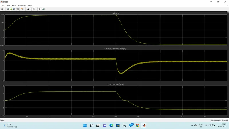
From armature current graph , we can see that ,at starting there is sudden spike increase in current at 0 sec also and at 0.5 sec also means at transition from positive to negative direction of rotation we observe a high surge in current, this is due to the transient switching occurring in the circuit.
As there is already current flowing in the circuit & on changing of switches after 0.5 sec, the current in the circuit adds to the changed direction of current and we observe a surge in current.
The surge in the current can be reduced by reducing the duty cycle.
By changing the duty cycle from 75% to 50% , the current surge can be reduced tremendously.
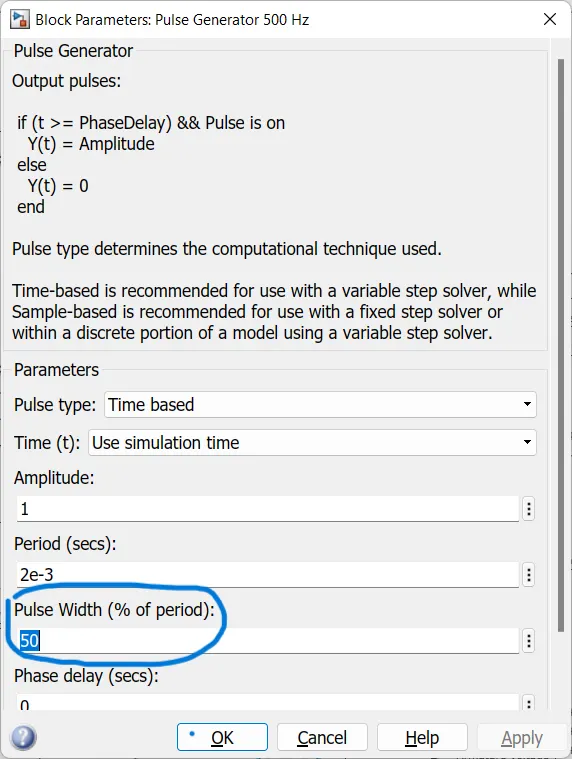
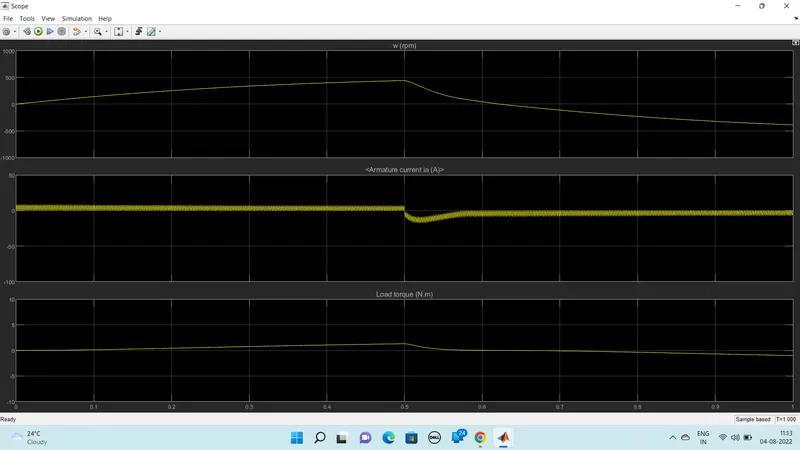
We can see from the output when the duty cycle is 50%. The armature current is lower as compared to the 75% duty cycle. Also, it can be observed that the IGBT Current and the Diode current are also lower when the duty cycle is 50% as in comparison with the 75% duty cycle.Thus we can find that , the armature curent spike is reduced by changing the duty cycle from 75% to 50%.
C.
Four-Quadrant Chopper DC Drive (DC7) block:
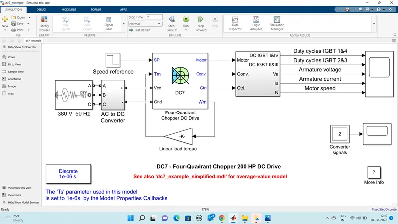
The Four-Quadrant Chopper DC Drive (DC7) block represents a four-quadrant, DC-supplied, chopper (or DC-DC PWM converter) drive for DC motors. This drive features closed-loop speed control with four-quadrant operation. The speed control loop outputs the reference armature current of the machine. Using a PI current controller, the chopper duty cycle corresponding to the commanded armature current is derived. This duty cycle is then compared with a sawtooth carrier signal to obtain the required PWM signals for the chopper.
The main advantage of this drive, compared with other DC drives, is that it can operate in all four quadrants (forward motoring, reverse regeneration, reverse motoring, and forward regeneration). In addition, due to the use of high switching frequency DC-DC converters, a lower armature current ripple (compared with thyristor-based DC drives) is obtained. However, four switching devices are required, which increases thecomplexity of the drive system.
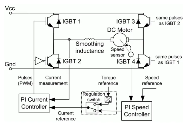
The machine is separately excited with a constant DC field voltage source. There is thus no field voltage control. By default, the field current is set to its steady-state value when a simulation is started.The armature voltage is provided by an IGBT converter controlled by two PI regulators. The converter is fed by a constant DC voltage source. Armature current oscillations are reduced by a smoothing inductance connected in series with the armature circuit.
Comparison of 4Quadrant Chopper DC Drive and BJT H-Bridge :
| 4-Quadrant Chopper DC Drive |
BJT H-Bridge |
|
|
2.
Two Quadrent CHopper
The Two – Quadrant Chopper block represents a 2 – quadrant-controlled chopper for converting a fixed DC input to a variable DC output. The block contains two switching devices.Class-C or Type-C Chopper is a category of chopper which can operate in first as well as second quadrant. This basically means that, the power can either flow from source to load or load to source in this chopper.
Operation of Two quadrent chopper:
As we know that, a Class A and Class B chopper operates in first and second quadrant respectively. Therefore, if we connect both these types of chopper in parallel then it is possible to have chopper operation in first as well as second quadrant. In fact, Class-C or Type-C chopper is obtained by the parallel connection of Class-A and Class-B chopper. Figure below shows the circuit diagram of this type of chopper.
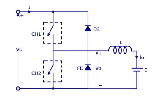
We can notice that chopper CH1, free-wheeling diode (FD) and load are forming Class-A Chopper whereas chopper CH2, D2 and Load are forming Class-B chopper. Both these choppers are connected in parallel. To obtain first quadrant operation we should switch ON chopper CH1 and for getting second quadrant operation we should switch ON chopper CH2. Let us discuss this in detail.
Case 1: When CH1 is switched ON/OFF
When chopper CH1 is switched ON, source Vs directly gets connected to the load and hence, load voltage Vo is equal to source voltage. The direction of load current is from source to load as shown in the circuit diagram which is assumed positive.
When CH1 is switched OFF, the free-wheeling diode FD comes into the circuit as it gets forward biased and hence shorts the load. Therefore, the output voltage Vo becomes zero. However, the io continues to die down through the FD and L in the same direction as shown in circuit diagram. Thus, the average output voltage Vo and current Io are positive and hence operation of chopper is in first quadrant.
Case 2: When CH2 is switched ON/OFF
When chopper CH2 is switched ON, load DC source E drives current through CH2 and load. The direction of this current io will be opposite to that shown in circuit diagram and hence is assumed negative. Output voltage Vo is zero during this time. When CH2 is made OFF, diode D2 gets forward biased and hence the current into the source from the load. The output voltage is Vs in this time as the load is connected to the source through D2 during OFF time of chopper CH2. Thus, the load current is always negative i.e. operation of chopper is within second quadrant.
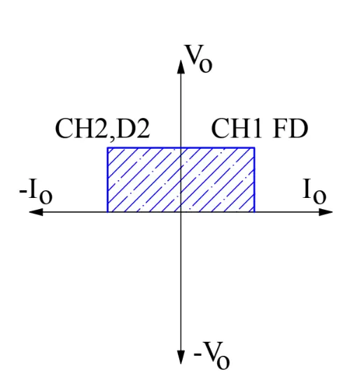
The average load voltage is always positive but the average load current may be positive or negative. Therefore, power flow may be from source to load (first quadrant operation) or load to source (second quadrant operation). The operating region of Class-C or Type-C chopper is shown below by hatched area.
Simulink model:
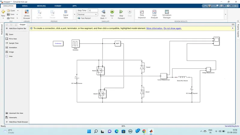
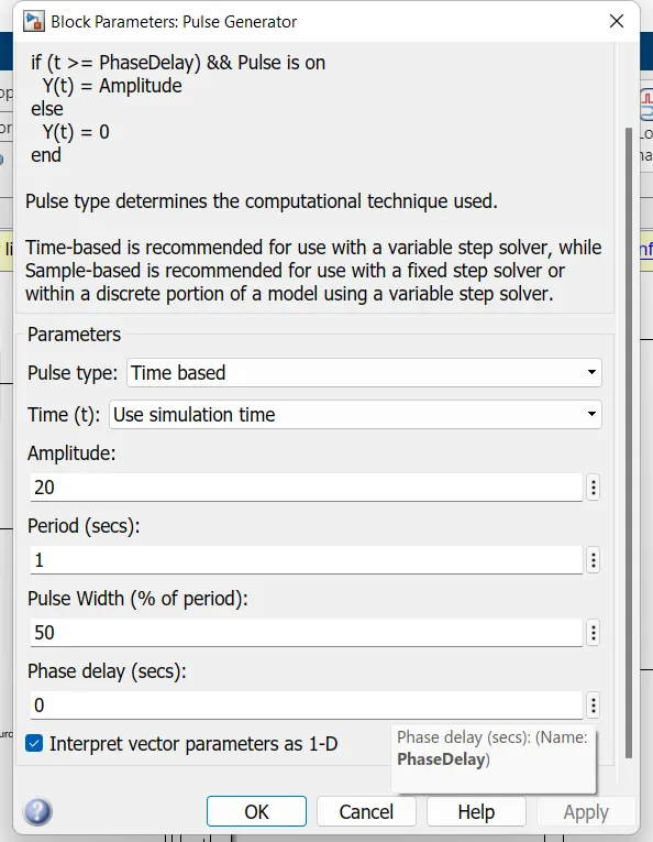
The pulse generator is used with the NOT gate to prevent misfiring of the MOSFETs so that they do not conduct at the same time which results in the short circuit.
 .
.
Source side voltage:
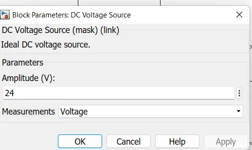
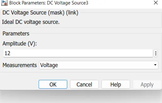
load side voltage:
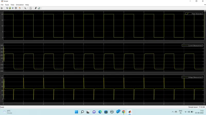
The voltage waveform is not going less than zero .The minimum value of voltage is zero and maximum value is always in the positive direction.However in current waveform , the current increases and decreases. the current may be positive as well as negative.So, the two quadrent chopper is simulated and verified.
Model is attached as a file.
3.
BLDC MOTOR
BLDC motor named as brushless dc motor having high effenciency than other types of motors.This motor is also known to be synchronous motor.Primary efficiency is a most importent feature for BLDC motors. Because the rotor is the sole bearer of the magnets and it doesn't require any power. i.e. no connections, no commutator and no brushes.
Construction of BLDC MOTOR:
In this motor, the permanent magnets attach to the rotor. The current-carrying conductors or armature windings are located on the stator. They use electrical commutation to convert electrical energy into mechanical energy.
The main design difference between a brushed and brushless motors is the replacement of mechanical commutator with an electric switch circuit. A BLDC Motor is a type of synchronous motor in the sense that the magnetic field generated by the stator and the rotor revolve at the same frequency.The controlling of motor is by changing the magnitude and direction of current flowing through the stator windings.
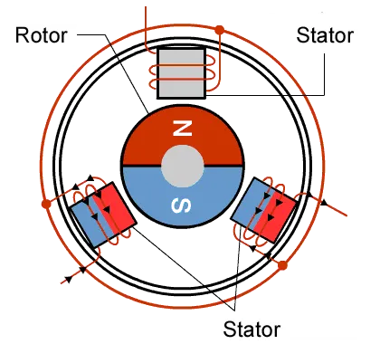
Brushless motor does not have any current carrying commutator. The field inside a brushless motor is switched through an amplifier which is triggered by the commutating device like an optical encoder.
A BLDC motor with three coils on the stator will have six electrical wires (two to each coil) extending from these coils. In most implementations three of these wires will be connected internally, with the three remaining wires extending from the motor body. Wiring in the BLDC motor case is more complicated than simply connecting the power cells positive and negative terminals. we will look more closely at how these motors work in the second session of this series.
Operations of BLDC motor:Brushed DC motor
BLDC motor works on the principle similar to that of a Brushed DC motor.The Lorentz force law which states that whenever a current carrying conductor placed in a magnetic field it experiences a force. As a consequence of reaction force, the magnet will experience an equal and opposite force. In the BLDC motor, the current carrying conductor is stationary and the permanent magnet is moving.
When the stator coils get a supply from source, it becomes electromagnet and starts producing the uniform field in the air gap. Though the source of supply is DC, switching makes to generate an AC voltage waveform with trapezoidal shape. Due to the force of interaction between electromagnet stator and permanent magnet rotor, the rotor continues to rotate.With the switching of windings as High and Low signals, corresponding winding energized as North and South poles. The permanent magnet rotor with North and South poles align with stator poles which causes the motor to rotate.
We can consider three winding terminal are comming out as U,V,W and their another ends are connected in single point as shown in below figure.The angle shift between two coils makes 120 degree.
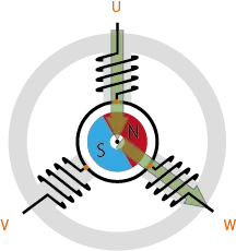
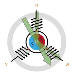
The current moves from U to W makes magnetizing the coils attracts the rotor consisting of permanent magnet makes moment as shown above to align with the resultant arrow(larger arrow).North pole of magnet towards arrow mark of resultant arrow.
Rotation is maintained by continually switching the flux so that the permanent magnet is constantly chasing the rotating magnetic field induced by the coils.In other words, energizing of U, V, and W must be continually switched so that the resultant flux keeps moving, producing a rotating field that continually pulls on the rotor magnet.
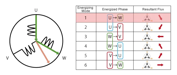
The above movement are acheived by continuous change in current direction over two poles of stator at single time.But this is slightly not continuous in their rotation.This makes motor vibration and noice will be produced.So, to attain smooth continuous rotation of rotor we have to control the current flow through all the three poles in same time.
As shown below we can acheive continuous change in current flow in all stator poles at same time in 120 degree phase shift.
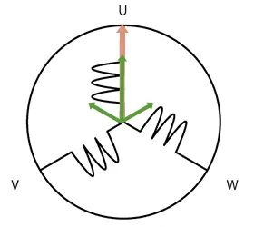
As we have seen, we drive BLDC motors by continually changing the directionality of the flux produced by the coils. The permanent magnets on the rotor continually chase the shifting rotating magnetic field,causing the rotor to turn.
Controlling of BLDC MOTOR:
By using the inverter circuitry to also adjust the voltage into each coil, we can control the magnitude of the current.A typical way to adjust the voltage is with pulse width modulation (PWM). We alter the voltage by lengthening or reducing the pulse ON time ( “Duty cycle”: the ON time expressed as a ratio of the ON+OFF switching interval). Increasing the duty cycle has the same effect as raising the voltage,reducing the duty cycle has the same effect as lowering the current.
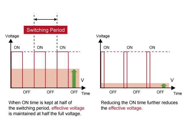
This is the working of BLDC motor.
References: