Week-7 Challenge: DC Motor Control
Week-7 Challenge: DC Motor Control
- Run MATLAB demo ‘Speed control of a DC motor using BJT H-bridge’. Modify the model such that armature current doesn’t shoot up when motor changes direction from forward to reverse.
- Refer to help section of ‘The Four-Quadrant Chopper DC Drive (DC7) block’. Compare it with H-bridge model.
- Make a suitable EV model using DC7 block and make result report.
Working Principle of BJT H-Bridge
- An H-bridge is a simple circuit that lets you control a DC motor to go backward or forward.
- You normally use it with a microcontroller, such as an Arduino, to control motors.
- When you can control two motors to go either forward or backward – you can build yourself a robot!
Here’s the concept of the H-bridge:
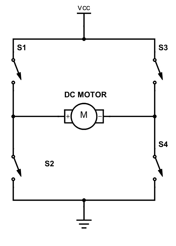
A DC motor spins either backward or forward, depending on how you connect the plus and the minus.
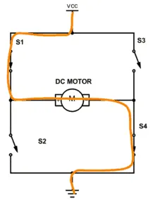
If you close switch 1 and 4, you have plus connected to the left side of the motor and minus to the other side. And the motor will start spinning in one direction
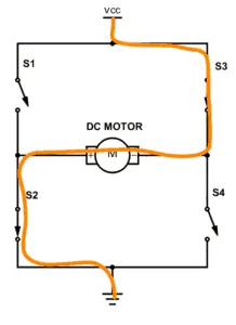
If you instead close switch 2 and 3, you have plus connected to the right side and minus to the left side. And the motor spins in the opposite direction.
- We can access the model of 'Speed control of a DC motor using BJT H-bridge' in help section of matlab.
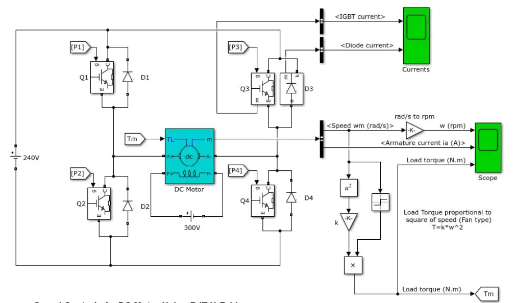
Fig- Above fig shows Speed control model of a DC motor using BJT H-bridge
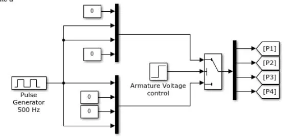
Fig- Above fig shows model used to give on off signals to BJT
- The Bipolar Junction Transistor (BJT) when used for power switching applications, operates as an IGBT. When it is conducting (BJT operating in the saturated region), a forward voltage Vf is developed between collector and emitter (in the range of 1 V). Therefore, the IGBT block can be used to model the BJT device.
- The IGBT block does not simulate the gate current controlling the BJT or IGBT. The switch is controlled by a Simulink® signal (1/0). The DC motor uses the pre-set model (5 HP 24V 1750 rpm). It simulates a fan type load (where Load torque is proportional to square of speed). The armature mean voltage can be varied from 0 to 240 V when the duty cycle (specified in the Pulse Generator block) is varied from 0 to 100%.
- The H-bridge consists of four BJT/Diode pairs (BJT simulated by IGBT models). Two transistors are switched simultaneously: Q1 and Q4 or Q2 and Q3. When Q1 and Q4 are fired, a positive voltage is applied to the motor and diodes D2-D3 operate as free-wheeling diodes when Q1 and Q4 are switched off. When Q2 and Q3 are fired, a negative voltage is applied to the motor and diodes D1-D4 operate as free-wheeling diodes when Q2 and Q3 are switched off.
BJT-
BJT is the short form of Bipolar Junction Transistor, it is a solid-state current-controlled device which can be used to electronically switch a circuit, you can think of it as your normal Fan or Light switch, but instead of you turning it on manually it can be controlled electronically. Technically speaking, BJT is a three-terminal device with an Emitter, collector, and a base pin, the current flow through the emitter and collector are controlled by the amount of current applied to the base.
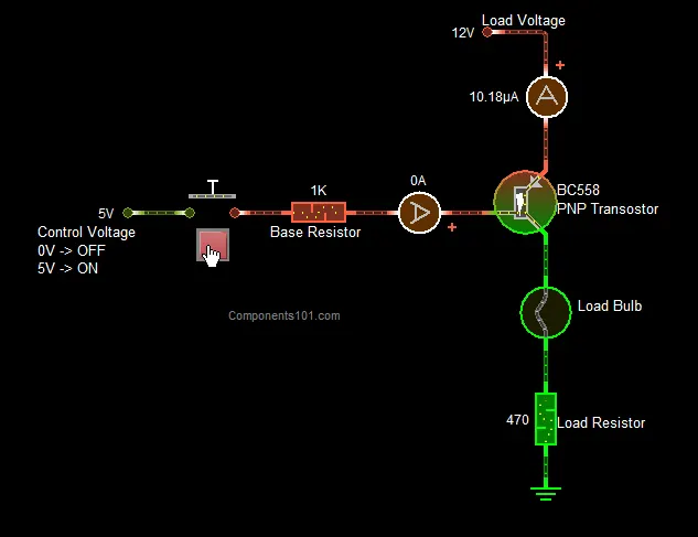
Fig- Above fig shows working of BJT transistors
There are two types of BJT transistors-
1) PNP transistors & 2) NPN transistors
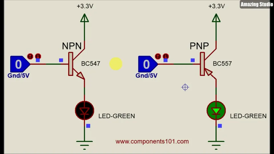
Fig- Above fig shows working of PNP & NPN transistor
The difference between the PNP and NPN transistors is that the arrow mark at the emitter end if you have noticed, the arrow in the PNP transistors is mentioned as moving from the emitter to the base whereas in the NPN transistors the arrow will be moving from the base to the emitter. The Direction of the arrow represents the direction of current flow in the transistor, in PNP the current will be flowing from emitter to base, similarly in the NPN transistor current will be flowing from the base to emitter.
- Run MATLAB demo ‘Speed control of a DC motor using BJT H-bridge’. Modify the model such that armature current doesn’t shoot up when motor changes direction from forward to reverse.
- First we have to check what parameters are set into pulse generator.
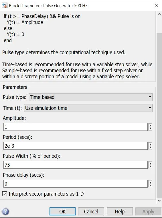
- We can see that here duty cycle is set to 75%. First we will take trial at default value.
-
Trail 1-
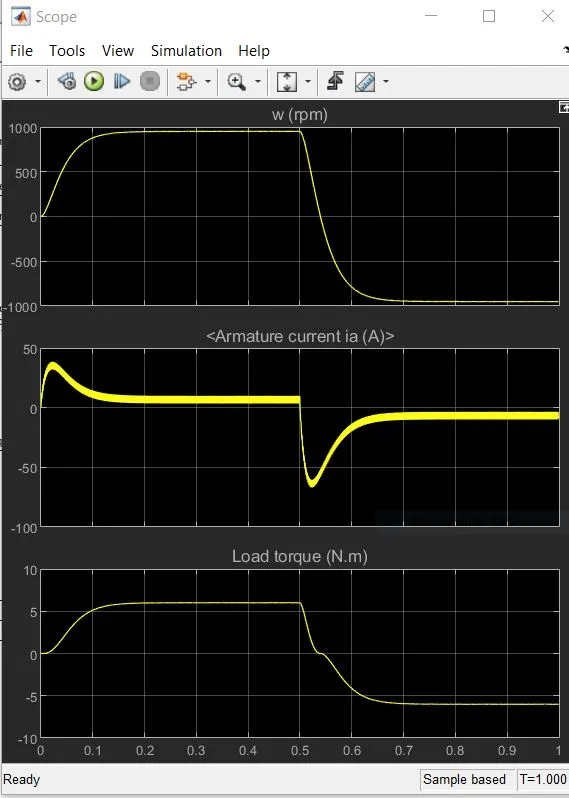
- In above graph it can be seen that armature current is getting shot up suddenly after t= 0.5sec
Trial 2-
- Now we will change the pulse width to 50% in pulse generator and will run the model again.
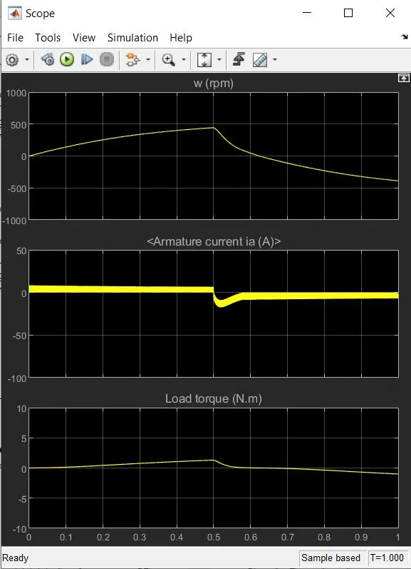
- In above graph it can be seen that armature current is still getting shot up but it is less than earlier.
Trial 3-
- Now we will change the pulse width to 45% in pulse generator and will run the model again.
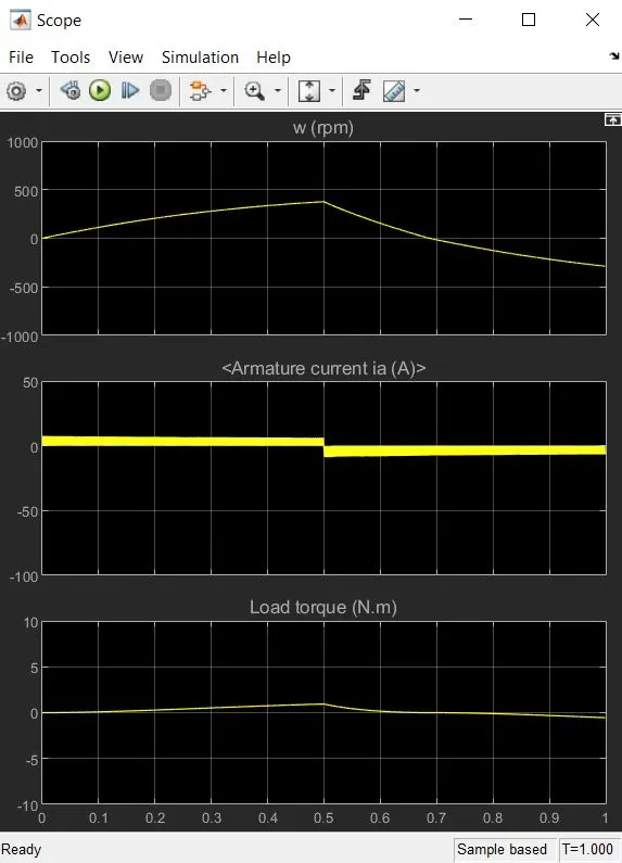
- In above graph it can be seen at duty cycle of 45% armature current doesn’t shoot up. It changes its value from +7A to -7A after 0.5sec.
- Compare the Four-Quadrant Chopper DC Drive (DC7) block with H-bridge model.
The Four-Quadrant Chopper DC Drive (DC7) block represents a four-quadrant, DC-supplied, chopper (or DC-DC PWM converter) drive for DC motors. This drive features closed-loop speed control with four-quadrant operation. The speed control loop outputs the reference armature current of the machine. Using a PI current controller, the chopper duty cycle corresponding to the commanded armature current is derived. This duty cycle is then compared with a saw tooth carrier signal to obtain the required PWM signals for the chopper.
The main advantage of this drive, compared with other DC drives, is that it can operate in all four quadrants (forward motoring, reverse regeneration, reverse motoring, and forward regeneration). In addition, due to the use of high switching frequency DC-DC converters, a lower armature current ripple (compared with thyristor-based DC drives) is obtained. However, four switching devices are required, which increases the complexity of the drive system.
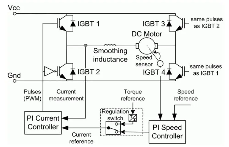
The machine is separately excited with a constant DC field voltage source. There is thus no field voltage control. By default, the field current is set to its steady-state value when a simulation is started.
The armature voltage is provided by an IGBT converter controlled by two PI regulators. The converter is fed by a constant DC voltage source. Armature current oscillations are reduced by a smoothing inductance connected in series with the armature circuit.
Working of DC7 block
(i) Quadrant I: In the first quadrant, the voltage and current are positive making the power is positive. In this case, the power flows from source to load. In this operation IGBT1 is ON, IGBT2 is OFF, IGBT4 is continuously ON and IGBT3 is continuously OFF. IGBT1 and IGBT4 are conducting in this mode.
(ii) Quadrant 2: In the second quadrant, the voltage is still positive but the current is negative. Therefore, the power is negative. In this case, the power flows from load to source and this can happen if the load is inductive or back emf source such as a dc motor .Here IGBT1 is OFF, IGBT2 is ON, IGBT4 is continuously ON and IGBT3 is continuously OFF. As the inductor current cannot be changed instantaneously.
(iii) Quadrant 3: In the third quadrant both the voltage and current are negative but the power is positive. In this case, the power flows from source to load. In this operation IGBT3 is ON, IGBT4 is OFF, IGBT2 is continuously ON and IGBT1 is continuously OFF.
(iv) Quadrant 4: In the fourth quadrant voltage is negative but current is positive. The power is therefore negative. Here IGBT3 is OFF, IGBT4 is ON, IGBT2 is continuously ON and IGBT1 is
continuously OFF. As the inductor current cannot be changed instantaneously.
Advantages
- 4 quadrant choppers have more control over the deceleration of the motor and can more accurately brake the motor. This will make the deceleration smoother.
- It reduces the risk of current spikes (and possibly damage the motor and the controller) which can occur when the motor is made to brake while running at a high speed. So the controller life is generally longer with 4 quadrant choppers.
- 4 quadrant choppers are more efficient because lesser energy is wasted as heat and lesser current spikes occur which means lesser power dissipation. Finally,
- 4 quadrant chopper makes regenerative braking possible so that when the motor is made to brake, the kinetic energy of the rotor moving is transferred back as electrical energy which can then be used to charge a battery.
Comparison to H-Bridge
- H-Bridges like the 4 quadrant choppers are also capable of the braking operation without using air resistance or friction or physical brakes to bring the motor to rest. 4 quadrant DC choppers are more commonly used in automobiles whereas BJT H-bridges are commonly used in robotics and electro-mechanical devices.
- Unlike 4 quadrant DC choppers, BJT H-bridges are not capable of performing regenerative braking but they can perform dynamic braking. It is this difference that makes 4 quadrant DC choppers useful in hybrid and electric vehicles.
- In 4 quadrant DC choppers, the current signals are interrupted with one another to change the direction of rotation of the motor. This is done by a speed reference or a drive cycle from which the speed values are converted to current signals which interrupt one another to change the rotation of direction of the motor. However in BJT H-bridges, the polarity of the current is reversed (depending on the duty cycle) to change the direction of rotation of the motor.
- Also, the current signals in 4 quadrant DC choppers are chopped meaning that they are not continuous, they are discrete and so take less time for simulations. But in BJT H-bridges, the current values are not chopped, meaning that they are continuous and so take more time for simulations.
- Finally, in 4 quadrant DC choppers, a PI controller is used to control the speed and the current and in the H-bridge, this is not implemented.
- Make a suitable EV model using DC7 block and make result report.
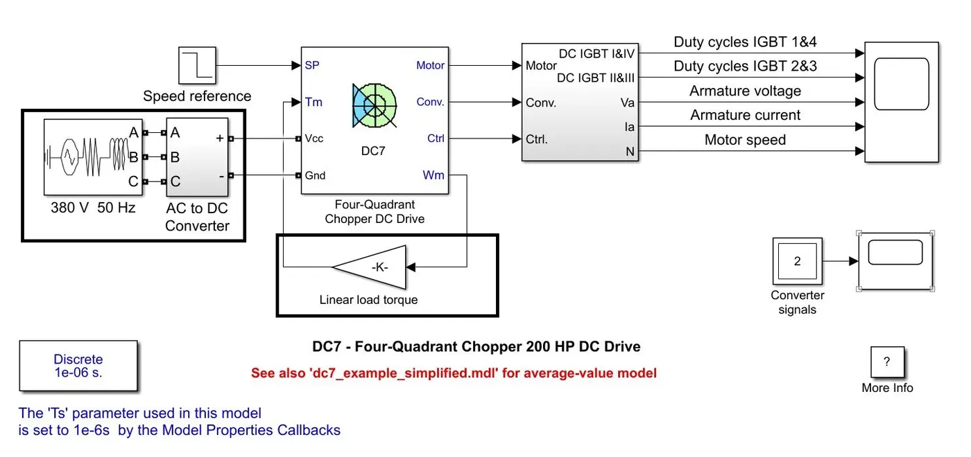
- In above model of DC7 we have to remove the higlighted blocks and add few blocks to create EV model.
- First we will remove linear load torque block and insert few blocks such that it will form a below torque equation
- `T_m = 0.0051omega^2 + 24.7`
where:
angular speed of motor (radians per second) - `omega`
Torque of motor (Nm) - Nm
- Math Function Block:
- We need to first insert the math function block which will perform power functions. In our case, we need to square the angular speed of the motor. So a connection is made between the DC chopper drive block to the math function block.
- Gain Block:
- Next, the math function block is connected to a 'gain' block to multiply the squared angular speeds with a coefficient, 0.0051 as needed by the torque-speed equation. The 'gain' block is modified with the gain value of 0.0051.
- Constant Block:
- A new block called a 'constant' block is created with a constant value of 24.7 as needed by the torque-speed equation.
- Add Block:
- The gain block and the constant block are separate and both connect to the 'add' block so that the terms from the 2 blocks are added together which gives the RHS of the torque-speed equation. The add block is then connected to the 'Tm' terminal of the DC chopper drive block.
Now we will add below blocks to provide source input.
- DC Voltage Block:
- Next, a DC voltage source block is inserted from the library and the negative terminal is connected to the 'Gnd' i.e. ground terminal of the DC chopper drive block. The DC voltage source is modifed with a voltage amplitude of 200V.
- Current Measurement Block:
-
The positive terminal of the DC voltage source is connected to a 'current measurement' block of which the negative terminal is connected to the 'Vcc' terminal of the DC chopper drive block.
- Scope Block:
- The 'i' terminal of the current measurement block is connected to a newly made 'scope' block.
- Manual Drive cycle block:
- A matrix of vehicle time & speed data is loaded and given as input to the DC7 chopper (SP terminal).
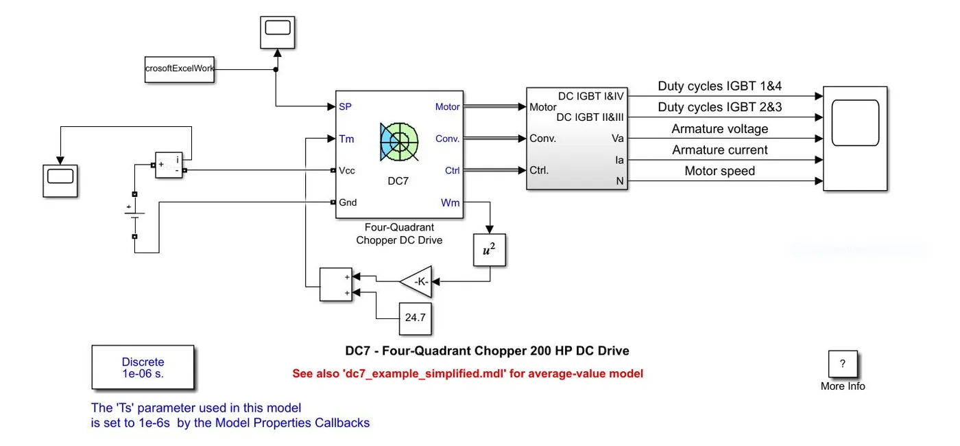
Fig - Above fig shows EV model using DC7 block
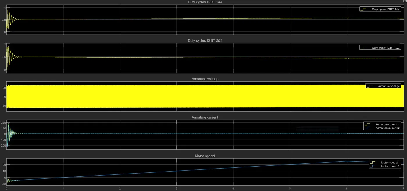
- Duty Cycles IGBT 1&4 and IGBT 2&3-
- From above output result it can be seen that at starting there is fluctuation is duty cycle in order to provide required voltage & current to motor.
- It gets stabilized as motor speed starts increasing.
- Duty cycle is directly proportional to the motor speed.
- Duty cycle of IGBT 1&2 and IGBT 2&3 are exactly opposite to each other.
- Armature voltage-
- Armature voltage fluctuates between 60 to -60V to provide the required power to motor.
- When IGBT 1&4 are ON we will get positive output voltage & when IGBT 2&3 is ON we will get negative voltage.
- Armature current-
- Initially there is fluctuation in current to provide starting power to motor but it gets stabilize.
- The maximum armature current and minimum armature current both decrease as the power requirement to the motor decreases when the motor angular speed decreases.
- Motor Speed:
- The angular speed of the motor increases gradually from rest at t = 0 seconds to a maximum level of 25 radians per second at t = 6 seconds. It is at this point, that the maximum power is required by the motor to achieve this angular speed. From here, the motor speed steadily decreases and returns to the resting state by the end of the drive cycle at t = 10 seconds.
Learning-
- Learned how to model EV using DC7 block.
- Learned Speed control of a DC motor using BJT H-bridge.
- Learned difference between DC7 block and H-bridge model.
Conclusion-
- Modifed the model such that armature current doesn’t shoot up when motor changes direction from forward to reverse.
- Made a EV model using DC7 block.