Week-7 Challenge: DC Motor Control
Aim: - To perform the below mentioned tasks:
- Run MATLAB demo ‘Speed control of a DC motor using BJT H-bridge’. Modify the model such that armature current doesn’t shoot up when motor changes direction from forward to reverse.
- Refer to help section of ‘The Four-Quadrant Chopper DC Drive (DC7) block’. Compare it with H-bridge model.
- Make a suitable EV model using DC7 block and make result report.
Study#1: -
Introduction to H-Bridge circuits-
In general an H-bridge is a rather simple circuit, containing four switching element, with the load at the centre, in an H-like configuration:
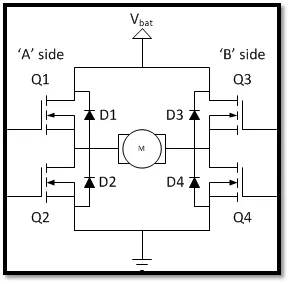
The switching elements (Q1 to Q4) are usually bi-polar or FET transistors, in some high-voltage applications IGBTs. The diodes (D1 to D4) are called catch diodes and are usually of a Schottky type. The top-end of the bridge is connected to a power supply (battery for example) and the bottom-end is grounded. In general all four switching elements can be turned on and off independently, though there are some obvious restrictions.
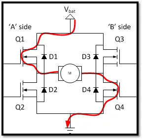
The basic operating mode of an H-bridge is fairly simple: if Q1 and Q4 are turned on, the left lead of the motor will be connected to the power supply, while the right lead is connected to ground. Current starts flowing through the motor which energizes the motor in the forward direction and the motor shaft starts spinning. This condition is called the forward motoring.
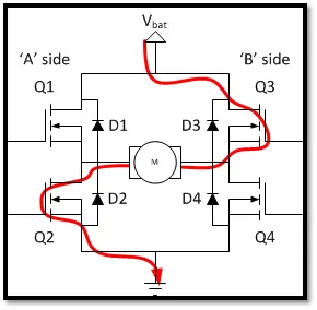
If Q2 and Q3 are turned on, the reverse will happen, the motor gets energized in the reverse direction, and the shaft will start spinning backwards. This condition is called the reverse motoring.
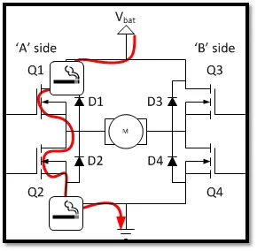
In a bridge, you should never ever close both Q1 and Q2 (or Q3 and Q4) at the same time. If you did that, you just have created a really low-resistance path between power and GND, effectively short-circuiting your power supply. This condition is called ‘shoot-through’ and is an almost guaranteed way to quickly destroy your bridge, or something else in your circuit.
Now we open the demo model ‘Speed control of a DC motor using BJT H-bridge’ in MATLAB.
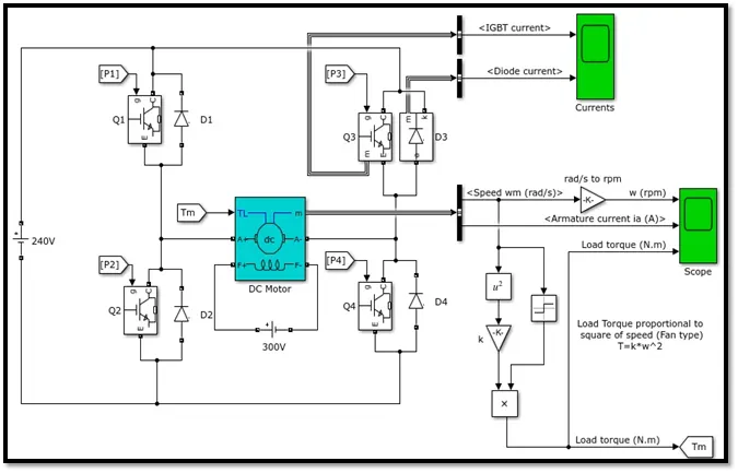
This model is an H-Bridge circuit and has the same working principle as explained above.
The output load in this model is a 5 HP DC motor with an angular velocity of 1750 rpm. The output motor voltage is controlled using duty cycle which is given as an input through a pulse generator. The armature mean voltage can be varied from 0 to 240 when duty cycle is varied from 0 to 100%.
Input Signal: -
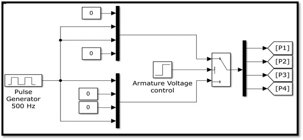
The pulse generator produces a signal as per the input parameters. The output from the pulse generator is armature voltage which is controlled via a control switch and then supplied into the H-Bridge circuit. The switches (Q1, Q2, Q3 and Q4) gets activated with respect to the input pulse received through the pulse generator. This drives the motor either in forward motoring condition or reverse motoring condition.
SIMULATON: -
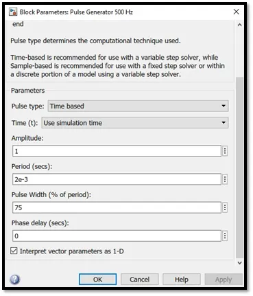
- Initially we run the Simulink model at its pre-set values (Duty Cycle = 75%) for a period of 1 second.
Pulse Generator input:
Output:
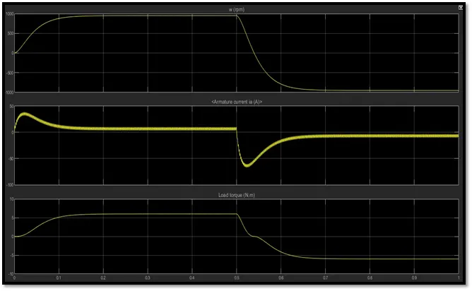
The following observation can be made from the above plot:
- The angular velocity of the motor increases up to 1000 rpm within 0.1 seconds and then it remains constant until half of the cycle and it falls down to a negative value (reverses the direction of rotation).
- Similarly in case of current, it spikes to a higher value at the beginning of cycle and then becomes steady for remaining half cycle. For the second half, its value becomes negative.
- There is a huge deflection in all the 3 values during transition of cycle which causes the most energy loss in the form of heat.
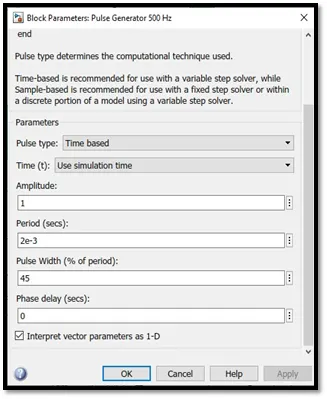
2. Changing the value of duty cycle (Duty Cycle = 45%) to reduce/neglect the losses:
Pulse Generator input:
Output:
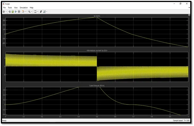
The following observation can be made from the above plot:
- The value of angular velocity of the motor has decreased to 300 rpm due to decrease in the voltage supply (caused due to reduction in duty cycle).
- By reducing the duty cycle to a sufficient value, the deflections during transition period has been reduced successfully.
Study#2: -
All types of DC-DC converters are capable of operating the motor operation in the first quadrant.
Power semiconductor devices (like SCR, MOSFET) used in chopper circuits are unidirectional devices. Some converters are capable of operating in two quadrants and some in all four quadrants.
Based on the number of quadrant a chopper can operate, the chopper circuits can be classified as follows:
- Single Quadrant Chopper:-
Example: Type-A Chopper, Type-B Chopper - Two quadrant Chopper:-
Example: Type-C Chopper, Type-D Chopper - Four quadrant Chopper;-
Example: Type-E Chopper
Four Quadrant Operation of Motor:
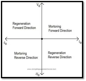
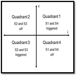
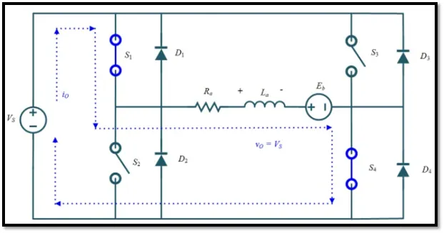
First Quadrant – Forward motoring mode: For first quadrant operation, thyristor S4 is kept on, thyristor S3 is kept off and thyristor switch S1 is operated. With S1, S4 ON, armature voltage Va = Vs and armature control Ia begins flow. Here both Va and Ia are positive giving first quadrant operation, when S1 is turned off, positive current freewheels through S4, D2. In this manner, Va, Ia can be controlled in this first quadrant, and operation gives forward motoring mode.
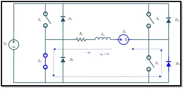
Second Quadrant – Forward braking mode: Here thyristor S2 is operated and S1 , S3 and S4 are kept off. With S4 on, reverse or negative current flows through La, S2, D4 and Eb. During the operation time of S2, the armature inductance ‘La’ stores energy during the time S2 is on. When S2 is turned off, current is fed back to source through diodes D1 , D4 . Note that here ( E+L(di/dt)) is more than the source voltage Vs .As the Vs is positive and Ia is negative, it is a second quadrant operation gives forward braking mode. In that power is fed back from armature to source.
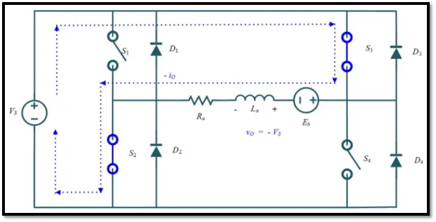
Third Quadrant – Reverse motoring mode: For third quadrant operation, thyristor S1 is kept off, S2 is kept on and S3 is operated, polarity of armature back emf Eb must be reversed for this quadrant operation. With thyristor S3 is on, armature gets connected to source V. so that both Va , Ia are negative, leading to third quadrant operation. When S3 is turned off,negative current free wheels through S2,D4. In this manner only Va and Ia can be controlled in the third quadrant.
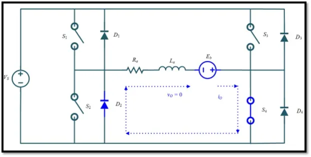
Fourth Quadrant – Reverse Braking mode: Here thyristor S4 is operated and other devices kept off, back emf Eb must have its polarity reversed as in third quadrant operation. With S4 on, positive current flows through S4,D2,La and Eb (armature). Armature inductance La stores energy during the time S4 is on. When S4 is turned off, current is fed back to source through diodes D2, D3.Here armature voltage Va is negative, but Ia is positive, leading to the chopper drive operation in the fourth quadrant. Also power is fed back from armature to source.
Simulink model for DC7 drive:
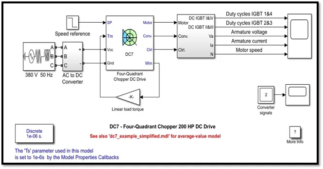
Description:
The 200 HP DC motor is separately excited with a constant 150 V DC field voltage source. The armature voltage is provided by an IGBT converter controlled by two PI regulators. The converter is fed by a 515 V DC bus obtained by rectification of a 380 V AC 50 Hz voltage source. In order to limit the DC bus voltage during dynamic braking mode, a braking chopper has been added between the diode rectifier and the DC7 block.
The first regulator is a speed regulator, followed by a current regulator. The speed regulator outputs the armature current reference (in p.u.) used by the current controller in order to obtain the electromagnetic torque needed to reach the desired speed. The speed reference change rate follows acceleration and deceleration ramps in order to avoid sudden reference changes that could cause armature over-current and destabilize the system. The current regulator controls the armature current by computing the appropriate duty ratios of the 5 kHz pulses of the four IGBT devices (Pulse Width Modulation). For proper system behaviour, the instantaneous pulse values of IGBT devices 1 and 4 are opposite to those of IGBT devices 2 and 3. This generates the average armature voltage needed to obtain the desired armature current. In order to limit the amplitude of the current oscillations, a smoothing inductance is placed in series with the armature circuit.
Comparison between Four-Quadrant Chopper DC Drive and H-bridge model:
|
Sr. No |
Four-Quadrant Chopper DC Drive |
H-bridge model |
|
1 |
Regenerative braking is possible |
Regenerative braking is not possible |
|
2 |
Current signals are interrupted with one another to change the direction of rotation of motor. |
The direction of current is reversed to change the direction of rotation of motor. |
|
3 |
PI controller is used to control the speed and current in the motor. |
PI controller is not used in this case. |
|
4 |
Since regenerative braking is possible, they have application in hybrid and pure electric vehicles. |
These find applications in robotics and electronic devices. |
References:
http://eeedrmcet.zohosites.com/files/Lecture%2016%204%20quadrant%20operation%20of%20chopper.pdf
https://electricalworkbook.com/four-quadrant-chopper-type-e-class-e/
http://www.completepowerelectronics.com/four-quadrant-operation-of-motor/
Study#3: -
Now we have created our EV model using the DC7 4-quadrant chopper Simulink model
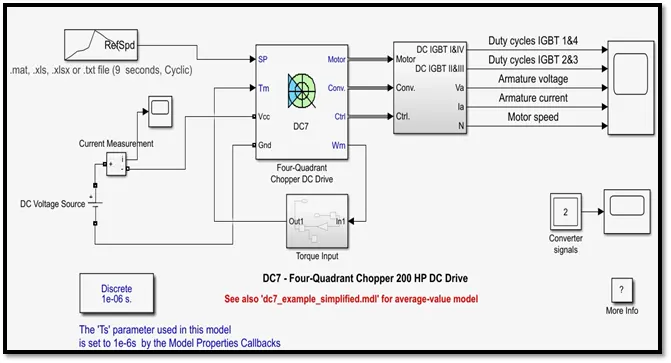
We have made some modifications in the default model such as:
Drive Cycle:
We have imported a custom made drive cycle (in Excel format). The drive cycle has a sample period of 9 seconds. It is connected to port 1 of the DC7 block.
DC Voltage Source:
A 100V Dc supply is provided here. It has a positive and negative end which are connected to the current measurement block and DC7 block respectively.
Current measurement:
This block has 3 terminals. The positive and negative end are connected to DC source and the motor respectively. The 3rd terminal is connected to a scope to visualize the input signal.
Torque Input subsystem:
The equation executed in this block is:

It represents the relation between the torque and speed of the motor.
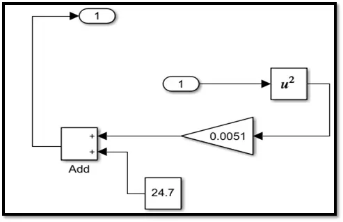
This block is responsible for the torque-speed relationship of the motor.
Output:
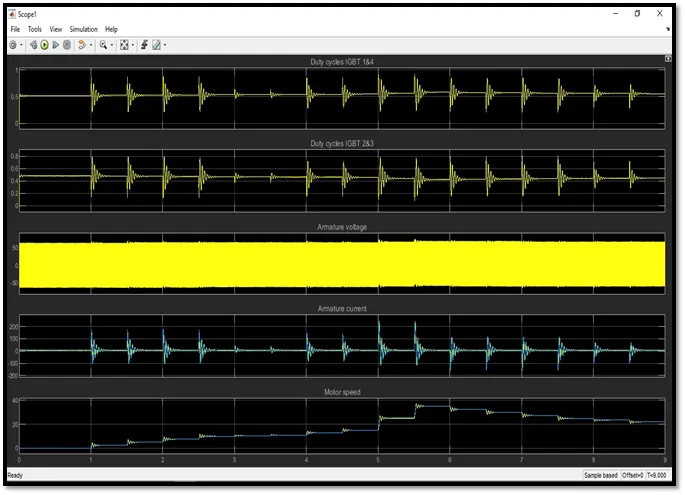
The following points can be concluded from the above output plot:
- The total sample time of the plot matches with the input sample time of 9 seconds.
- The armature voltage fluctuates between negative 50 and positive 50 which gives a total of 100 Volts (Supplied).
- The Duty Cycle IGBT 1&4 operates in the positive cycle while Duty Cycle IGBT 2&3 operates in the negative cycle.
- The small spikes in the graph represent the transition period between 2 halves of the cycle.
- The duty cycle is maximum when the required motor speed is maximum and its minimum when required motor speed is low. Varying the duty cycle controls the output voltage which in turn provides the desired motor speed.