Week-7 Challenge: DC Motor Control
- Run MATLAB demo ‘Speed control of a DC motor using BJT H-bridge’. Modify the model such that armature current doesn’t shoot up when motor changes direction from forward to reverse.
The BJT H-bridge Model of a DC motor
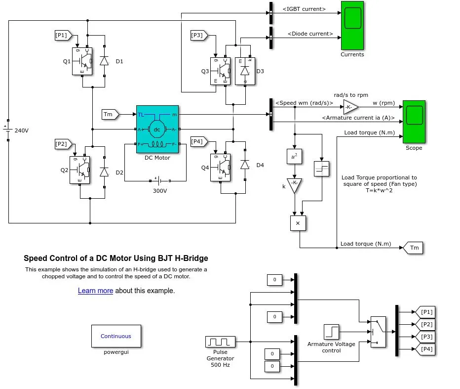
Description
The Bipolar Junction Transistor (BJT) when used for power switching applications, operates as an IGBT(insulated-gate bipolar transistor). An insulated-gate bipolar transistor (IGBT) is a three-terminal power semiconductor device primarily used as an electronic switch which, as it was developed, came to combine high efficiency and fast switching. When it is conducting (BJT operating in the saturated region), a forward voltage Vf is developed between collector and emitter (in the range of 1 V). Therefore, the IGBT block can be used to model the BJT device.
The IGBT block does not simulate the gate current controlling the BJT or IGBT. The switch is controlled by a Simulink® signal (1/0). The DC motor uses the preset model (5 HP 24V 1750 rpm). It simulates a fan type load (where Load torque is proportional to the square of speed). The armature mean voltage can be varied from 0 to 240 V when the duty cycle (specified in the Pulse Generator block) is varied from 0 to 100%.
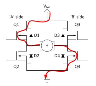
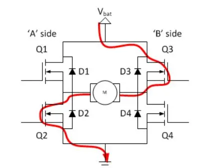
The H-bridge consists of four BJT/Diode pairs (BJT simulated by IGBT models). Two transistors are switched simultaneously: Q1 and Q4 or Q2 and Q3. When Q1 and Q4 are fired, a positive voltage is applied to the motor, and diodes D2-D3 operate as free-wheeling diodes when Q1 and Q4 are switched off. When Q2 and Q3 are fired, a negative voltage is applied to the motor and diodes D1-D4 operate as free-wheeling diodes when Q2 and Q3 are switched off.
Simulation
The motor starts in a positive direction with a duty cycle of 75% (mean DC voltage of 180V). At t= 0.5 sec., the armature voltage is suddenly reversed and the motor runs in a negative direction.
'Scope' shows motor speed, armature current, and load torque and 'Currents' shows currents flowing in BJT Q3 and diode D3.
The preset model used here is
5 HP 240 Volt 1750 RPM Field: 300Volt
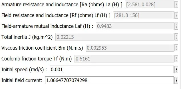
The Motor Parameter used in the model
When the simulation is run for the 1 second and click on the scope which shows the outcome from the armature current, torque and speed vs time.
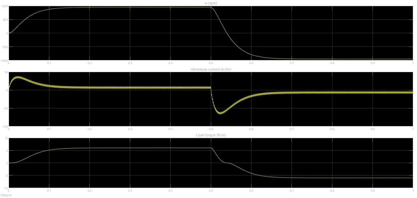
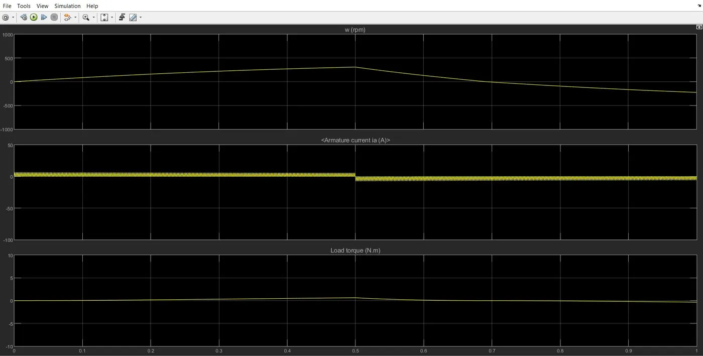
The above figure shows the when the speed is increasing the armature current is very high and it becomes constant after the speed is constant. The current changes the direction when the braking is applied and the torque is applied in the opposite direction.
`I = (V - E)/R ;`where V = rated voltage * duty cycle , E = back emf produced and R = armature resistance.
When speed is zero, the back emf is not produced and the resistance is very low therefore the current shows rise in its value. As the speed increases and it becomes stable, the back emf produced but less than the voltage therefore the current value gets stable. When the braking is applied the direction of the motor reversed the back emf value produced is higher than the applied voltage and the current produced in the opposite direction.
To reduce the spike in the current value in the reverse direction the difference between (V-E) should be reduced V can be reduced by reducing the duty cyle and the E may be reduced by reducing the speed of the motor.
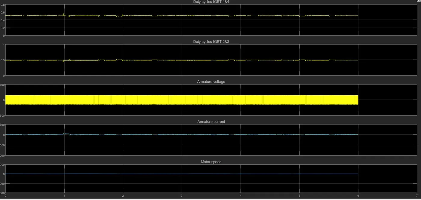
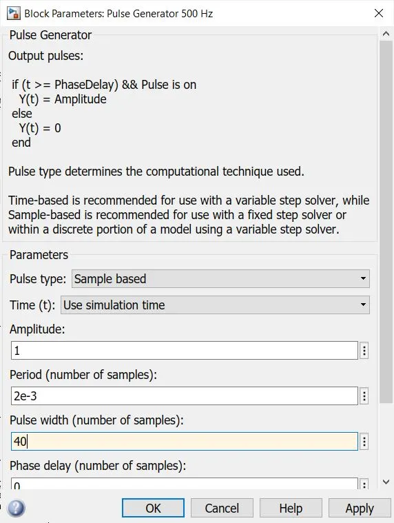
By changing the duty cycle from 75% to 45% the output will be shown like this
‘The Four-Quadrant Chopper DC Drive (DC7) block’. Compare it with H-bridge model.
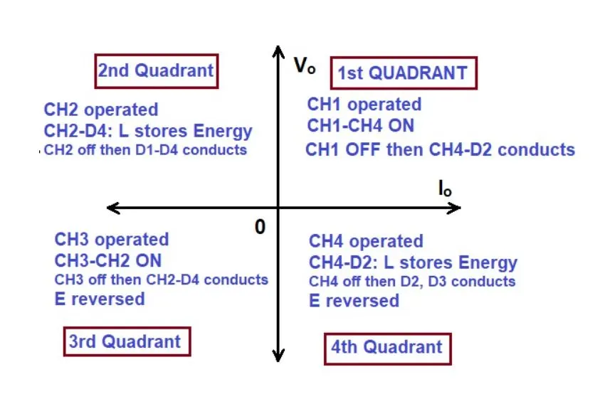
A four-quadrant chopper is a chopper that can be operated in all the four-quadrant. The power can flow either from source to load or load to source in this chopper. In the first quadrant, a Class-E chopper acts as a step-down chopper whereas in the second quadrant it behaves as a step-up chopper. This type of chopper is also known as Class-E or Type-E chopper.
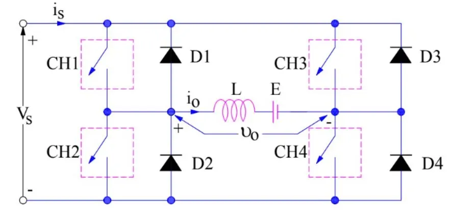
The circuit of a four quadrant chopper or class-E chopper basically consists of four semiconductor switches CH1 to CH4 and four diodes D1 to D4. The four diodes are connected in anti-parallel. The circuit diagram of this type of chopper is shown below.
An H-bridge is a simple circuit that lets you control a DC motor to go backward or forward. A DC motor spins either backward or forward, depending on how you connect the plus and the minus.
The basic operating mode of an H-bridge is fairly simple: if Q1 and Q4 are turned on, the left lead of the motor will be connected to the power supply, while the right lead is connected to ground. The current starts flowing through the motor which energizes the motor in the forward direction and the motor shaft starts spinning.
If Q2 and Q3 are turned on, the reverse will happen, the motor gets energized in the reverse direction, and the shaft will start spinning backward.
Make a suitable EV model using DC7 block
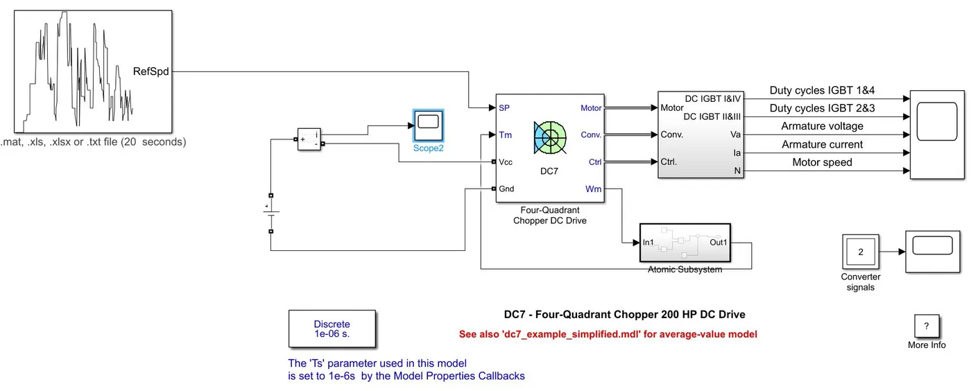
Using the DC7 example build a EV model.
Drive cycle
The drive cycle is used to plotting the data between speed and time in the excel sheet.
Modifying the Energy source:-
Using a dc source of 240 volt and attached a current measurement instrument with the battery. The scope is attached to the current measurement to record the output with the time
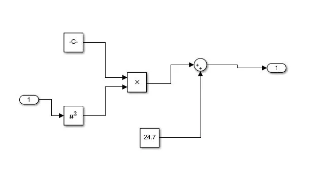
The torque relation is used by attaching a subsystem in the model
`T = 0.0051omega^2 + 0.27`
Results