Week-7 Challenge: DC Motor Control
Q.1
A. Explain a MATLAB demo model named ‘Speed control of a DC motor using BJT H-bridge’.
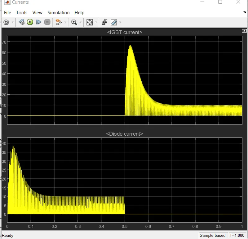
B. Comment on the armature current shoot-up from the scope results.
C. Refer to the help section of ‘The Four-Quadrant Chopper DC Drive (DC7) block’. Compare it with the H-bridge model.
Solution:
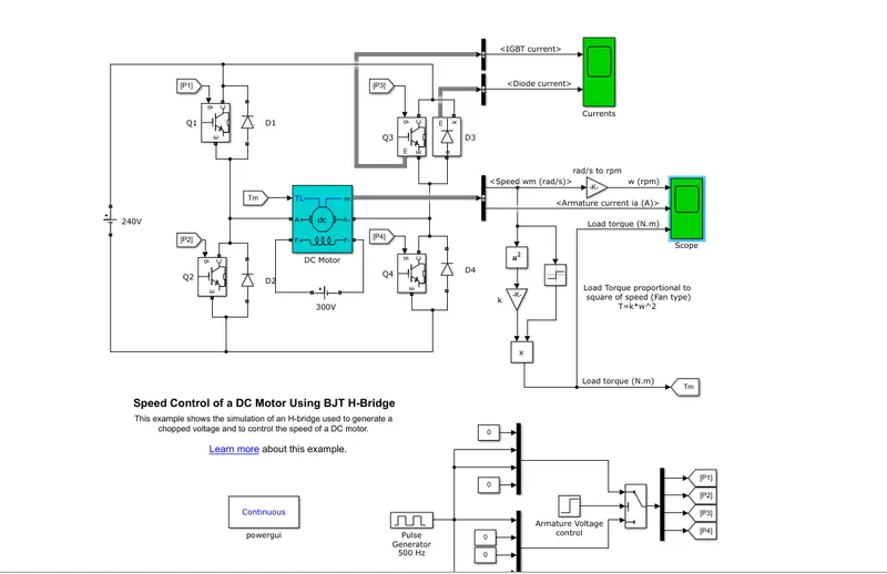
he Bipolar Junction Transistor (BJT) when used for power switching applications, operates as an IGBT. When it is conducting (BJT operating in the saturated region), a forward voltage Vf is developed between collector and emitter (in the range of 1 V). Therefore, the IGBT block can be used to model the BJT device.
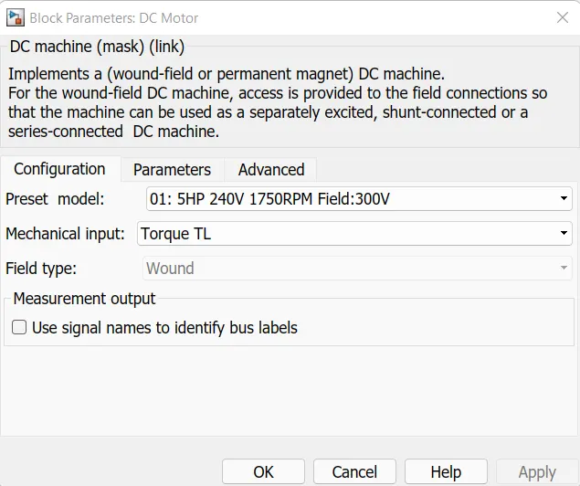
The IGBT block does not simulate the gate current controlling the BJT or IGBT. The switch is controlled by a Simulink® signal (1/0). The DC motor uses the preset model (5 HP 24V 1750 rpm). It simulates a fan type load (where Load torque is proportional to square of speed). The armature mean voltage can be varied from 0 to 240 V when the duty cycle (specified in the Pulse Generator block) is varied from 0 to 100%.
The H-bridge consists of four BJT/Diode pairs (BJT simulated by IGBT models). Two transistors are switched simultaneously: Q1 and Q4 or Q2 and Q3. When Q1 and Q4 are fired, a positive voltage is applied to the motor and diodes D2-D3 operate as free-wheeling diodes when Q1 and Q4 are switched off. When Q2 and Q3 are fired, a negative voltage is applied to the motor and diodes D1-D4 operate as free-wheeling diodes when Q2 and Q3 are switched off.
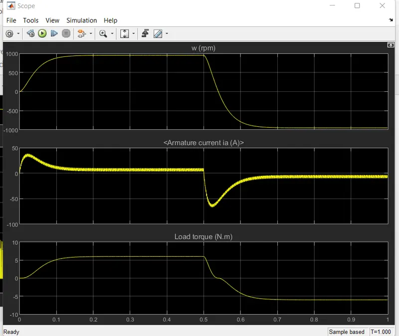
The motor starts in the positive direction with a duty cycle of 75% (mean DC voltage of 180V). At t= 0.5 sec., the armature voltage is suddenly reversed and the motor runs in the negative direction.
'Scope' shows motor speed, armature current and load torque and 'Currents' shows currents flowing in BJT Q3 and diode D3.
C. Refer to the help section of ‘The Four-Quadrant Chopper DC Drive (DC7) block’. Compare it with the H-bridge model.
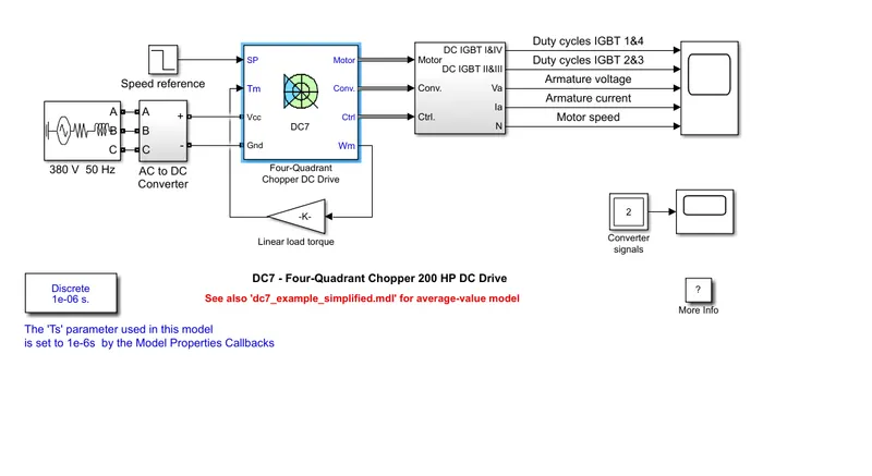
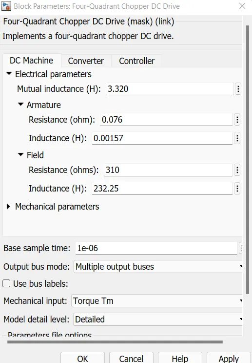
The 200 HP DC motor is separately excited with a constant 150 V DC field voltage source. The armature voltage is provided by an IGBT converter controlled by two PI regulators. The converter is fed by a 515 V DC bus obtained by rectification of a 380 V AC 50 Hz voltage source. In order to limit the DC bus voltage during dynamic braking mode, a braking chopper has been added between the diode rectifier and the DC7 block.
The first regulator is a speed regulator, followed by a current regulator. The speed regulator outputs the armature current reference (in p.u.) used by the current controller in order to obtain the electromagnetic torque needed to reach the desired speed. The speed reference change rate follows acceleration and deceleration ramps in order to avoid sudden reference changes that could cause armature over-current and destabilize the system. The current regulator controls the armature current by computing the appropriate duty ratios of the 5 kHz pulses of the four IGBT devices (Pulse Width Modulation). For proper system behaviour, the instantaneous pulse values of IGBT devices 1 and 4 are opposite to those of IGBT devices 2 and 3. This generates the average armature voltage needed to obtain the desired armature current. In order to limit the amplitude of the current oscillations, a smoothing inductance is placed in series with the armature circuit.
Simulation
Before starting the simulation, set the initial bus voltage to 515 V via the GUI block ('Initial States Setting' button and 'Cbus' variable).
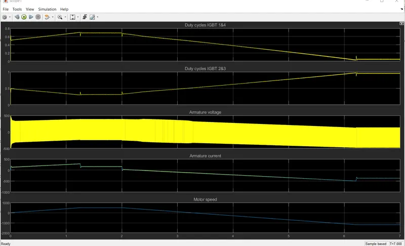
Start the simulation. You can observe the motor armature voltage and current, the four IGBT pulses and the motor speed on the scope. The current and speed references are also shown.
The motor is coupled to a linear load, which means that the mechanical torque of the load is proportional to the speed.
The speed reference is set at 500 rpm at t = 0 s. Observe that the motor speed follows the reference ramp accurately (+400 rpm/s) and reaches steady state around t = 1.3 s.
The armature current follows the current reference very well, with fast response time and small ripples. Notice that the current ripple frequency is 5 kHz.
At t = 2 s, speed reference drops to -1184 rpm. The current reference decreases to reduce the electromagnetic torque and causes the motor to decelerate with the help of the load torque.
At t = 2.2 s, the current reverses in order to produce a braking electromagnetic torque (dynamic braking mode). This causes the DC bus voltage to increase.
At t = 3.25 s, the motor reaches 0 rpm and the load torque reverses and becomes negative. The negative current now produces an accelerating electromagnetic torque to allow the motor to follow the negative speed ramp (-400 rpm/s). At t = 6.3 s, the speed reaches -1184 rpm and stabilizes around its reference.
Notes
1) The power system has been discretized with a 1 us time step. The speed and current controllers use a 100 us and 20 us sampling time respectively in order to simulate a microcontroller control device.
2) In order to reduce the number of points stored in the scope memory, a decimation factor of 25 is used. Some transitions may thus not appear on the scope. To view detailed simulation results, reduce the decimation factor to 1.
3) A simplified version of the model using an average-value converter can be used by selecting 'Average' in the 'Model detail level' menu of the graphical user-interface. The time step can then be increased up to the smallest control system sample time value. This can be done by typing 'Ts = 20e-6' in the workspace in the case of this example. See also dc7_example_simplified model.
Q.3Explain in a brief about operation of BLDC motor.
source of airtical https://www.renesas.com/us/en BLDC MOTOR
BLDC MOTOR:
What are Brushless DC Motors
Understanding the principle and application of high efficiency motors: 1 of 3
A motor converts supplied electrical energy into mechanical energy. Various types of motors are in common use. Among these, brushless DC motors (BLDC) feature high efficiency and excellent controllability, and are widely used in many applications. The BLDC motor has power-saving advantages relative to other motor types.
Motors are Power Delivery Machines
When engineers are faced with the challenge of designing electrical equipment to perform mechanical tasks, they might think about how electrical signals get converted to energy. So actuators and motors are among the devices that convert electrical signals into motion. Motors exchange electrical energy to mechanical energy.
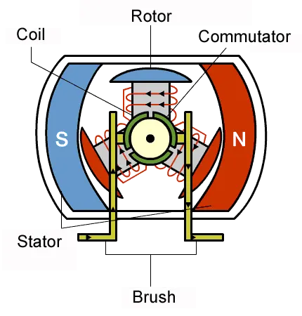
The simplest type of motor is the brushed DC motor. In this type of motor, electrical current is passed through coils that are arranged within a fixed magnetic field. The current generates magnetic fields in the coils; this causes the coil assembly to rotate, as each coil is pushed away from the like pole and pulled toward the unlike pole of the fixed field. To maintain rotation, it is necessary to continually reverse the current—so that coil polarities will continually flip, causing the coils to continue “chasing” the unlike fixed poles. Power to the coils is supplied through fixed conductive brushes that make contact with a rotating commutator; it is the rotation of the commutator that causes the reversal of the current through the coils. The commutator and brushes are the key components distinguishing the brushed DC motor from other motor types. Figure 1 illustrates the general principle of the brushed motor.
Common Motor Types
Motors differ according to their power type (AC or DC) and their method for generating rotation (Figure 2). Below, we look briefly at the features and uses of each type.
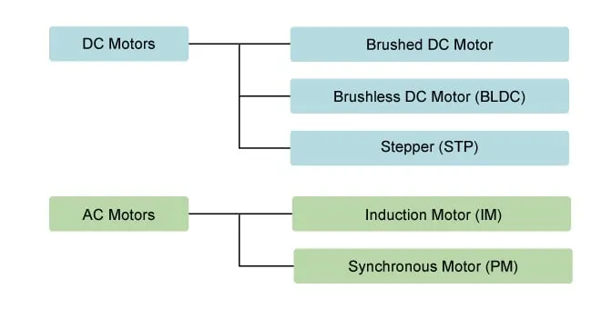
Figure 2: Different Types of Motors
Brushed DC motors, featuring simple design and easy control, are widely used to open and close disk trays. In cars, they are often used for retracting, extending, and positioning electrically-powered side windows. The low cost of these motors makes them suitable for many uses. One drawback, however, is that brushes and commutators tend to wear relatively quickly as a result of their continued contact, requiring frequent replacement and periodic maintenance.
A stepper motor is driven by pulses; it rotates through a specific angle (step) with each pulse. Because the rotation is precisely controlled by the number of pulses received, these motors are widely used to implement positional adjustments. They are often used, for example, to control paper feed in fax machines and printers—since these devices feed paper in fixed steps, which are easily correlated with pulse count. Pausing can also be easily controlled, as motor rotation stops instantly when the pulse signal is interrupted.
With synchronous motors, rotation is synchronous with the frequency of the supply current. These motors are often used to drive the rotating trays in microwave ovens; reduction gears in the motor unit can be used to obtain the appropriate rotational speeds to heat food. With induction motors, too, the rotation speed varies with frequency; but the movement is not synchronous. In the past, these motors were often used in electric fans and washing machines.
There are various types of motor in common use. In this session, we look at the advantages and applications of brushless DC motors.
Why Do BLDC Motors Turn?
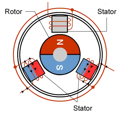
As their name implies, brushless DC motors do not use brushes. With brushed motors, the brushes deliver current through the commutator into the coils on the rotor. So how does a brushless motor pass current to the rotor coils? It doesn’t—because the coils are not located on the rotor. Instead, the rotor is a permanent magnet; the coils do not rotate, but are instead fixed in place on the stator. Because the coils do not move, there is no need for brushes and a commutator. (See Figure. 3.)
With the brushed motor, rotation is achieved by controlling the magnetic fields generated by the coils on the rotor, while the magnetic field generated by the stationary magnets remains fixed. To change the rotation speed, you change the voltage for the coils. With a BLDC motor, it is the permanent magnet that rotates; rotation is achieved by changing the direction of the magnetic fields generated by the surrounding stationary coils. To control the rotation, you adjust the magnitude and direction of the current into these coils.
Figure 3: A BLDC Motor.
Since the rotor is a permanent magnet, it needs no current, eliminating the need for brushes and commutator. Current to the fixed coils is controlled from the outside.
Advantages of BLDC Motors
A BLDC motor with three coils on the stator will have six electrical wires (two to each coil) extending from these coils. In most implementations three of these wires will be connected internally, with the three remaining wires extending from the motor body (in contrast to the two wires extending from the brushed motor described earlier). Wiring in the BLDC motor case is more complicated than simply connecting the power cell’s positive and negative terminals; we will look more closely at how these motors work in the second session of this series. Below, we conclude by looking at the advantages of by BLDC motors.
One big advantage is efficiency, as these motors can control continuously at maximum rotational force (torque). Brushed motors, in contrast, reach maximum torque at only certain points in the rotation. For a brushed motor to deliver the same torque as a brushless model, it would need to use larger magnets. This is why even small BLDC motors can deliver considerable power.
The second big advantage—related to the first—is controllability. BLDC motors can be controlled, using feedback mechanisms, to delivery precisely the desired torque and rotation speed. Precision control in turn reduces energy consumption and heat generation, and—in cases where motors are battery powered—lengthens the battery life.
BLDC motors also offer high durability and low electric noise generation, thanks to the lack of brushes. With brushed motors, the brushes and commutator wear down as a result of continuous moving contact, and also produce sparks where contact is made. Electrical noise, in particular, is the result of the strong sparks that tend to occur at the areas where the brushes pass over the gaps in the commutator. This is why BLDC motors are often considered preferable in applications where it is important to avoid electrical noise.
Ideal Applications for BLDC Motors
We’ve seen that BLDC motors offer high efficiency and controllability, and that they have a long operating life. So what are they good for? Because of their efficiency and longevity, they are widely used in devices that run continuously. They have long been used in washing machines, air conditioners, and other consumer electronics; and more recently, they are appearing in fans, where their high efficiency has contributed to a significant reduction in power consumption.
They are also being used to drive vacuum machines. In one case, a change in the control program resulted in a large jump in rotational speed—an example of the superlative controllability offered by these motors.
BLDC motors are also being used to spin hard disc drives, where their durability keeps the drives operating dependably over the long term, while their power efficiency contributes to energy reduction in an area where this is becoming increasingly important.
Toward Wider Usage in the Future
We can expect to see BLDC motors used in a wider range of applications in the future. For example, they will probably be widely used to drive service robots—small robots that deliver services in fields other than manufacturing. One might think that stepper motors would be more suitable in this type of application, where pulses could be used to precisely control positioning. But BLDC motors are better suited to controlling the force. And with a stepper motor, holding the position of a structure such as a robot arm would require a relatively large and continuous current. With a BLDC motor, all that would be required is a current proportionate to the external force—allowing for more power-efficient control. BLDC motors may also be replacing simple brushed dc motors in golf carts and mobility carts. In addition to their better efficiency, BLDC motors can also deliver more precise control—which in turn can further extend battery life.
BLDC motors are also ideal for drones. Their ability to deliver precision control makes them especially suited for multirotor drones, where the drone’s attitude is controlled by precisely controlling the rotational speed of each rotor.
In this session, we have seen how BLDC motors offer excellent efficiency, controllability, and longevity. But careful and proper control is essential to taking full advantage of these motors’ potential. In our next session, we will look at how these motors work.
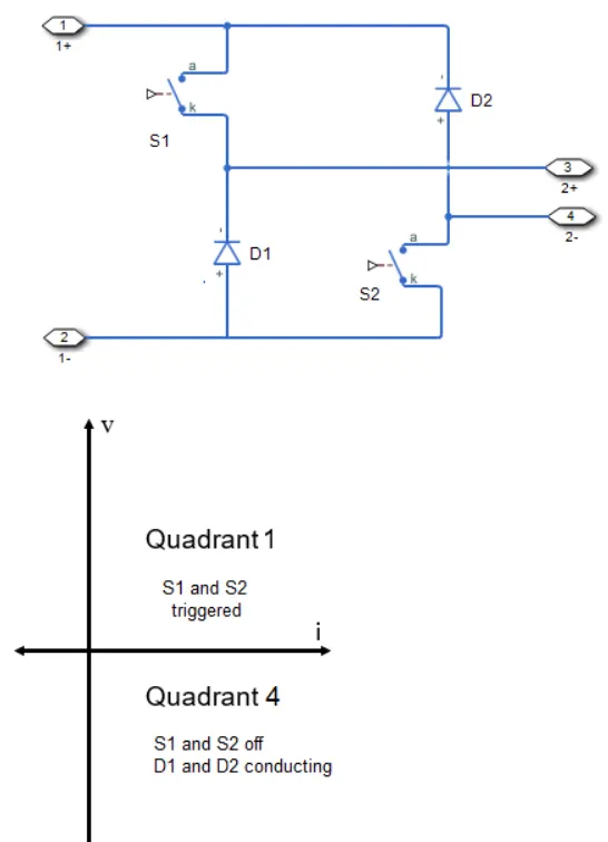
2. Develop a 2-quadrant chopper using simulink & explain the working of the same with the relevant results. (Refer to article - Multiquadrant operation of motor )
Solution:
Two Quadrant Chopper:
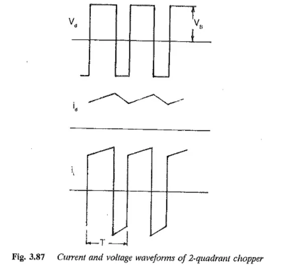
Sometimes a chopper may be required to provide a two quadrant operation by retaining the current direction in both motoring and braking modes. Such a Two Quadrant Chopper is shown in Fig. 3.86, and its waveforms in Fig. 3.87. The chopper permits a change in the polarity of terminal voltage keeping the direction of current constant. In Fig. 3.86 S1 and S2 are the choppers working as electronic switches and D1 and D2 are the feedback diodes. Assuming continuous conduction, both S1 and S2 operate simultaneously.
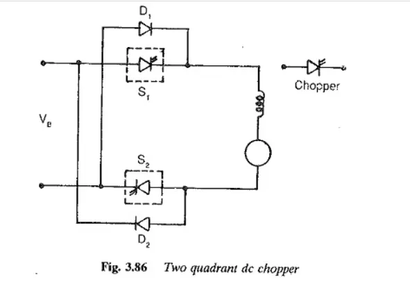
When they are ON, the load current Id increases, with the rate of rise depending upon the back emf and torque of the machine. When they are OFF, the load current is fed to the supply through the diodes D1 and D2. The current decreases in this stage. From Fig. 3.87, it is clear that the load voltage is effectively negative when the diodes conduct. The average value of the output voltage of the chopper
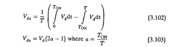
Vda is zero for a = 0.5, the output voltage is an ac waveform with average voltage equal to zero. For a > 0.5 the average value of the dc voltage is negative. The chopper works in the regeneration mode. The power flows from the load to the supply and the dc machine operates as a generator. For control ratios a c 0.5, the operation is similar to the inversion of a line commutated converter (α > 90°). For a > 0.5 the chopper has normal operation. The power flows from the supply to the load. This operation of the chopper is similar to rectification of a line commutated converter (α < 90°). For, a = 0.5 the load voltage is zero. The control characteristic of a two quadrant chopper is shown in Fig. 3.87.
MATLAB MODEL:
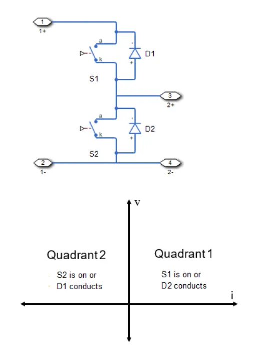
There are two model variants for the block. To access the model variants, in the model window, right-click the block. From the context menu, select Simscape > Block choices.
The model variants are:
-
First- and second- quadrant chopper. This block choice is the default. The figures show the equivalent circuit and the operation for the first- and second- quadrant model.
First- and fourth- quadrant chopper. The figures show the equivalent circuit and the operation for the first- and fourth- quadrant model.