Week-7 Challenge: DC Motor Control
1).Speed control of a DC motor using BJT H-Bridge:-
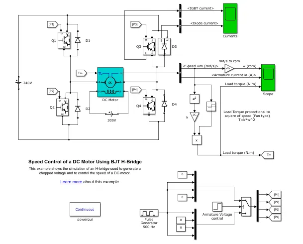
Here in the model four switches are used thus four pulse signals are generated accordingly.
(A) Working of H-bridge model:-
- Here H-bridge DC chopper circuit is designed to control the speed of the motor.
- IGBT acts as BJT in power switching devices.
- Four IGBT switches are used for inverting the DC voltage 0 to 240v supply. The current flows from collector to emitter.
- The gate are controlled by the pulses (0 and 1) according to the armature voltage of motor given by pulse generator.
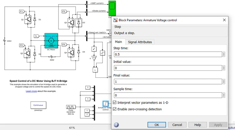
- This image shows the voltage value given from initial to final during the step time. According to the pulses on and off the voltage supplied to the IGBT's.
- Here four switches are used Q1,Q2,Q3,Q4. Pulses P1,P2,P3,P4 are connected with corresponding switches.
- In first state, Q1 and Q4 are closed by giving 1V to IGBT's current from batter passes through Q1 and Q4. Diode D2, D3 are used as free wheeling diode in this state. In this case Forward motoring and Forward breaking are held.
- In second state Q2 and Q3 are closed by giving 1V to IGBT's current from battery passes through Q2 and Q3. Diode D1,D4 are used as free wheeling diode in this state. In this case reverse motoring and reverse breaking are held. The current direction change its direction in this state.
- Both the states are occuring in 0.5 seconds in their sample time. Thus DC supply converted and feeded to the armature of the motor.
- Here free wheeling diodes are used as when the flow of current on low values protects the circuit and machine by feed backing the current or in high voltage fluctuations voltage get splited as protection to the motor and circuit components.
- In motor operation, armature terminals are connected with a 240V along the inverter circuit and field windings are connected with 300V DC supply to act as a electro magnet for the motor.
- The load torque is given as mechanical input to the motor for its reference.
- Thus through this magnetic fields generated, variable current carring conductors in rotor armature produces forces according to fleming left hand rule principle. Thus the motor starts to rotate.
- Here run this demo model and study the results from scopes.
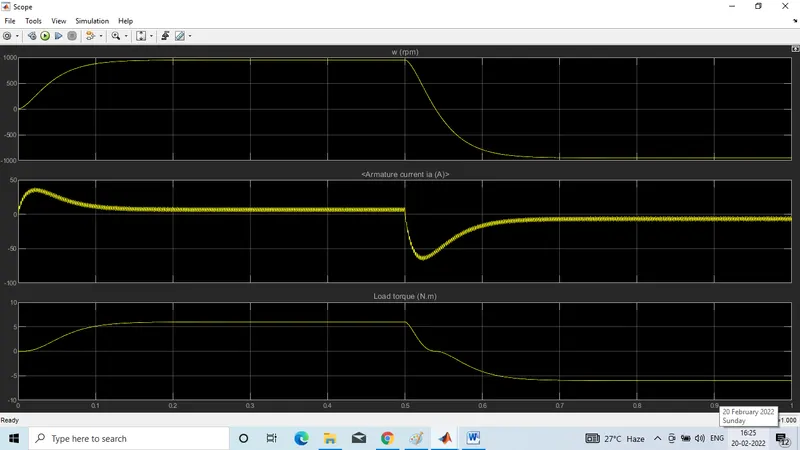
From the result scope we are getting.
Speed of motor:
- Initially increases to 0 to nearly 900 rpm upto 0.5 secs(Forward motoring action takes place).
- Then speed reduces to 0rpm(Forward dynamic breaking action takes place).
- Then speed increases from 0 to -900 rpm at upto 1 sec(Reverse motoring action takes place).
- Then reverse dynamics breaking occurs(Not shown in scope).
Load torque of motor:
- Initially torque increases from 0 to 0.5 secs in forward motoring action.
- Then torque reduces to 0Nm in forward dynamic breaking mode.
- Then torque increases in reverse direction in reverse motoring action upto 1 sec,
- Again torque reduce to zero(Not shown in scope).
(b) Armature current shoot up in motor:-
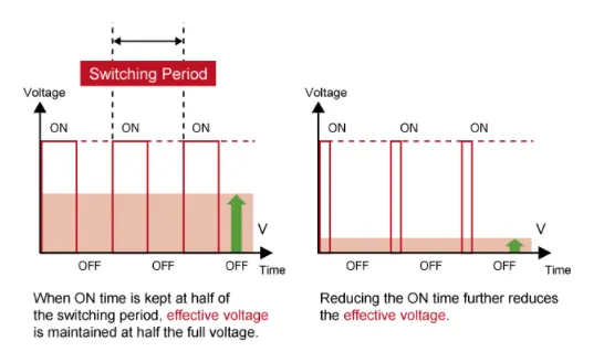
Here the initial current shoot up is due to sudden increase in voltage which inturns regulated by duty cycle. In this case motor driven in 75% of duty cycle i.e. 0.75*240=180V
We can change the duty cycle to 50%(120V) and seen the results as,
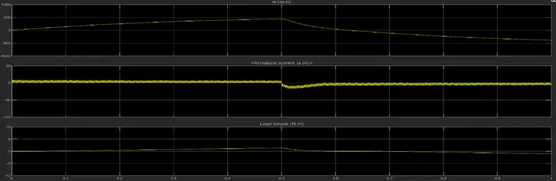
sudden shootup canceled in starting condition but slight shootup after 0.5 sec in reverse motoring condition. Again changeing the duty cycle to say 35%, we get the result as,
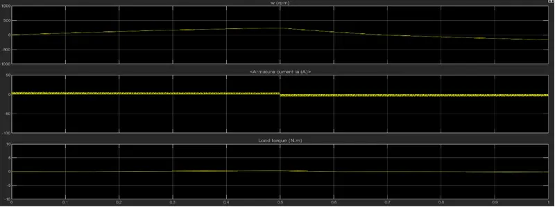
The shootup of current get dimlished on both the ends.
Conclusion:-
Thus to reduce the shootup armature currents we have to change the duty cycle gradually from 0 to 100% that inturns increases voltage gradually and speed also changes accordingly.
(c) Comparing the four quadrant chopper Dc drive (DC7) block with H bridge model:
Block:
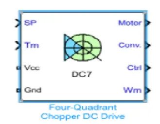
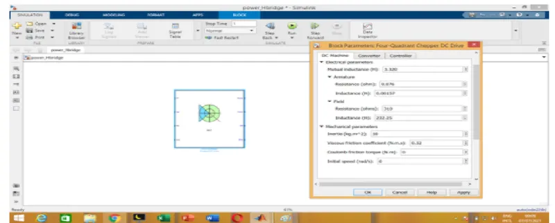
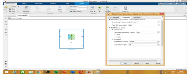
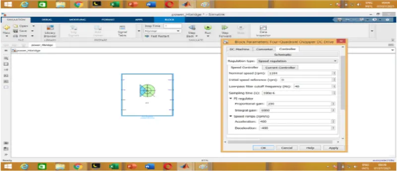
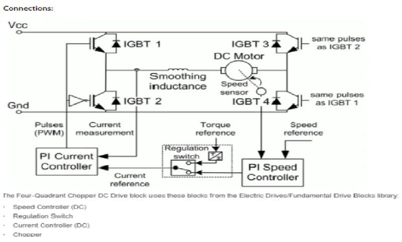
Inputs and outputs:
Armature voltage, speed reference, motor torque reference are given as inputs.
Motor, converters, controller, motor angular speed are get as outputs.
Working:
- Here four lgbt switches are used.
- Here pulses are given from PI current controller, that controls the pulses by comparing armature current measurement and current reference.
- Current reference can be generated by using regulation switch in that torque reference and PI speed controller pulses, that internally compared by speed of motor and reference speed given as input.
- Mainly speed controlled by current controller.
- In this case four quadrant operations are performed.
- Forward motoring mode, forward regenerative breaking mode Q1, Q4 are on and Q2, Q3 are in off.
- Reverse motoring mode, reverse regenerative breaking mode:Q@,Q3 are on Q1,Q4 are in off.
Comparison:-
- In DC7 chopper model speed controlled by varying current pulses from PI current controller and in H-bridge model speed controlled by varying duty cycles voltages.
- Here regenerative breaking in occuring while in H-bridge model breaking is occured by changing polarity of current flow, dynamic breaking occurs in it.
- In four quadrant Dc chopper model smoothing inductance is used for smooth increase and decrease in current flow which inturns controlling the motor speed smoothly,while in H-bridge it is not present. Here the operation is discrete and in H-bridge model it is continuous.
- Hence 4 quadrant DC choppers are used mostly in electric vehicles.
2). Two- quadrant chopper operating using simulink.
Objective:
To create a model for control of DC motor using two quadrant type C model DC chopper.
Chopper model:
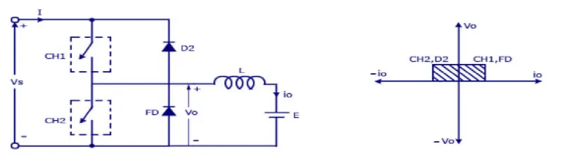
where,
Vs=DC voltage source
CH1= Power electronics switch1
CH2= Power electronics switch 2
D2,FD= free wheeling diodes
L=inductor load
E=Back emf from load
Mode of operation:
- Here either one should be ON at a time,either CH1 or CH2.
- If CH1 is ON the current flows from source +ve to load(here DC motor), passes through L and E to -ve terminal of source.(1st quadrant)
- If CH1 is off the, FD diodes conducts and complete the circuit (L-E-FD-L) as stored energy in inductor l. The voltage across is also positive voltage, current direction also positive.
- Now if CH2 is on, current flow from E(load current) completes the circuit(L-CH2-E).
- If CH2 gets off, the current passes through D2 towards source completes the circuit(E-L-D2-+ve source--ve source-E).
- In this stage regenerative breaking occurs(2nd quadrant).
- This cycle continuous again upto stop time.
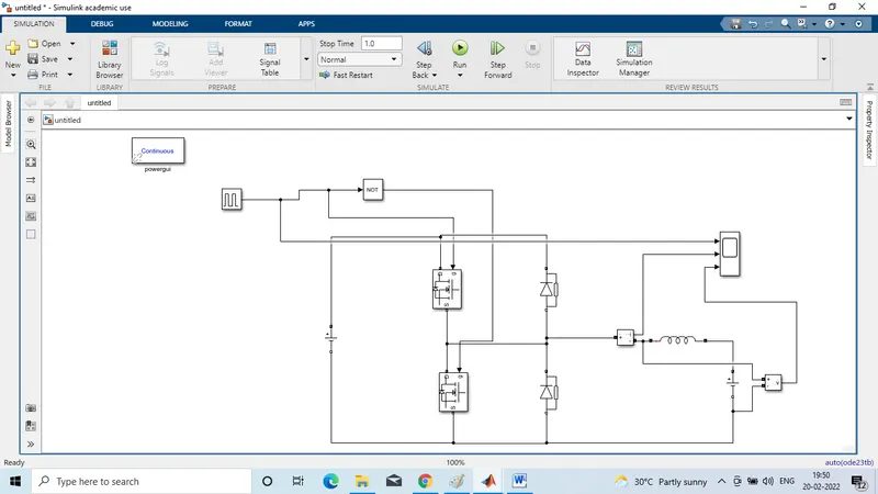
- Double click on MOSFET and DIODE block to disable(uptick show measurement port ) and rotate the diode in upward direction as per our requirement (source should be facing in downward direction for MOSFET and for DIODE source should be in upward direction)
- Open series RLC band block and change the branch type to (L) with default value 1milliH,once done arrange according to circuit diagram.
- We will be giving the tapping for the pulse gate terminal for 1 switch CH1 and from NOT gate we are giving it to other switch CH2. So if CH! is conducting CH2 will not conduct because we are using the NOT gate.
- Once donewe will be measuring the voltage by connecting its 1st port at staring of inductor and other to DC2 supply which is connected adjacent.
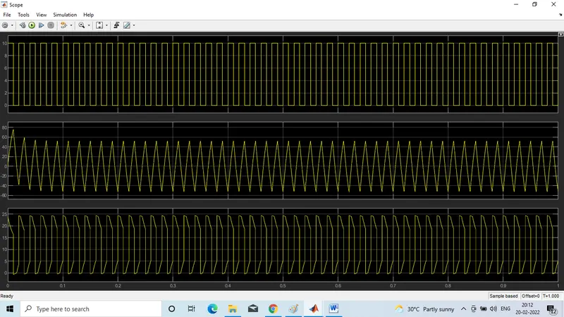
- And output is connected to 1st of the 3 port of scope input,current measurement port is also connected to 2nd port of scope and 3rd port is taken from output of pulse generator.
- Open pulse generator block set amplitude to 10 for better viewing,time period set to 0.02sec,pulse width is 50(because we 50% to be on and 50% to be off) i.e. NOT gate is on when 50%off
- Now set the simulation time for 1 sec and RUN the simulation.
3) BLDC motor operations:-
BLDC motor named as brushless dc motor having high efficiency than other types of motors. This motor is also known to be synchronous motor.
Construction:
Most of the motors are having brushes in their rotor as it transfer current into the rotor circuit but here differently rotor is placed with permanent magnet.
The stator coil is wounded with coils, they are stationary but producing variable DC voltages for rotating the permanent magnet as changing the magnetic field of stator poles continuously.
The controlling of motor is by changing the magnitude and direction of current flowing through the stator winding.
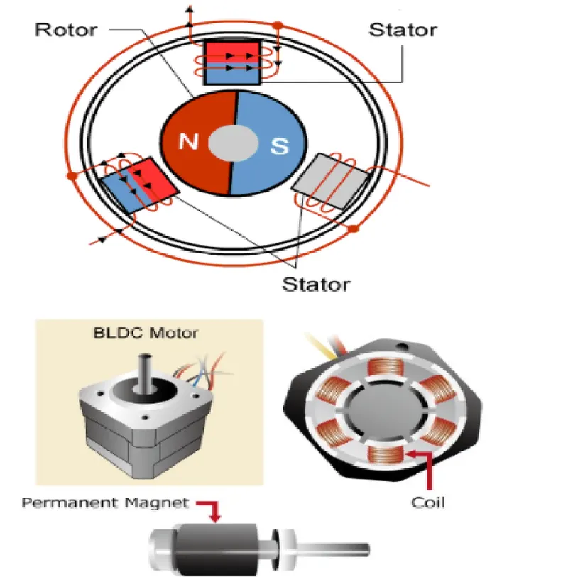
A BLDC motor with three coils on the stator will have six electrical wires(two to each coil) extending from these coils. In most implementations three of these wires will be connected internally,with the three remaining wires extending from the motor body.Wiring in the BLDC motor case is more complicated than simply connecting the power cells positive and negative terminals. we will look more closely at how these motors work in the second session of this series.
Operation of BLDC motor:
We can consider three winding terminal are coming out as U,V,W and their another ends are connected in single point as shown in below fig. the angle shift between two coils makes 120 degree.
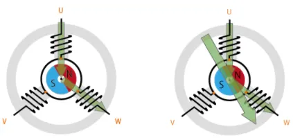
The current moves from U to W makes magnetizing the coils attracts the rotor consisting of permanent magnet makes moment as shown above to align with thr resultant arrow (larger arrow).
North pole of magnet towards arrow mark of resultant arrow.
Rotation is maintained by continually switching the flux so that the permanent magnet is constantly chasing the rotating magnetic field induced by the coils. In other words, energizing of U,V,AND W must be continually switched so that the resultant flux keeps moving, producing a rotating field that continually pulls on the rotor magnet.
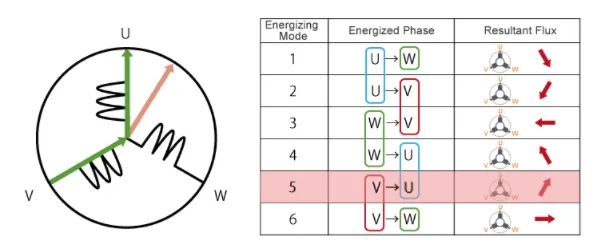
The above movement are acheived by continuous change in current direction over two poles of stator at single time. But this is slightly not continuous in their rotation. This makes motor vibration and noise will be produced. So, to attain smooth continuous rotation of rotor we have to control the current flow through all the three poles in same time.
As shown below we can achieve continuous change in current flow in all stator poles at same time in 120 degree phase shift.
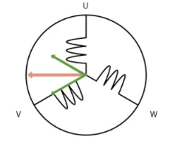
As we have seen, we drive BLDC motors by continuouslly changing the directionality of the flux produced by the coils. The permanent magnets on the rotor continually chase the shifting rotating magnetic field, causing the rotor to turn.This is the working of BLDC motor.
Advantage of BLDC motor:-
- One big advantage is efficiency,as these motors can control continuously at maximum rotational force(torque).
- Even small BLDC motors can deliver considerable power.
- BLDC motors can be controlled, using feedback mechanisms, to delivery precisely the desired torque and rotation speed.
- Reduced energy consumption and heat generation.
- BLDC motors also offer high durability and low electric noise generation.
- The sparks will not be produced as brushed motor between brushes and commutators.
Control of BLDC motor:-
By using the inverter circuitry to also adjust the voltage into each coil, we can control the magnitude of the current.A typical way to adjust the voltage is with pulse width modulation(PWM). We alter the voltage by lengthening or reducing the pulse on time(Duty Cycle the on time expressed as a ration of on+off switching interval). Increasing the duty cycle has the same effect as raising the voltage, reducing the duty cycle has the same effect as lowering the current.
PWM can be implemented using MPUs equipped with dedicated PWM hardware.while 120 degree conduction control only requires two phase voltage control. Sinusoidal control uses three phase voltage control and is considerably more complicated as appropriate inverter circuitry is therefore essential for driving BLDC motors.