Week-7 Challenge: DC Motor Control
1. A. Explain a MATLAB demo model named ‘Speed control of a DC motor using BJT H-bridge’.
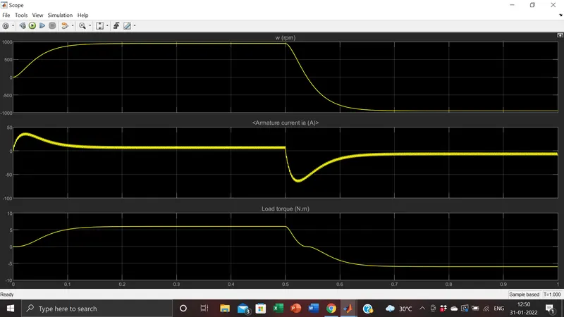
B. Comment on the armature current shoot-up from the scope results.
C. Refer to the help section of ‘The Four-Quadrant Chopper DC Drive (DC7) block’. Compare it with the H-bridge model.
Q1.ans}Initially the Model is opened in MATLAB help section---->Simulink page with the model opens.
Model Description
The Bipolar Junction Transistor (BJT) when used for power switching applications, operates as an IGBT. When it is conducting (BJT operating in the saturated region), a forward voltage Vf is developed between collector and emitter (in the range of 1 V). Therefore, the IGBT block can be used to model the BJT device.
The IGBT block does not simulate the gate current controlling the BJT or IGBT. The switch is controlled by a Simulink signal (1/0). The DC motor uses the preset model (5 HP 24V 1750 rpm). It simulates a fan type load (where Load torque is proportional to square of speed). The armature mean voltage can be varied from 0 to 240 V when the duty cycle (specified in the Pulse Generator block) is varied from 0 to 100%.
- The H-bridge consists of four BJT/Diode pairs (BJT simulated by IGBT models). Two transistors are switched simultaneously: Q1 and Q4 or Q2 and Q3.
- When Q1 and Q4 are fired, a positive voltage is applied to the motor and diodes D2-D3 operate as free-wheeling diodes when Q1 and Q4 are switched off.
- When Q2 and Q3 are fired, a negative voltage is applied to the motor and diodes D1-D4 operate as free-wheeling diodes when Q2 and Q3 are switched off.
- Also operating switches Q1 and Q3 as a pair and Q2 and Q4 leads to short circuiting.
- Current flows from positive to neagtive potential via the switch---motor----switch.
Load torque is calculated by multiplying the constant 'k' with angular velocity squared for diff speed.Also reducing the duty cycle of the pulse in the pulse genrator block reduces the overall voltage to work with in the circuit.
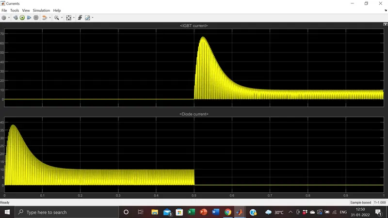
Graphs of model with 75% duty cycle
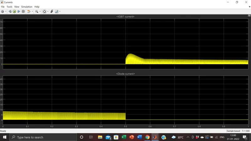
case 2:Graphs of model with 50% duty cycle
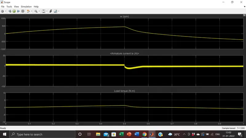
Q1.B.ans}nil
Q1.C.ans} C. Refer to the help section of ‘The Four-Quadrant Chopper DC Drive (DC7) block’. Compare it with the H-bridge model.
Four Quadrant operation of DC motor
This means a DC motor can operate in 4 differnt quadrants nmaely : 1st Quadrant-Forward motoring
2nd quadrant- forward braking
3rd quadrant- reverse braking
4th quadrant- reverse motoring
In all the quadrants the chopper circuit has the ability to control the amnt of dc voltage received by the motor.It acts as DC-DC converter.
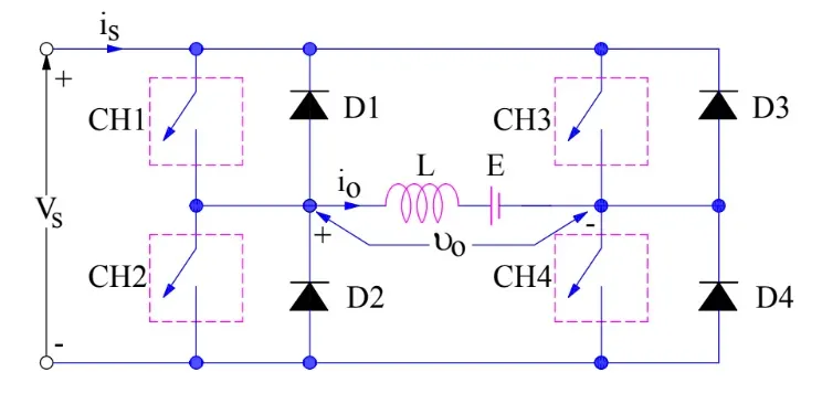
- When switch CH1 and CH4 are turned ON , the inductor L will store will store energy and this chopper operates in 1st quadrant.
- When CH1 and CH4 are turned off,the inductor will release its energy causing the diodes D2 ANDD3 to conduct and this chopper operates in 4th quadrant.
- For third quadrant operation, CH1 is kept off, CH2 is kept ON and CH3 is operated. When CH3 is ON, load gets connected to source and hence load voltage is equal to source voltage.Polarity of load voltage vo is opposite to what shown in the circuit diagram. Hence, vo is assumed negative. Let us now see what is the status of load current io. It may be seen that io is flowing in the direction opposite to shown in the circuit diagram and hence negative.
-
To obtain second quadrant operation, CH2 is operated while keeping the CH1, CH3 & CH4 OFF. When CH2 is ON, the DC source in the load drives current through CH2, D4, E and L. Inductor L stores energy during the On period of CH2.When CH2 is turned OFF, current is fed back to the source through D1, D4.
Comparison Between Four Quad Chpper and BJT H Bridge
- In 4 quadrant chopper DC drive requires current supply for each sector ie all 4 quadrants.Whereas for H bridge needs it in only 2 sectors namely:Forward motoring and reverse motoring.
- Modern battery technology charger uses H bridge circuit whereas 4 quad chopper is requires in industrial/commercial application.
- The efficiency is highin chopper compared to bridge.
- In H bridge we need to change the polariy /which turns int opposite direction to ensure motor control whereas in chooper we need to interupt a signal under the control of another.
Q2.ans}Develop a 2-quadrant chopper using simulink & explain the working of the same with the relevant results
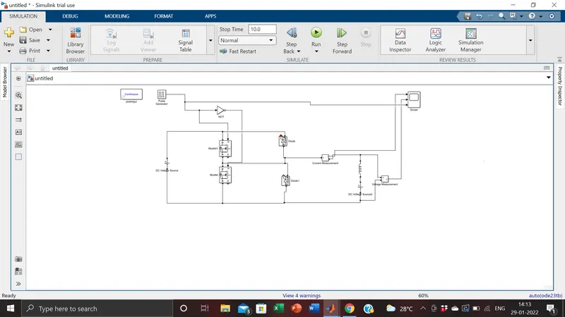
2 quadrant chopper circuit construct in simulink
Graph
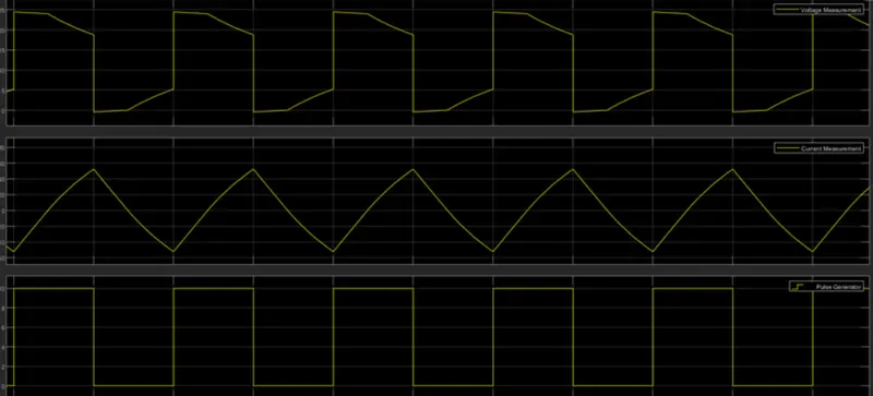
- The pulse generator block creates a pulse.---->the NOT gate is used so that the mosfet will not closed at the same time,or eles a short circuiting may occur.When the mosfet is ON the other one is off and vice versa.
- The amplitude is set to 10 as suggested so that the pulse is een on the scope.T.P=0.02s and width ne 50%/
- The circuit is connected as shown above.It is constructed with reference to a circuit diagram of the 2 quad chopper.We use 2 mosfets,2 diodes,2 DCC power sources an inductor.
- Also in addition voltmeter,ammeter and scope blocks to view results.
- The main Dc source on the left of the circuit is set to 24 v.the inductor works as load.Another source of 12v is connected in series with the inductor.
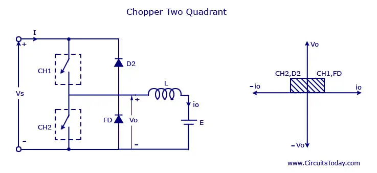
- The average voltage will be always positive but the average load current might be positive or negative.
- The power flow may be life the first quadrant operation ie from source to load or from load to source like the second quadrant operation.
- The two choppers should not be turned on simultaneously as the combined action my cause a short circuit in supply lines.
- For regenerative braking and motoring these type of chopper configuration is used.
Q3.ans Explain in a brief about operation of BLDC motor.
A brushless DC motor is an electronically commuted DC motorwhich does not have brushes. The controller provides pulses of currentto the motor windings which contro the speed and torque of the synchronous motor.
These types of motors are highly efficient in producing a large amount of torque over a vast speed range. In brushless motors, permanent magnets rotate around a fixed armature and overcome the problem of connecting current to the armature. Commutation with electronics has a large scope of capabilities and flexibility. They are known for smooth operation and holding torque when stationary.
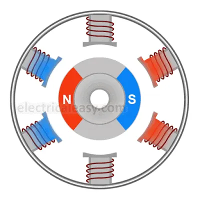
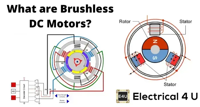
Brushless DC motor has only two basic parts: rotor and the stator. The rotor is the rotating part and has rotor magnets whereas stator is the stationary part and contains stator windings. In BLDC permanent magnets are attached in the rotor and move the electromagnets to the stator. The high power transistors are used to activate electromagnets for the shaft turns.
Simple Working
Stator windings of a BLDC motor are connected to a control circuit (an integrated switching circuit or inverter circuit). The control circuit energizes proper winding at the proper time, in a pattern which rotates around the stator. Permanent magnets on the rotor try to align with the energized electromagnets of the stator, and as soon as it aligns, the next electromagnets are energized. Thus, the rotor keeps running.