Week-7 Challenge: DC Motor Control
AIM: To Answer the below Queries of Week 7 Challenge
1. A. Explain a MATLAB demo model named ‘Speed control of a DC motor using BJT H-bridge’.
B. Comment on the armature current shoot-up from the scope results.
C. Refer to the help section of ‘The Four-Quadrant Chopper DC Drive (DC7) block’. Compare it with the H-bridge model.
2. Develop a 2-quadrant chopper using simulink & explain the working of the same with the relevant results. (Refer to article - Multiquadrant operation of motor )
3. Explain in a brief about operation of BLDC motor.
METHODOLOGY:
1. A. Explain a MATLAB demo model named ‘Speed control of a DC motor using BJT H-bridge’.
BJT : It is a type of transistor that uses electrons and holes as charge carriers giving the name Bipolar Junction Transistor. It consist of 3 terminals namely
E- emitter
B- Base
C- Collector
The current is said to flow through the emitter and collector, whose flow is controlled by the voltage in base.
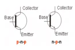
BJT's use semiconductor of 2 types namely PNP and NPN.
H Bridge: It consist o four BJT/Diode pairs in which two transistors are switched simultaneously.
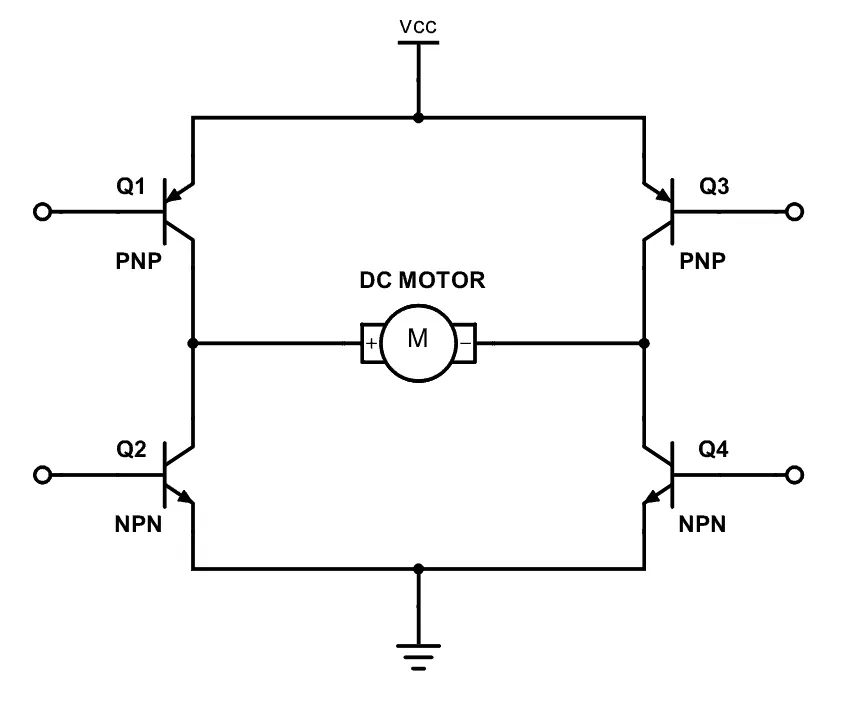
Q1 and Q4 are fired: A positive voltage is applied to the motor and diodes 02-03 operate as free-wheeling diodes when 01 and 04 are switched off.
Q2 and Q3 are fired : A negative voltage is applied to the motor and diodes 131-0/ operate as free-wheeling diodes when 02 and 03 are switched off.
The model is opened using the documentation available in help section of simulink workspace. Run the model and analyse the graph in scope,
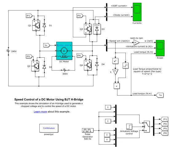
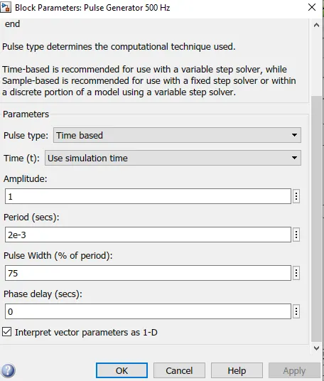
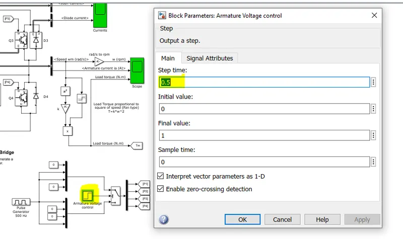
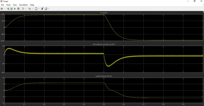
Inference: From the above block parameters and graph it is is clear that shoot up in armature current is vissible when the poles are reversed. The motor by default starts in posistive direction with duty cylcle = 75% and mean DC Voltage 180V. At t=0.5, the armature voltage will reverse and motor will run in the negative direction.
75% duty cylce mean: 75% time of one cycle the voltage is given to the motor and remaining 25% of time the motor is on off stage ie; no voltage is received from source. By varying the on and off state duty cycles --> Voltage is varied and thus the speed of the motor is controlled.
Shoot Up:
At starting of the motor and at t=0.5 armature current shoot up is observed.
Armature Vs Time Graph 2:
Reason for Shoot up: Whenever the armature voltage reverses its direction the shoot up phenomena is observed. Initially the shoot up is seen after that it becomes stable until 0.5 sec and agin there is a sharp increase in armature current that again decreases and becomes stable. This phenomena repeats when the next cycle begins.
Solution to Shoot up:
Vary the pulse width - Reduce the pulse width from 75% to 50%
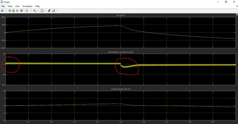
Inference: There is a decrease in armature current shoot up initally for the positive direcetion of armature voltage but at t=0.5 sec time mark the armature voltage is reversed the armature current shoot up in the negative direcetion is visible. ( compare to 75% pulse width the shoot up is less)
Again reduce the pulse width to 40% and rerun the simulation: Shown below
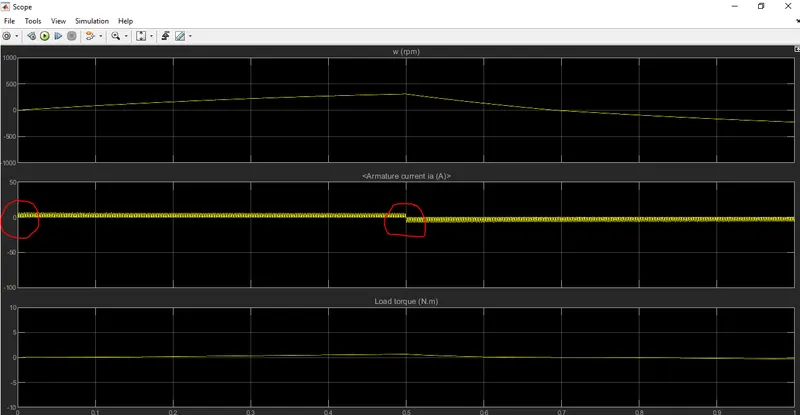
Inference: There is no armature shoot up observed at positive armature voltage direction initially. At reversal of direction the armature current increases from 7A to -7A and matintains the same. Shoot up as before is not seen now.
C. Refer to the help section of ‘The Four-Quadrant Chopper DC Drive (DC7) block’. Compare it with the H-bridge model
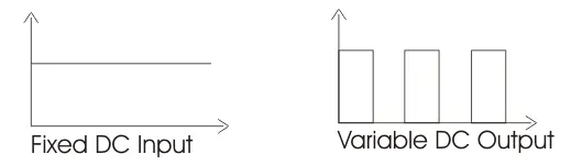
DC Chopper: A DC-DC convertor used to obtain a vairiable DC from cosntant DC input. Two types step down and step up choppers.
Below the DC7 chopper Circuit:
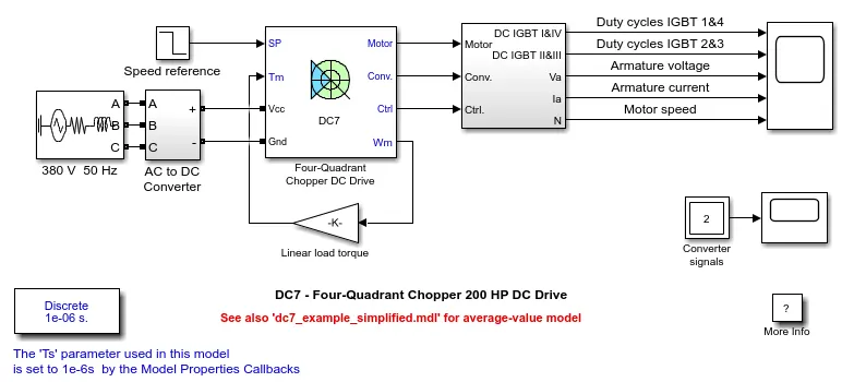
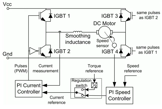
Inference: 200 HP DC motor is excited separately by a constant 150 V DC voltage source and armature voltage is given by IGBT convertor which is inturn controlled by 2 PI regulators. 515 V DC bus obtained by rectification of 380V AC 50HZ voltage source fed the converter. A braking chopper is added beteween the diode rectifier and DC7 block to limit DC bus voltage during dynamic braking.
Speed regulator - outputs the armature current referecne which is used by current controller in order to obtain the torque required to achieve desired speed. The speed reference change rate follows acceleration and decleration ramps to avoid armature over-current and destabilization.
Current Regulator: It controls the armature current by computing the appropritate duty ratios of the 5kHz pulse of the four IGBT devices. For proper system beahviour, the instantaneous pulse values of IGBT devices 1 and 4 are opposite to those of IGBT 2 and 3. this will genrate average armature voltage required to get desired armature current.
Inductance: Placed in series with armature circuit to limit the amplitude of current oscillations
H-BRIDGE:
It is a simple circuit that is used to control the DC motor (backward or forward). When Q1 and Q4 is active the positve is connected to left of motor and negative to the other side then motor starts to rotate in one direction. Similarly if Q2 and Q3 is active then the plus is on the right and minus is on the left of motor. Now motor rotates in opposite direction.
Comparison with H bridge:
Both BJT-H bridges and 4 quadrant choppers have pros and cons.
BJT_H bridges:
capable of braking operation without air resitance or friction brakes to bring motor to rest. But Reverse breaking and forward breaking is not possible
Not capable of regenerative braking
Polarity of current is reversed to change the direction of motor
Current values are continuious and or not chopped
PI controller is used to control speed which is absent in H-bridge
Applications: Used in robotics and electro-mechanical devices
4 Quadrant DC chopper
capable of braking operation without air resitance or friction brakes to bring motor to rest. Reverse breaking and forward breaking is also possible
Capable of Regernerative braking.
current signals are interupted with one another to change the direction of motor
Current values are chopped and not continuous as seen 4 quadrant DC Chopper
PI controller is used to control speed
Applications: Used in Automobiles
2. Develop a 2-quadrant chopper using simulink & explain the working of the same with the relevant results. (Refer to article - Multiquadrant operation of motor )
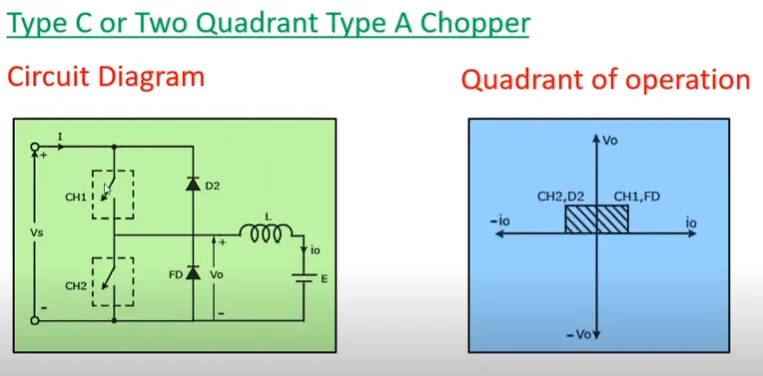
Circuit Diagram:
Methodology:
Circuit Simulink:
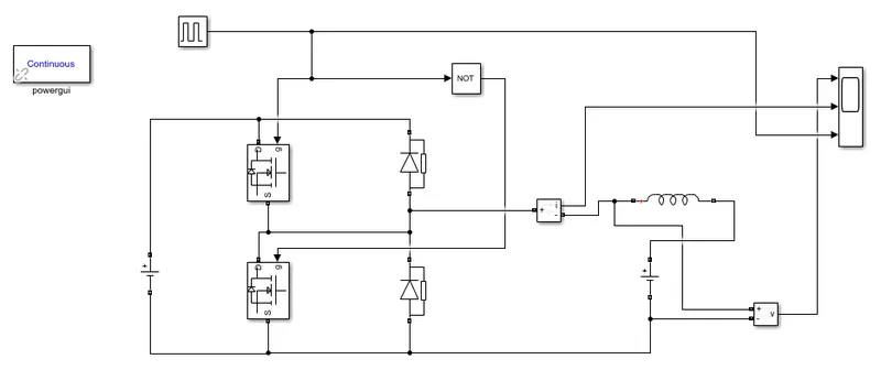
Working: Two Quadrant chopper C- Type is obtained by connecting Type A and Type B choppers in parallel. It is used for motoring and regenerative braking.
Output voltage is always positive w.r.t first and second quadrant also positive: When CH2 and FD is connecting the voltage is short circuited and voltage is zero.
Cases:
CH1 and FD is connected Current is positive and Voltage: Vo is also positvie
CH2 and D2 is connected Current is negative and Voltage: Vo is also positvie
Forward and reverse regeneration is possible by 2 quatrant chopper
Parameters:
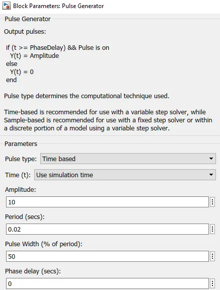
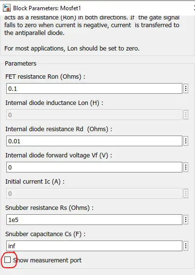
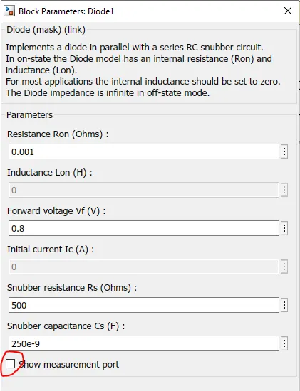
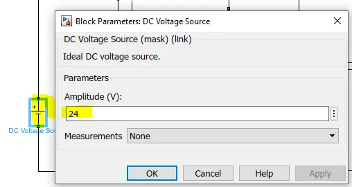
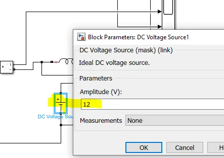
Output:
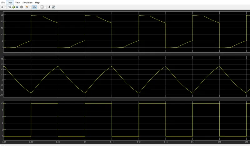
Inference:
- Voltage wave form is not seen below zero so it is always in positive direction
- Average Load Current wave form swtiches from positive to negative based on the switching action
- Amplitidue is 10 as given
Thus the circuit is Type C chopper or 2-quadrant chopper
Advantages:
Simplicity in circuit
Lower Armature current ripple
3. Explain in a brief about operation of BLDC motor.
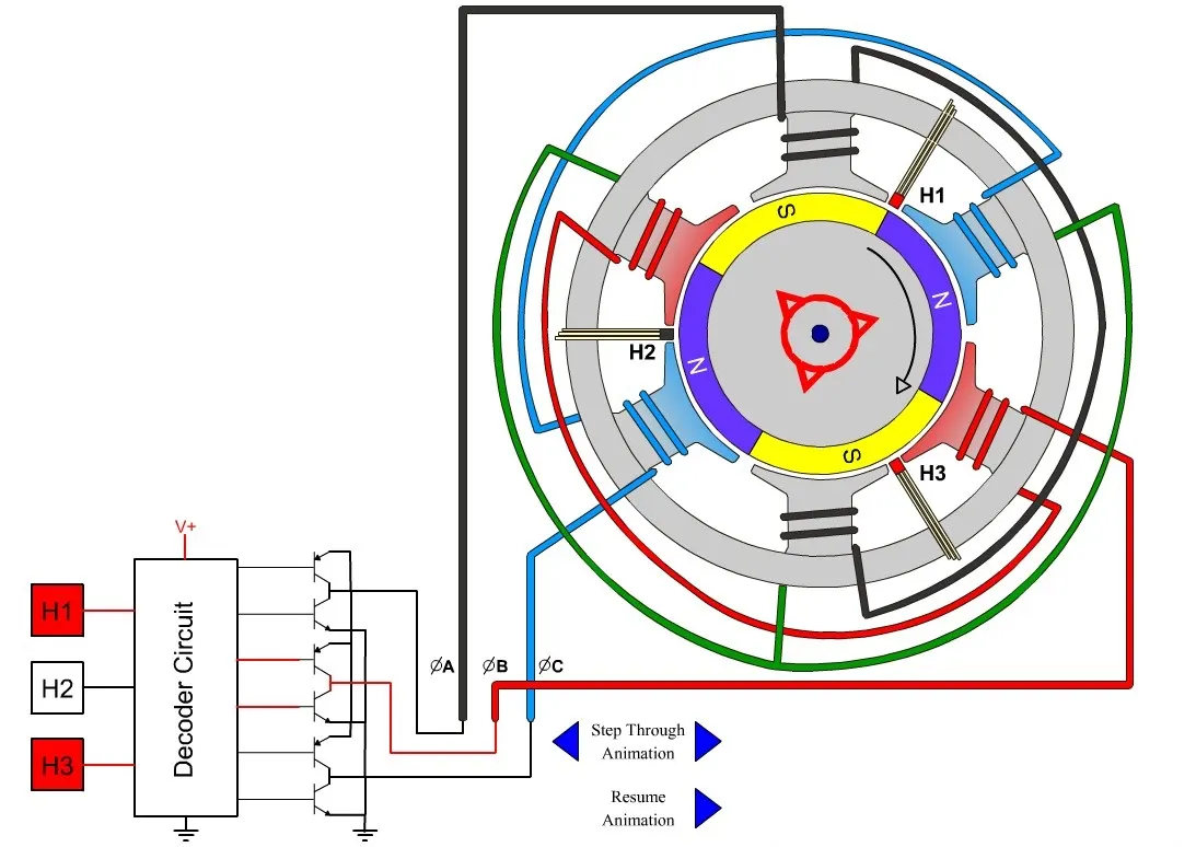
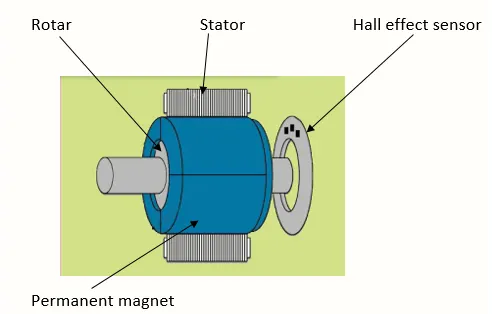
Working:
A BLDC Motor is synchronous motor in the sense that the magnetic field generated by the stator and the rotor revolve at the same frequency. Here the commutor is replaced by electric switch.
It works on the principle of Lorentz force law which states that whenever a current carrying conductor placed in a magnetic field it experiences a force. As a result of reaction force, the magnet will experience an equal and opposite force. In the BLDC motor, the current carrying conductor is stationary and the permanent magnet is moving.
Stator coils get a supply from source and act as electromagnet by producing uniform field in the air gap. Though the source of supply is DC, switching makes to generate an AC voltage waveform with trapezoidal shape. Due to the force of interaction between electromagnet stator and permanent magnet rotor, the rotor continues to rotate.
Advantages:
- Less overall maintenance - no brushess
- Smaller in Size
- Higher speed range
- It has no mechanical commutator and associated problems
- Lower electric noise generation and electromagnetic interference
Disadvantages:
- Costly
- Comples drive circuit
- Additional sensors and electronic controller
Applications:
- Washing machines, compressors and dryers
- Fans, pumps and blowers, Hard drives, CNC motors