DC Motor Control
AIM
- Run MATLAB demo ‘Speed control of a DC motor using BJT H-bridge’. Modify the model such that armature current doesn’t shoot up when motor changes direction from forward to reverse.
- Refer to the help section of ‘The Four-Quadrant Chopper DC Drive (DC7) block’. Compare it with H-bridge model.
- Make a suitable EV model using DC7 block and make result report.
Solution 1:
The given model shows the simulation of an H-bridge used to generate a chopped voltage and control the speed of DC Motor. The given model consists of the Bipolar Junction Transfer(BJT) as the power switching applications operated as an IGBT.
The switch is controlled by a Simulink signal(1/0). The DCC motor uses the preset model (5 HP 24V 1750 rpm). It simulates a fan type load, where load torque is proportional to the square of speed.
The armature voltage can be varied from 0 to 240V when the duty cycle can be varied from 0 to 100%.
BJT(Bipolar Junction Transistor)
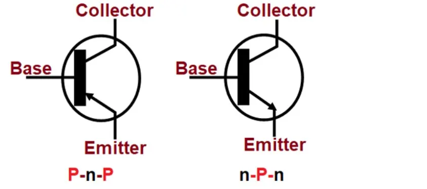
- A BJT is a three-terminal semiconductor device. The name "bipolar" comes from the fact that this type of transistor contains two types of semiconductor material—one positive type (p-type) and one negative type (n-type)—through which a current flows.
- Bipolar junction transistors usually contain silicon. Moreover, impurities are commonly added to the silicon via doping to make the layers behave as desired.
- It's the p-type layers in a BJT's job to attract the electrons that enter the transistor through its input circuit. The n-type layers, on the other hand, should encourage electrons to flow out of the transistor. This push-and-pull effect between the layers enables the electrical current to be amplified and controlled.
- The configuration of the layers in a BJT determines the electrical current's flow and ensures that a charge can't return in the same direction as it came. This setup protects the system from overheating or becoming damaged.
BJTs are created by layering p-type and n-type silicon to form a three-layer “sandwich”:
- The base, to which a small starting current is attached.
- The emitter, which emits electrons
- The collector, which collects the electrons that have been amplified. Electrons are passed between from the emitter to the base.
Then bipolar transistors have the ability to operate within three different regions:
- Active Region – the transistor operates as an amplifier and Ic = β*Ib
- Saturation – the transistor is “Fully-ON” operating as a switch and Ic = I(saturation)
- Cut-off – the transistor is “Fully-OFF” operating as a switch and Ic = 0
There are two types of sandwiches: NPN (negative-positive-negative) and PNP (positive-negative-positive). The former switches on when the current flows through the base, while the latter switches on only when there’s no current in the base.
BJT H- Bridge
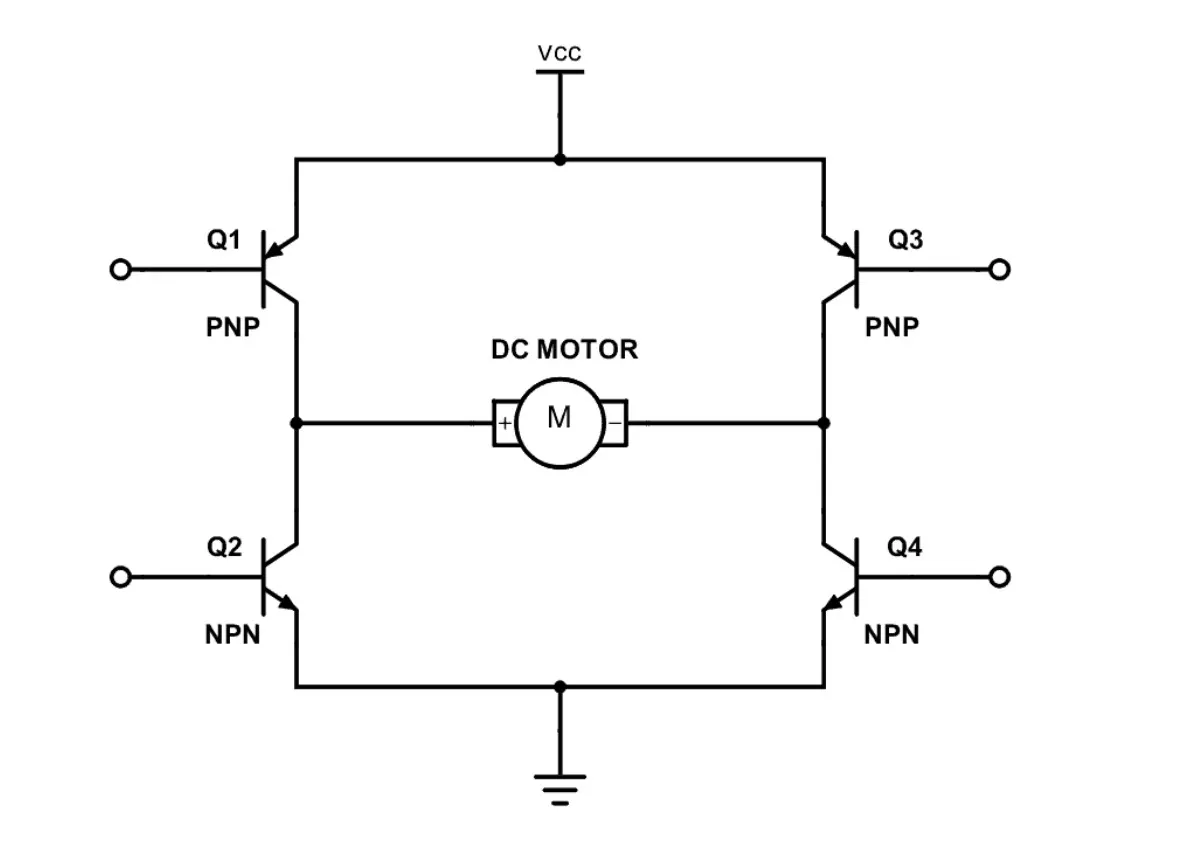
An H-bridge is an arrangement of transistors that allows a circuit full control over a standard electric DC motor. That is, an H-bridge allows a microcontroller, logic chip, or remote control to electronically command the motor to go forward, reverse, brake, and coast.
The H-bridge consists of four BJT/Diode pairs (BJT simulated by IGBT models). Two transistors are switched simultaneously: Q1 and Q4 or Q2 and Q3. When Q1 and Q4 are fired, a positive voltage is applied to the motor, and diodes D2-D3 operate as free-wheeling diodes when Q1 and Q4 are switched off. When Q2 and Q3 are fired, a negative voltage is applied to the motor, and diodes D1-D4 operate as free-wheeling diodes when Q2 and Q3 are switched off.
The model which is created in Simulink is shown below :
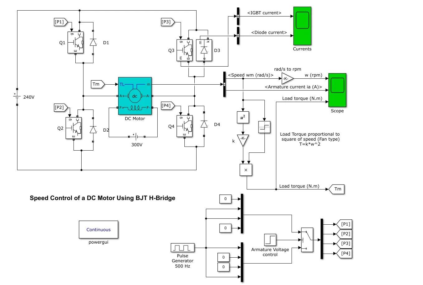
The motor starts in a positive direction with a duty cycle of 75% (mean DC voltage of 180V). At t= 0.5 sec., the armature voltage is suddenly reversed and the motor runs in a negative direction.
'Scope' shows motor speed, armature current, and load torque and 'Currents' shows currents flowing in BJT Q3 and diode D3.
RESULT
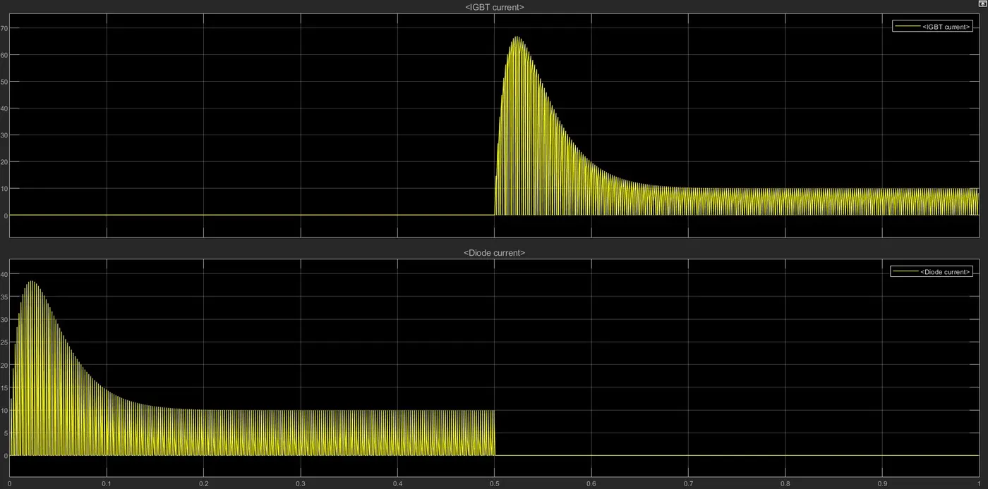
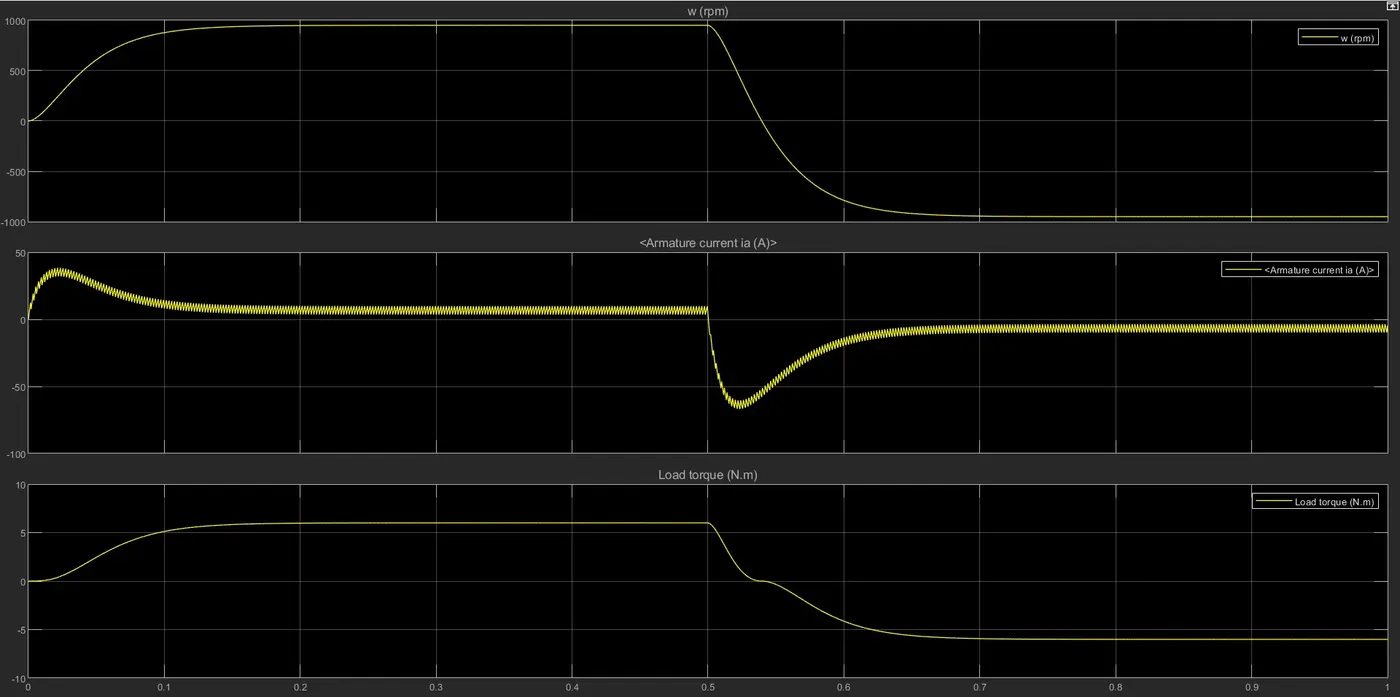
- The given cycle runs for a 75% duty cycle, which means the program is ON for 75% of the time and off for 25% of cycle time.
- For the given plot we can see that for Q3 and Q4 the input is provided after 0.5 sec, so IGBT signal is present after 0.5 sec to 1sec.
- As for the first cycle we can see that the diode current passes, which indicates current passes through the circuit, and after 0.5 sec there's no diode current which indicates there's no current passes through the circuit or the current passes in the reverse direction.
- From the given plot we can see that the motor took around 0.1 sec to reach the maximum rated speed it is because of the load applied.
- In Q3 mode the motor starts reducing speed or works in reverse mode and reaches a maximum speed of -1000 rpm.
- We can see the armature current overshoot when it changes direction, due to the load applied and again reaches its constant current supply because of constant speed.
Reducing the armature current shoot up when changes the current direction
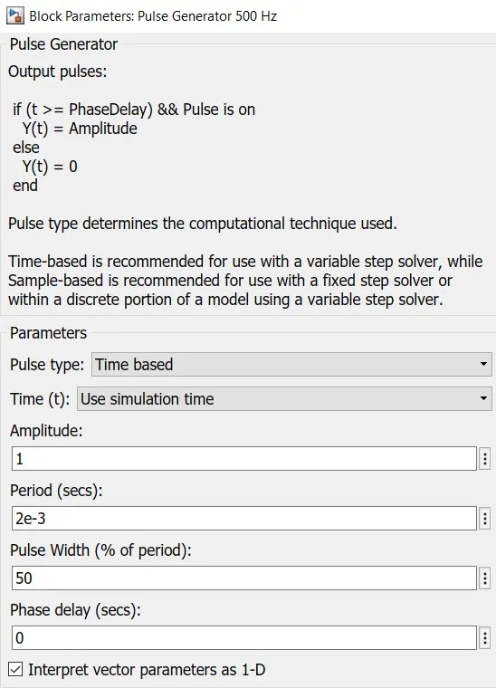
We can reduce the shoot up of motor current when changing direction by reducing the duty cycle to 50%.
RESULT
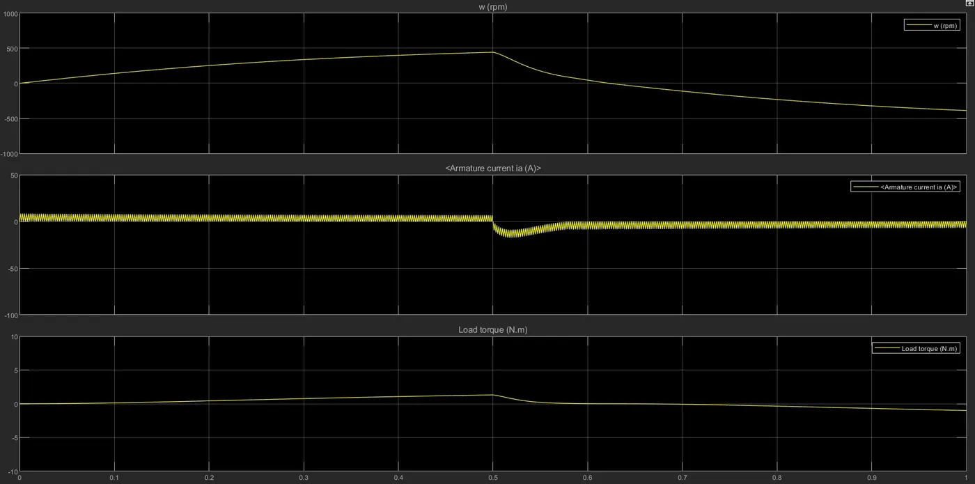
We can see by changing the duty cycle to 50% the shoot up of armature current when changing direction has been reduced.
Solution 2:
The Four-Quadrant Chopper DC Drive (DC7) block
The four-quadrant Chopper DC drive, blocks represent the four-quadrant, DC-supplied chopper drive for DC motor. The drive features the closed-loop speed control with the four-quadrant operation. The speed control loop output the reference armature current of the machine.
Using a PI current controller the chopper duty cycle corresponding to the commanded armature current is derived. This duty cycle is then compared with the sawtooth carrier signal to obtain required PWM signals to the chopper.
The chopper converts the fixed DC voltage to variable DC voltage. Self-commutated devices (directly on or off devices via a gate) like MOSFET, IGBT, power transistors, GTO, and IGCT are used for making choppers because they can be commutated by the low power control signal and do not need a commutation circuit.
The circuit diagram is shown below:
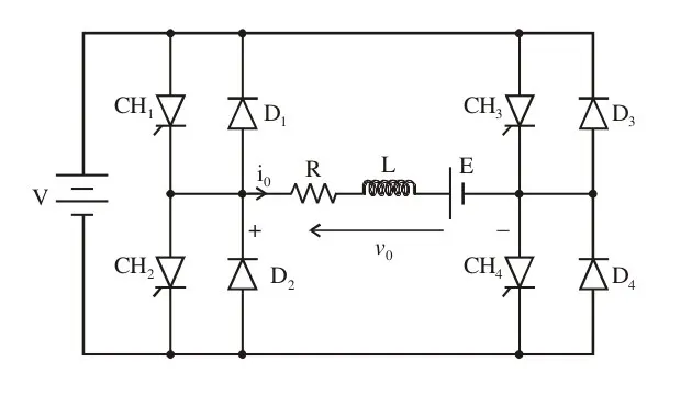
Four Quadrant Operation of DC Motor
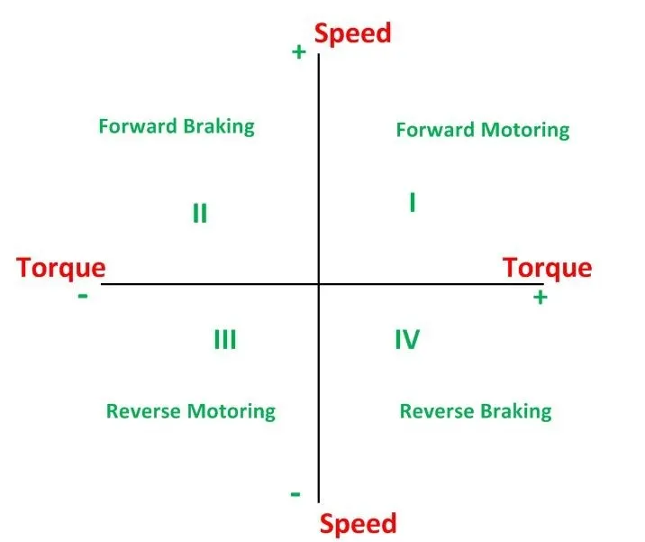
- When a motor draws power from supply, the voltage and current are in the same direction.
- Now the motor is said to be in motoring operation, its operation corresponds to the first quadrant.
- If there is a possibility of reversing the current direction keeping the voltage polarity the same, the motor is said to be operating in the second quadrant.
- This happens when regenerative braking is applied to the motor.
- During regeneration operation, reverse power flow will happen. ie, power will be fed back to the supply system.
- If the voltage polarity and load current are reversed simultaneously, the motor’s operation will be in the opposite direction ( but the power is consumed by the load).
- This operation corresponds to the third quadrant and even now it is said to be in motoring operation(in reverse mode)
- If the voltage polarity is reversed maintaining the current direction from source to load, the power reversed, and the operation corresponding to the fourth quadrant.
- Now the motor is said to be in reverse regeneration operation (ie, regeneration in the reverse direction).
Simulation
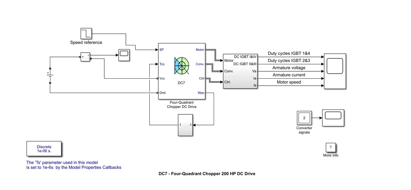
For the model, we have used a simple DC source as our energy source, and have given a voltage value of 240V.
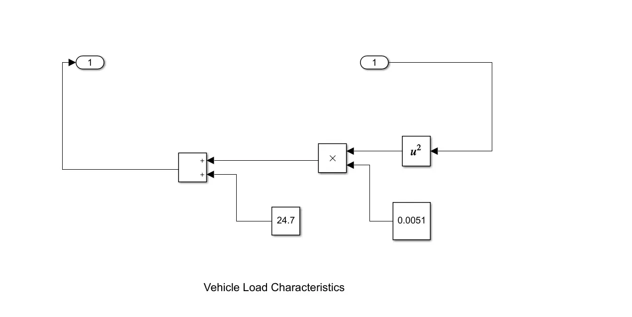
For the reference speed, we have used a simple step block, and we have also modeled the vehicle load characteristics for relating torque and speed of the vehicle.
The full model of the DC7 model is shown below:
RESULT
The four-quadrant is similar to the H-bridge model, which consists of Q1, Q2, Q3, and Q4 quadrant, of which Q1, Q4 works in the forward cycle and Q2, Q3 works in the reverse cycle.
It takes around 1-sec armature current to accelerate at full speed, as we can see for the first 2.5 sec, Q1 , Q4 receives maximum current and works in forwarding motion, while the reverse model Q2 and Q3 at 0 value means they are shut off.
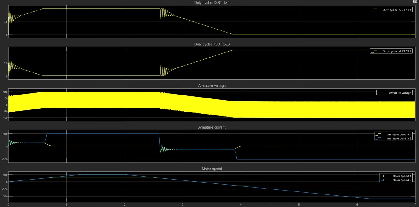
After the first half, the motor works in the reverse mode that's why Q2 and Q3 receive at current, and Q1 and Q4 receive 0 value. We can also see a change in the value of armature current for both cycles.
The armature current of the circuit seems to be fluctuating between 100V to -100V this is because as the power switch occurs between IGBT Q1, Q4, and Q2, Q3 the polarity of the voltage will reverse as it flow through the circuit.
Solution 3:
Comparison between the Four-Quadrant Chopper DC Drive (DC7) block’ and H-bridge model
Four quadrant dc chopper model required current for each sector and consists of four-quadrant forward motoring, forward regenerative braking, reverse motoring, and reverse regenerative braking, whereas H-bridge consists of two operations they are forward motoring and reverse motoring.
H-bridge circuit is used in robotics technology while four quadrant DC chopper circuits are used in industrial as well as commercial applications.
In a four-quadrant DC chopper, the current signal is interrupted with one another to change the direction of rotation of the motor. This can be done the speed reference provided to the motor, which speed value is converted to signal which interrupts one another to change the direction of the motor. But in BJT the polarity of the current is changed to change the direction of rotation of the motor.
In this model, a PID controller is used with the DC7 chopper model to control it but in the H-bridge model, this is not used.
Conclusion
Speed control of DC motor with H-bridge model and DC7 chopper model has been successfully performed.
The difference between both control model and their benefits has been successfully noted down.