Week-7 Challenge: DC Motor Control
1. Run MATLAB demo ‘Speed control of a DC motor using BJT H-bridge’. Modify the model such that armature current doesn’t shoot up when motor changes direction from forward to reverse.
To open the model use the command 'power_Hbridge' in the command window of MATLAB. On opening the model we get this model:
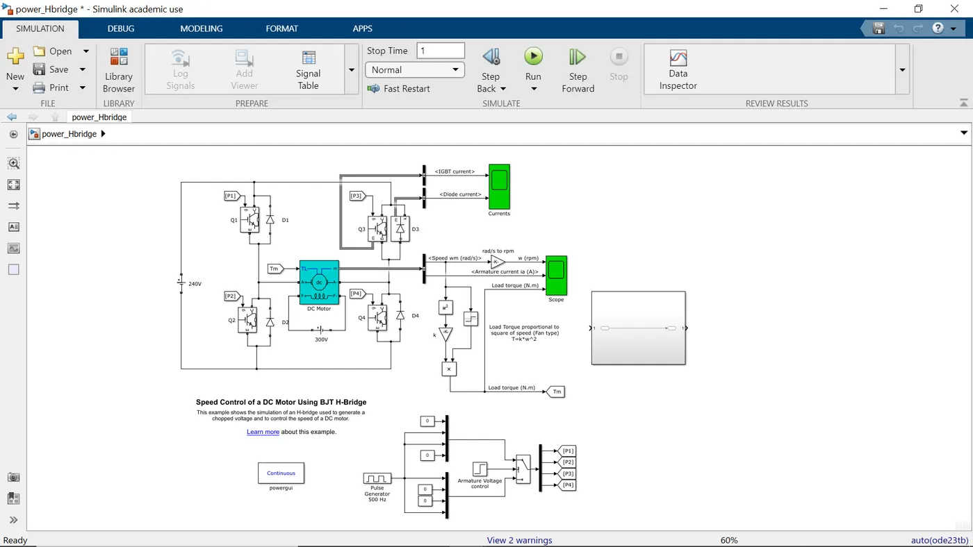
Figure. Speed control of a DC motor using BJT H-bridge
We see that there are four switches Q1, 2, Q3 and Q4. Q1 and Q4 are operated simultaneously and a positive voltage is supplied to the motor. Diodes D2 and D3 operate as freewheeling diodes when Q1 and Q4 are switched off. When Q2 and Q3 are fired a negative voltage is applied to the motor and diodes D1, D4 operate as free-wheeling diodes when Q2 and Q3 are switched off.
Keeping all the parameters of the model as default we run the model to get the following results:
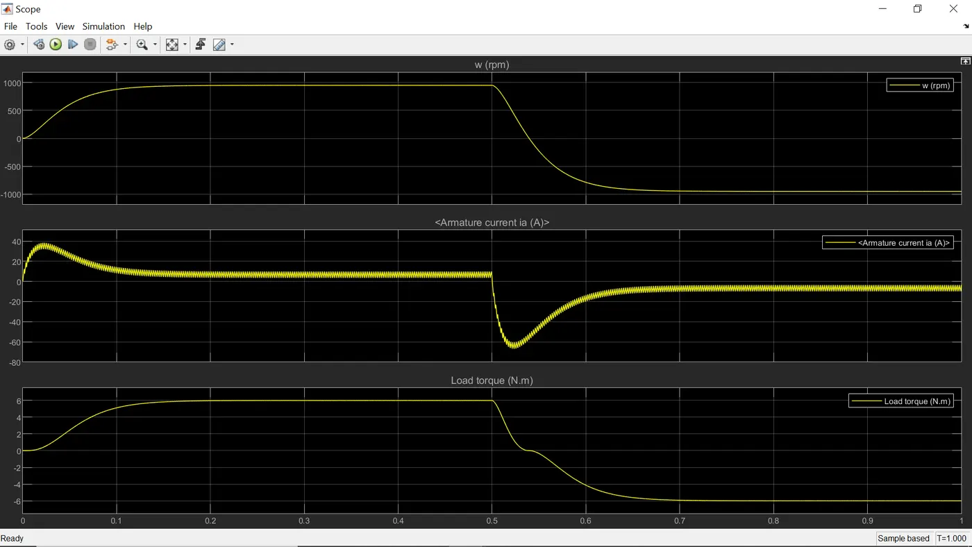
Figure. RPM, Armature Current and Load Torque plots
From the above plots we can see that during the switching of the direction of applied voltage there is a spike in the armature current. Even thought the spike duration is very less the power losses are very significant during switching. It can be up to a quarter of peak power losses.
As soon as the switch is open the voltage starts to buildup and there would be very less amount of current and this can lead to `I^2R` power losses. To avoid this we use a snubber circuit. Snubber circuit limits or stops switching voltage amplitude and its rate of rise.
In a snubber circuit as soon as the switch is open the current is diverted to a snubber which is initially uncharged. So the snubber will help prevent the voltage buildup and thus reducing the switching losses. This energy has to be dissipated somewhere. So when the switch is closed the snubber releases this energy through a resistor to slow down the discharge rate.
So in order to prevent the spike of armature current when switched from forward to reverse we have to increase the resistance (`R_(ON)`) of Q2 and Q3 to control the armature current discharge rate. We changed the `R_(ON)` to 5 ohms and we achieved a significant drop (from -70 A approximately to -23 A approximately) in the armature current during switching.
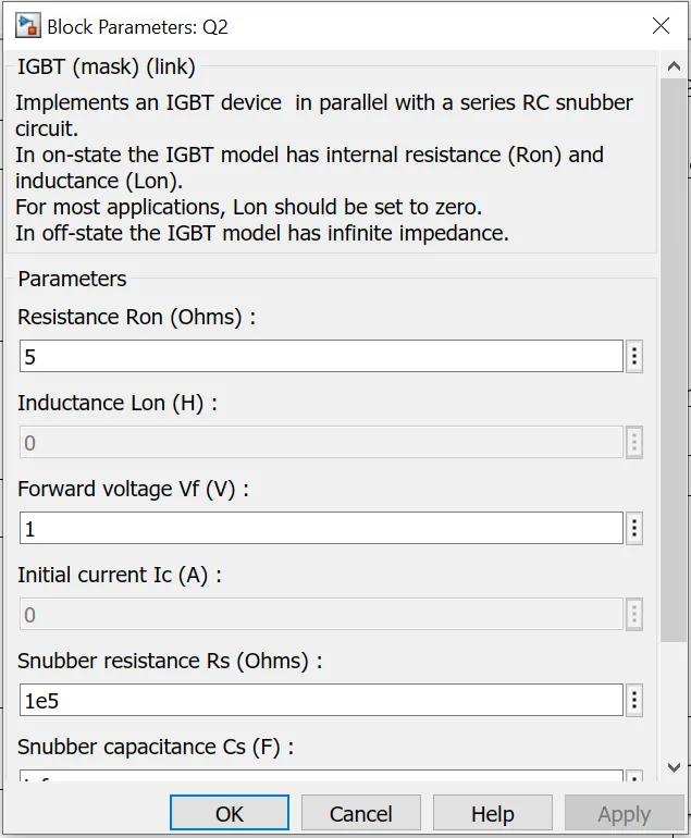
Figure. Block Parameters of BJT Q2 and Q3
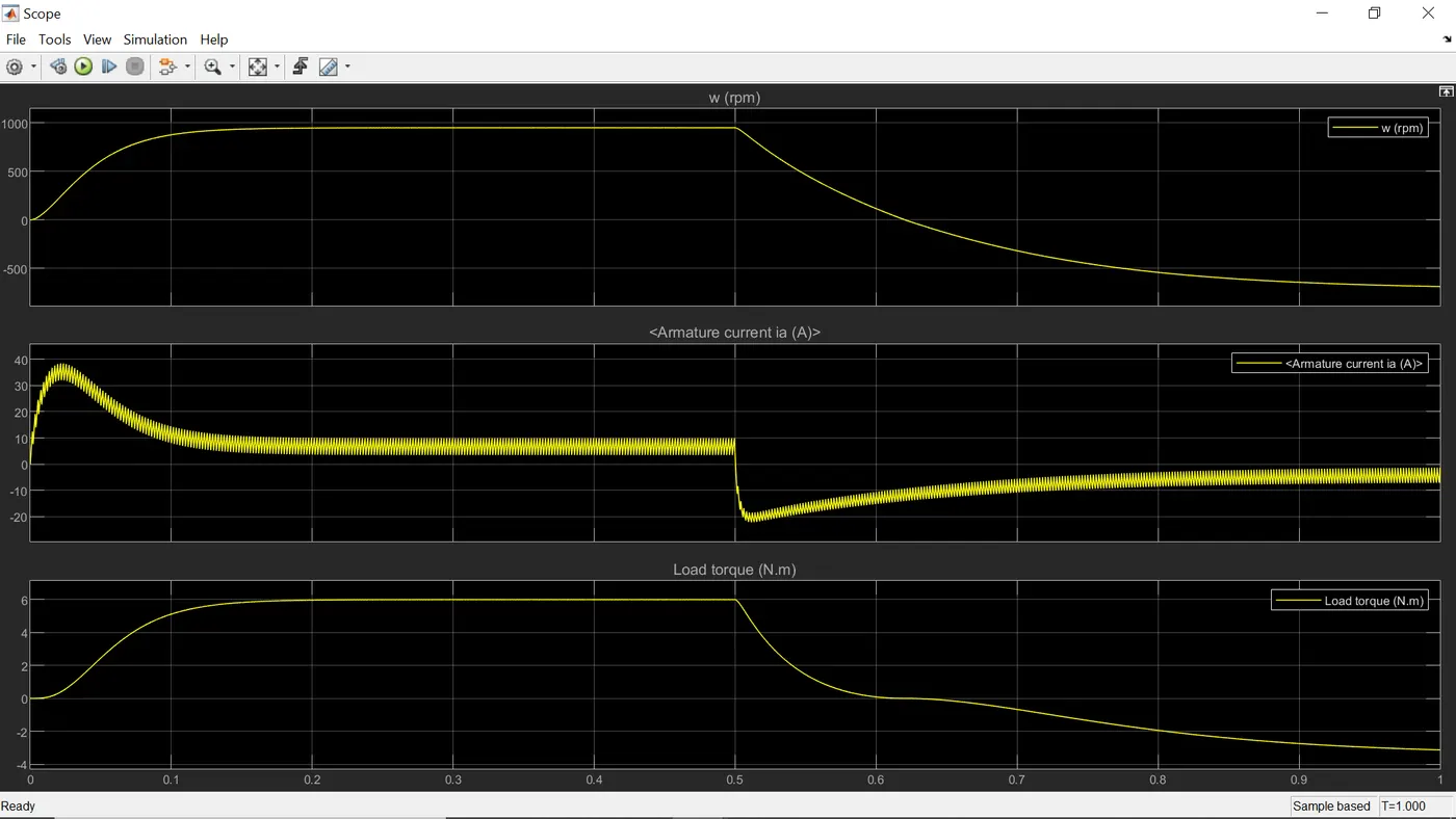
Figure. RPM, Armature Current and Load Torque plots
2. Refer to help section of ‘The Four-Quadrant Chopper DC Drive (DC7) block’. Compare it with H-bridge model.
The four quadrant chopper DC drive as the name suggests can operate in all the four quadrants which are forward motoring, forward braking, reverse motoring and reverse braking. It has a closed loop torque control. It can act as step down chopper in the first quadrant and as step up chopper in the second quadrant. The DC motor is seperately excited by DC field voltage source. The armature voltage is provided by an IGBT converter controlled by two PI regulators. The converter is fed by DC bus obtained by rectification of AC voltage source.
First regulator is a speed regulator followed by current regulator. The speed regulator will take the desired speed as an input and generate a armature current reference signal which will be used by current regulator to obtain the electromagnetic torque needed to achieve the desired speed. The current regulator will then regulate the armature current supplied to the IGBTs by varying the duty ratios.
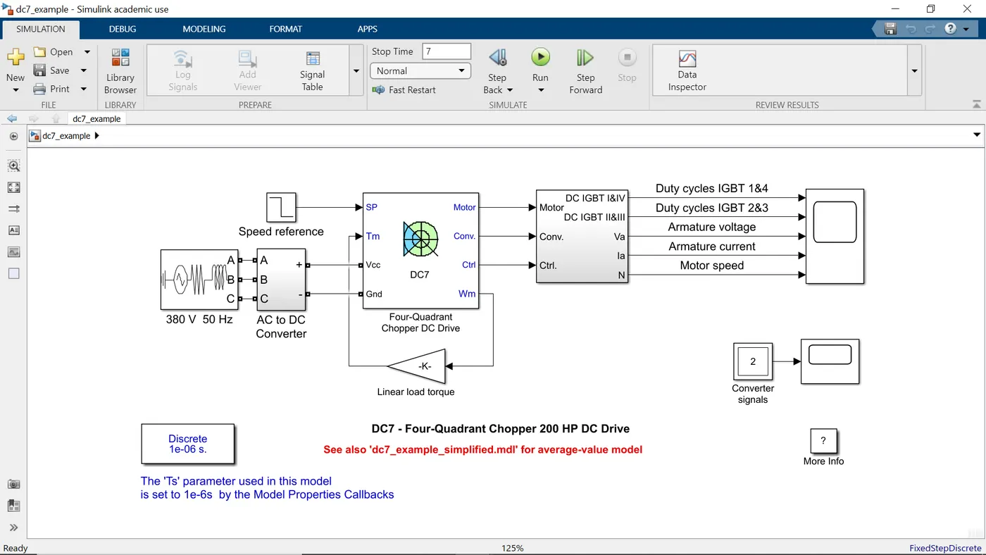 Figure. Four Quadrant Chopper DC Drive
In the above figure we can see that there are 4 inputs: SP (set points), Tm (Torque), Vcc and Gnd. SP is used by speed regulator for identifying the desired speed, Vcc and Gnd are voltage inputs from AC to DC converter. Tm is the torque output generated which is used by feedback loop system to rectify errors between the desired torque and actual torque.
Differences between H bridge and Four quadrant chopper DC drive:
1. H bridge can operate in only two modes forward motoring and reverse motoring but the four quadrant chopper DC drive can operate in all the four quadrants.
2. H bridge is a open loop system and four quadrant chopper DC drive is a close loop system.
3. It is seen that switching losses are higher in four quadrant chopper DC drive than H bridge.
3. Make a suitable EV model using DC7 block and make result report.
The model can be implemented by using the command 'dc7_example' in the command window.
In the model I have used FTP75 drive cycle and the torque speed relation used in `24.7+0.0051omega^2`.
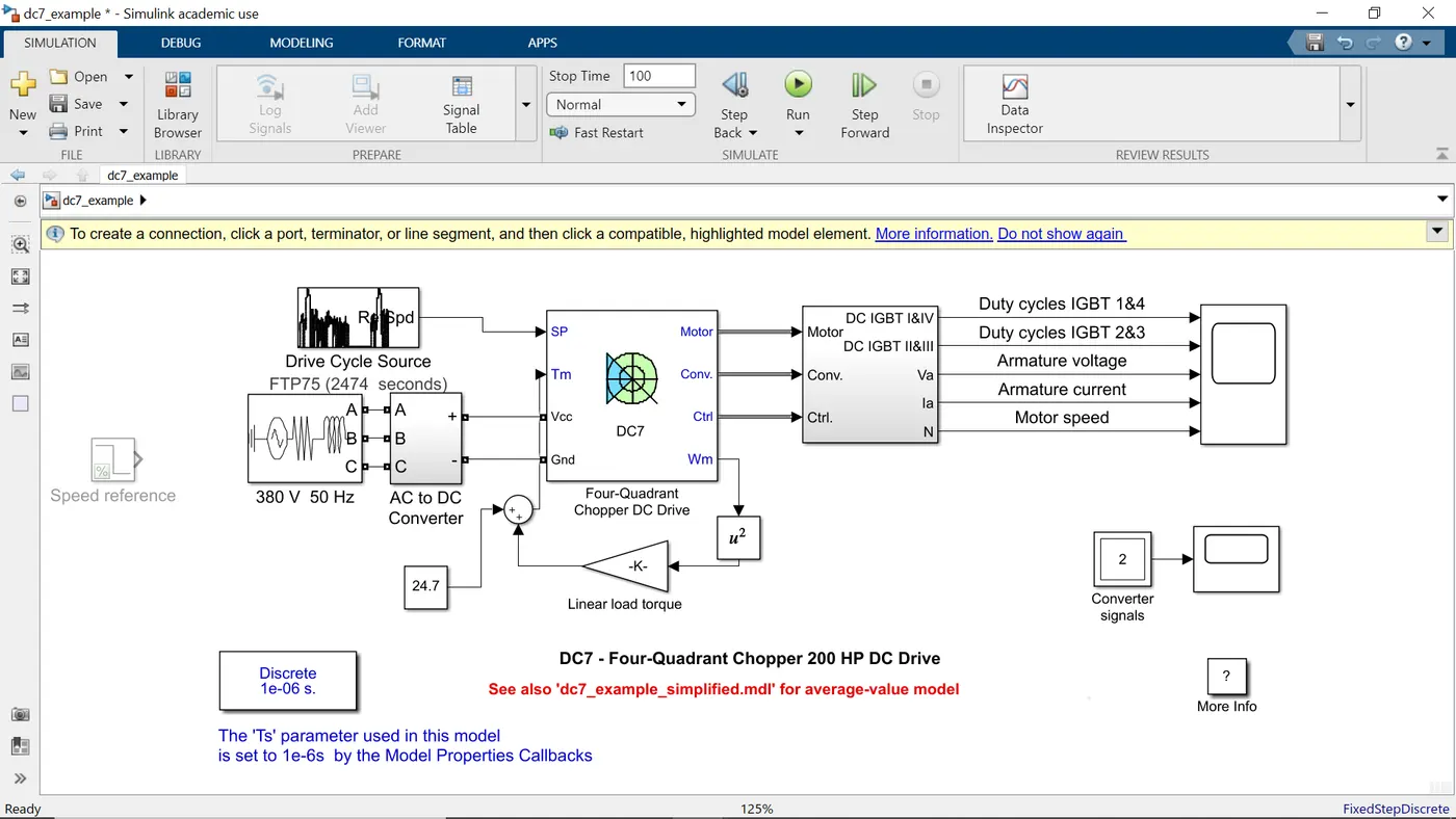
Figure. Four Quadrant Chopper DC Drive Model
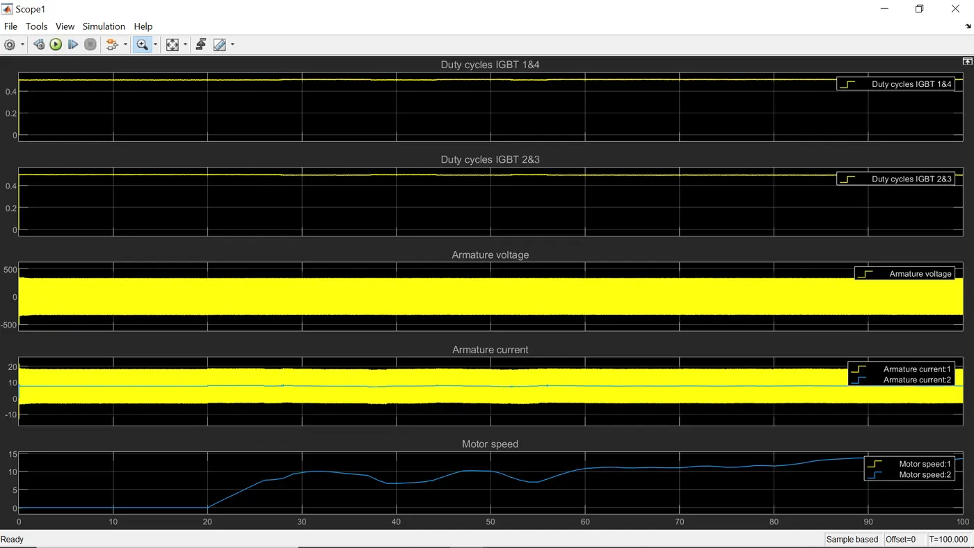
Figure. Results
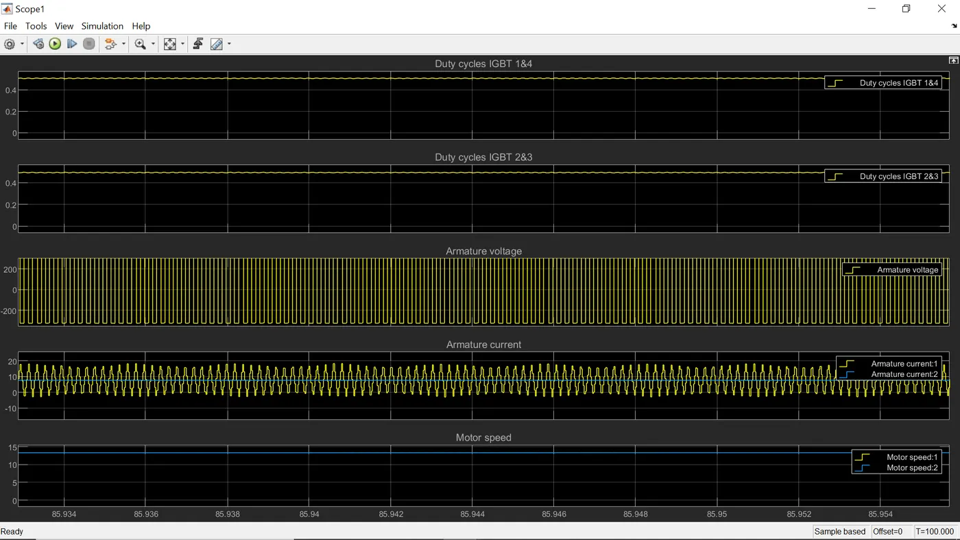
Figure. Closeup Results
The duty cycle for all the IGBTs is around 0.5. The switching frequency seems to be vey high as we can see from the armature voltage and armature current plots. The motor speed gradually increases.