Week-7 Challenge: DC Motor Control
Q1. Run MATLAB demo ‘Speed control of a DC motor using BJT H-bridge’. Modify the model such that armature current doesn’t shoot up when motor changes direction from forward to reverse.
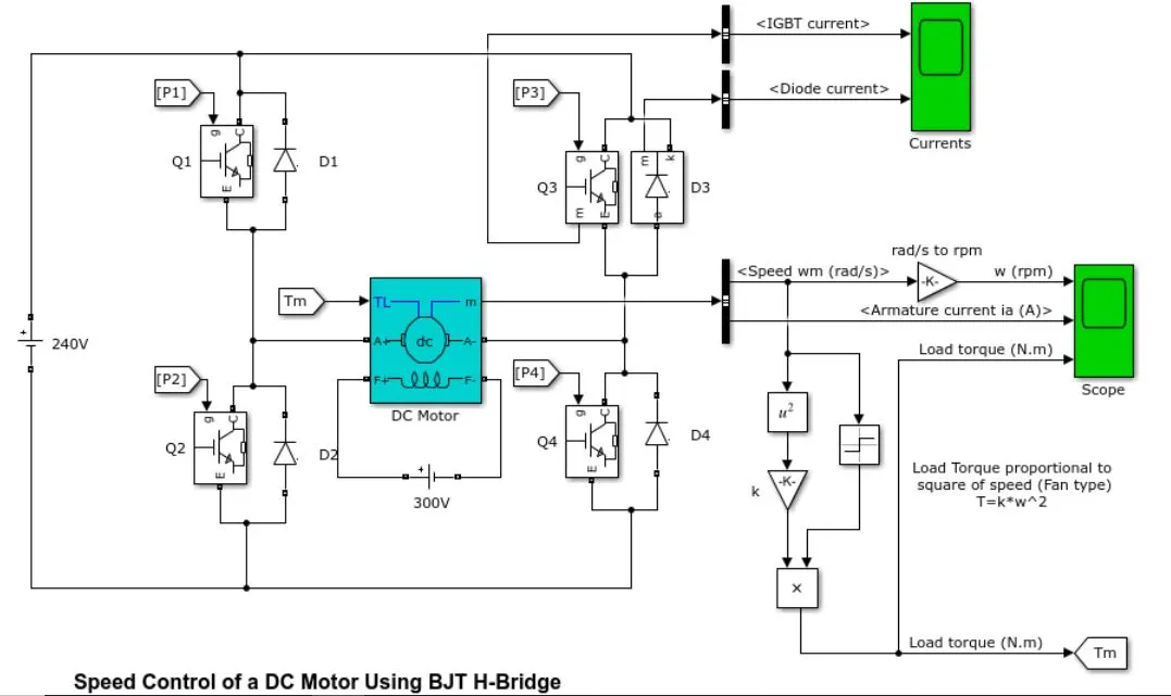
Baseline simulation on the default model blockset: DC Motor speed control using BJT-H bridge
Inputs
- Total cycle time = 1s
- Forward motoring time = 0.5s
- Reverse motoring time = 0.5s
- Battery source voltage = 240V
- Duty cycle = 75%
- Motor supply voltage = Duty cycle * battery voltage = 180V
Results:
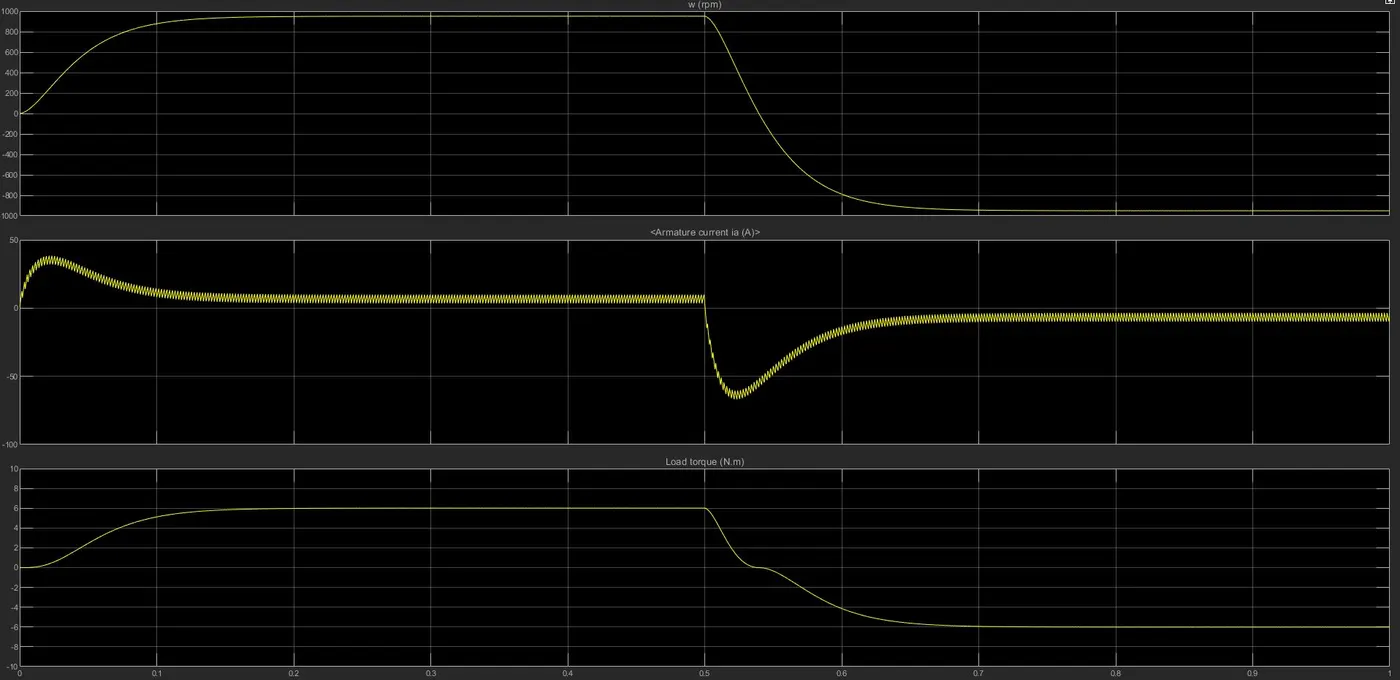
- On the above time the variation of the rpm, armature current and the load torque can be seen for the forward motoring and reverse motoring cycles.
- Max forward speed is 953 rpm between 0 - 0.5 seconds and max reverse speed is -953 rpm between 0.5-1 seconds
- Similarly, the steady state current in forward rotation is 7.83A with an initial spike of 37.5A and steady state current in reverse rotation is -3.4A with a shoot up of -65.1A. This is primarily because DC motors usually require a high starting current to start the rotation. Initially since there is no back emf generated in the conductors the starting current is lower than that needed when reversing the rotation. Additionally the switching losses incurred by power converter also has an effect in increased current spike. This can be controlled by lowering the duty cycle which will be explored in the next simulation.
- The net torque is 6.013 Nm and remains the same across both the rotation cycles.
Simulation 2 - DC motor speed control using BJT-H bridge with 50% duty cycle
Results:
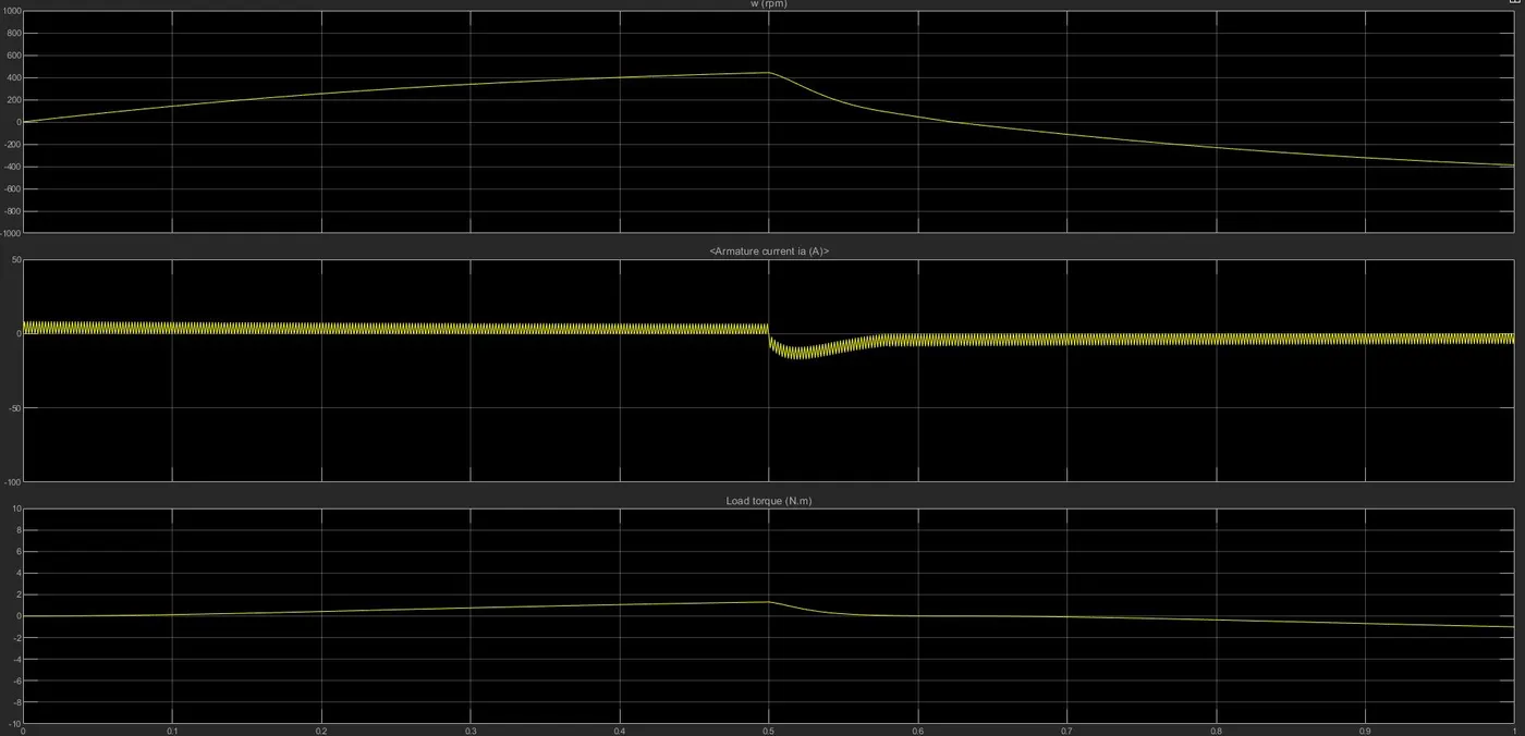
- By reducing the duty cycle, a reduction in the angular speed, armature current and torque can be seen immediately. This is because the supply voltage to the motor has dropped to 120V.
- Corresponding angular speed in forward rotation is 442rpm and in reverse rotation is -380rpm.
- Current in forward rotation = 4.7A and current in reverse rotation = -4.1A.
- Initial start up shoot up current = 7.81A and shoot up when switching rotation is -8.8 A.
Thus by reducing the duty cycle the armature current shoot up spike is reduced.
Q2. Refer to help section of ‘The Four-Quadrant Chopper DC Drive (DC7) block’. Compare it with H-bridge model.
The four quadrant model -
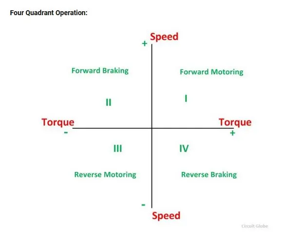
1. I quadrant - power developed is positive and the machine is working as a motor supplying mechanical energy. The I (first) quadrant operation is called Forward Motoring.
2. II quadrant - In this quadrant the direction of rotation is positive, and the torque is negative, and thus, the machine operates as a generator developing a negative torque, which opposes the motion and it is called Forward Braking.
3. III quadrant - The motor works, in the reverse direction. Both the speed and the torque have negative values while the power is positive and it is called Reverse Motoring.
4. IV quadrant - The torque is positive, and the speed is negative. This quadrant corresponds to braking in the reverse and it is called Reverse Braking.
The Four-Quadrant Chopper DC Drive (DC7) block -
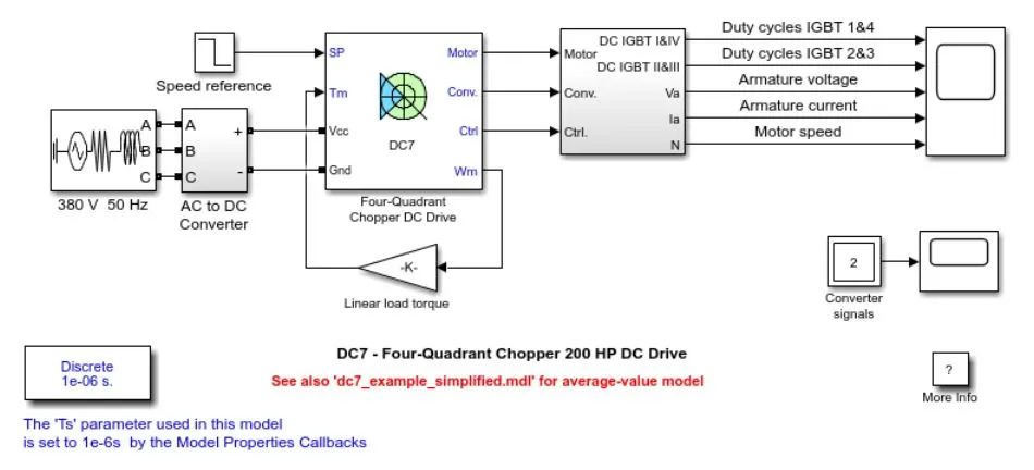
Reference - https://in.mathworks.com/help/physmod/sps/examples/dc7-four-quadrant-chopper-200-hp-dc-drive.html
Simulation parameters:
- Before starting the simulation, set the initial bus voltage to 515 V via the GUI block ('Initial States Setting' button and 'Cbus' variable).
- Start the simulation. You can observe the motor armature voltage and current, the four IGBT pulses and the motor speed on the scope. The current and speed references are also shown.
- The motor is coupled to a linear load, which means that the mechanical torque of the load is proportional to the speed.
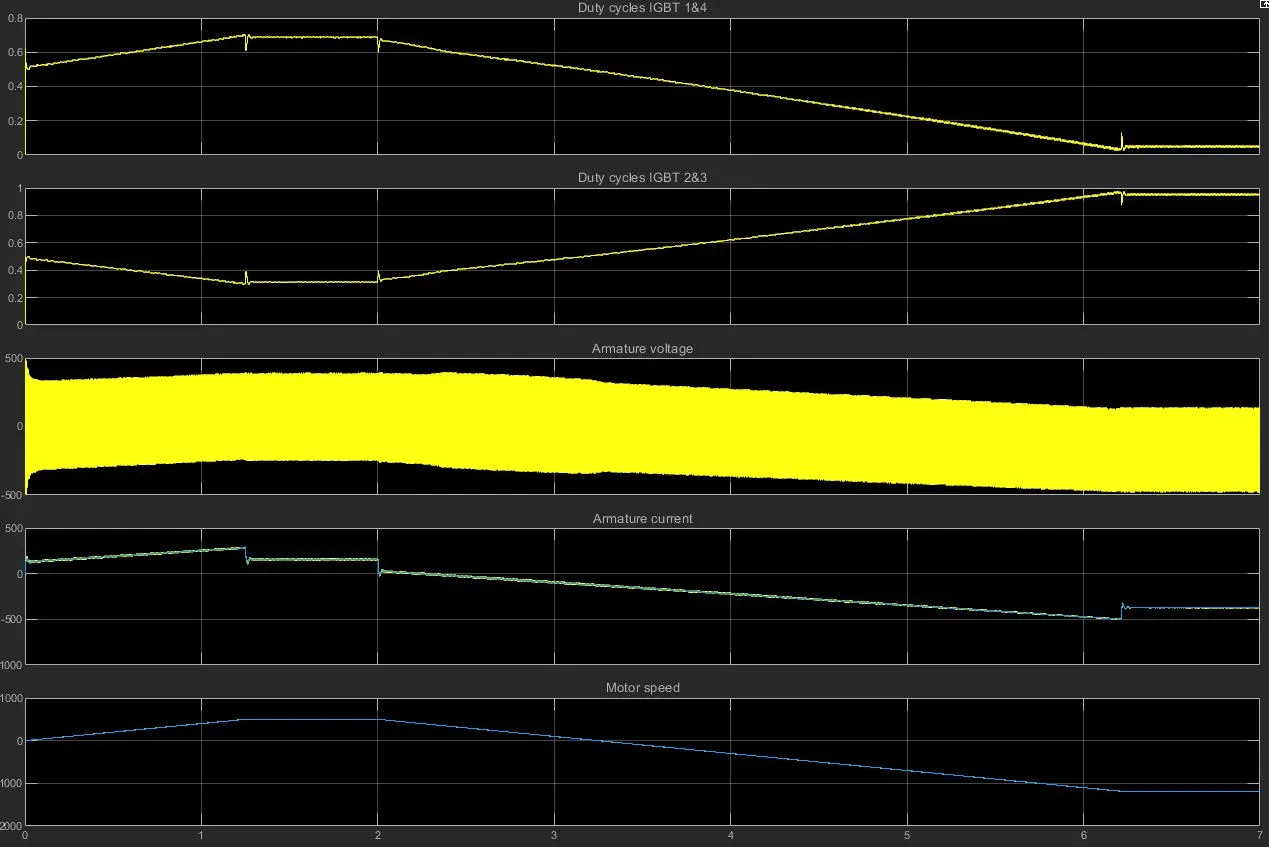
- The speed reference is set at 500 rpm at t = 0 s. Observe that the motor speed follows the reference ramp accurately (+400 rpm/s) and reaches steady state around t = 1.3 s.
- The armature current follows the current reference very well, with fast response time and small ripples. Notice that the current ripple frequency is 5 kHz.
- At t = 2 s, speed reference drops to -1184 rpm. The current reference decreases to reduce the electromagnetic torque and causes the motor to decelerate with the help of the load torque.
- At t = 2.2 s, the current reverses in order to produce a braking electromagnetic torque (dynamic braking mode). This causes the DC bus voltage to increase.
- At t = 3.25 s, the motor reaches 0 rpm and the load torque reverses and becomes negative. The negative current now produces an accelerating electromagnetic torque to allow the motor to follow the negative speed ramp (-400 rpm/s). At t = 6.3 s, the speed reaches -1184 rpm and stabilizes around its reference.
Results:
Comparision between H_bridge and Four Quadrant DC chopper:
1. Control strategy -
- In H-bridge we need to reverse the polarity to change the direction but in Four quadrant DC drive it uses reference speed to change the direction of motor rotation.
- PI Controllers are used for speed and current control in Four quadrant DC drive which is absent in H bridge.
2. Armature current stability -
- The current shootup and disturbances are high in H-Bridge because of the switching losses.
3. Operation -
- Forward and Reverse motoring are the only two operations that the H-Bridge can perform.
- The Four quadrant DC drive operates in four modes forward motoring, reverse motoring,forward braking and reverse braking. Also it can perform regerative braking as well which a H bridge cannot do.
Q3. Make a suitable EV model using DC7 block and make result report.
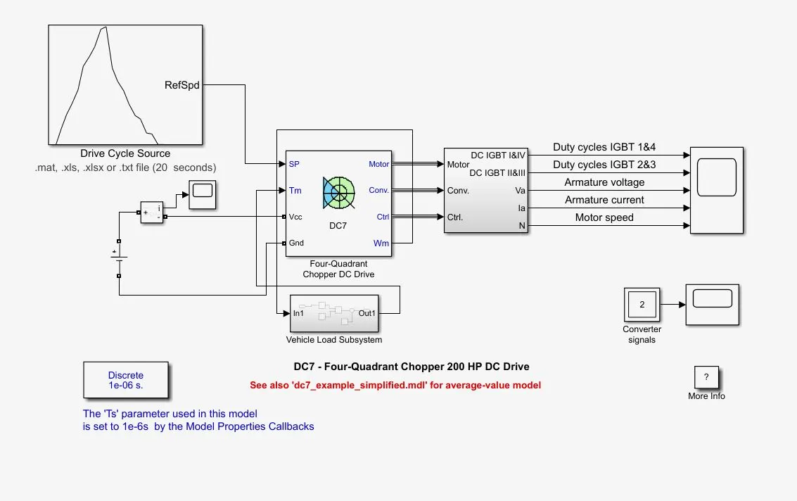
An EV model can be simulated using the DC7 example block with an couple of changes. Lets look at the changes that need to be made.
1. Modify energy source at input side -
Since the battery is source of fuel for an electric vehicle, a DC voltage source block is placed on the input with a supply voltage of 300V.
2. Reference speed -
A drive cycle input needs to replace the step signal block. In this case a custom drivecycle saved in excel file is imported unto a drive cycle block.
3. Linear load torque :
The linear load torque can be replaced by a subsystem model according to the load characteristic given by the equation
T = 24.7 + 0.0051 * (w)^2
where w is the angular speed of the motor.
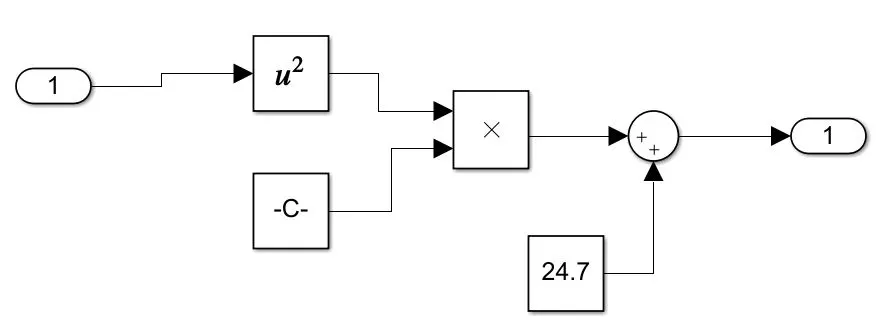
Subsystem of vehicle load characteristics
The final modified DC7 block schematic is shown below.
Results:
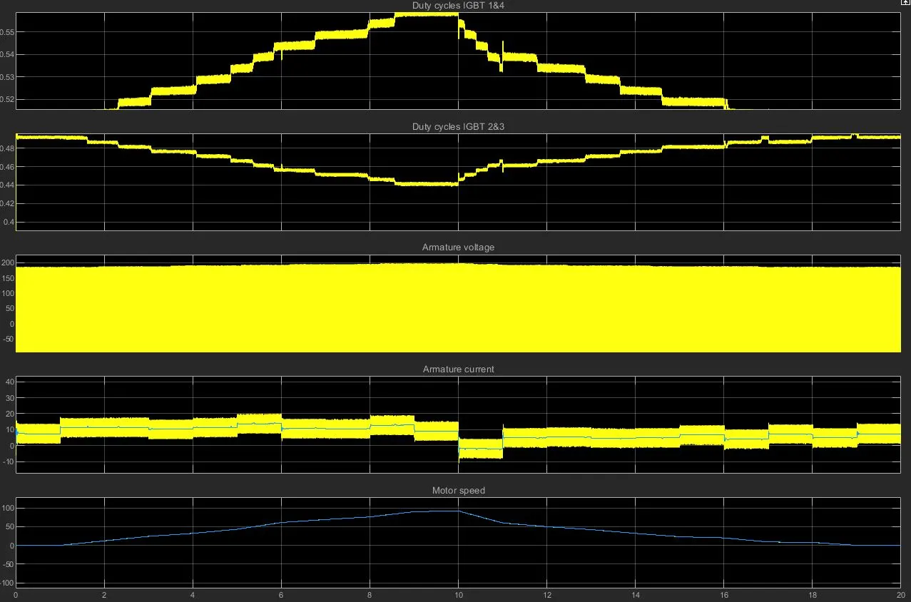
- The speed reference is calculated from the drivecycle range with a time period of 20 secs. The default sampling time of 1e-06s is assumed for this calculation.
- The motor voltages and current, the four IGBT pulses and the motor rpm can be observed on the scope.
- At t=10s, the current is reversed to produce braking electromagnetic torque which causes the DC bus voltage to increase.