Week 7 Challenge - Assembly Workbench
Introduction :
This project involves creating two assemblies from the individual parts and simulate how the individual components interact in a mechanical system. The assembly process showcases the integration and movement between parts using Catia V5 software.
Objective :
The goal of this assignment is to create two assemblies by first designing individual 3D part files from provided 2D diagrams and then assembling them using the Assembly Workbench. After assembly, drafting tools are used to generate 2D drawings similar to the reference drawings provided.
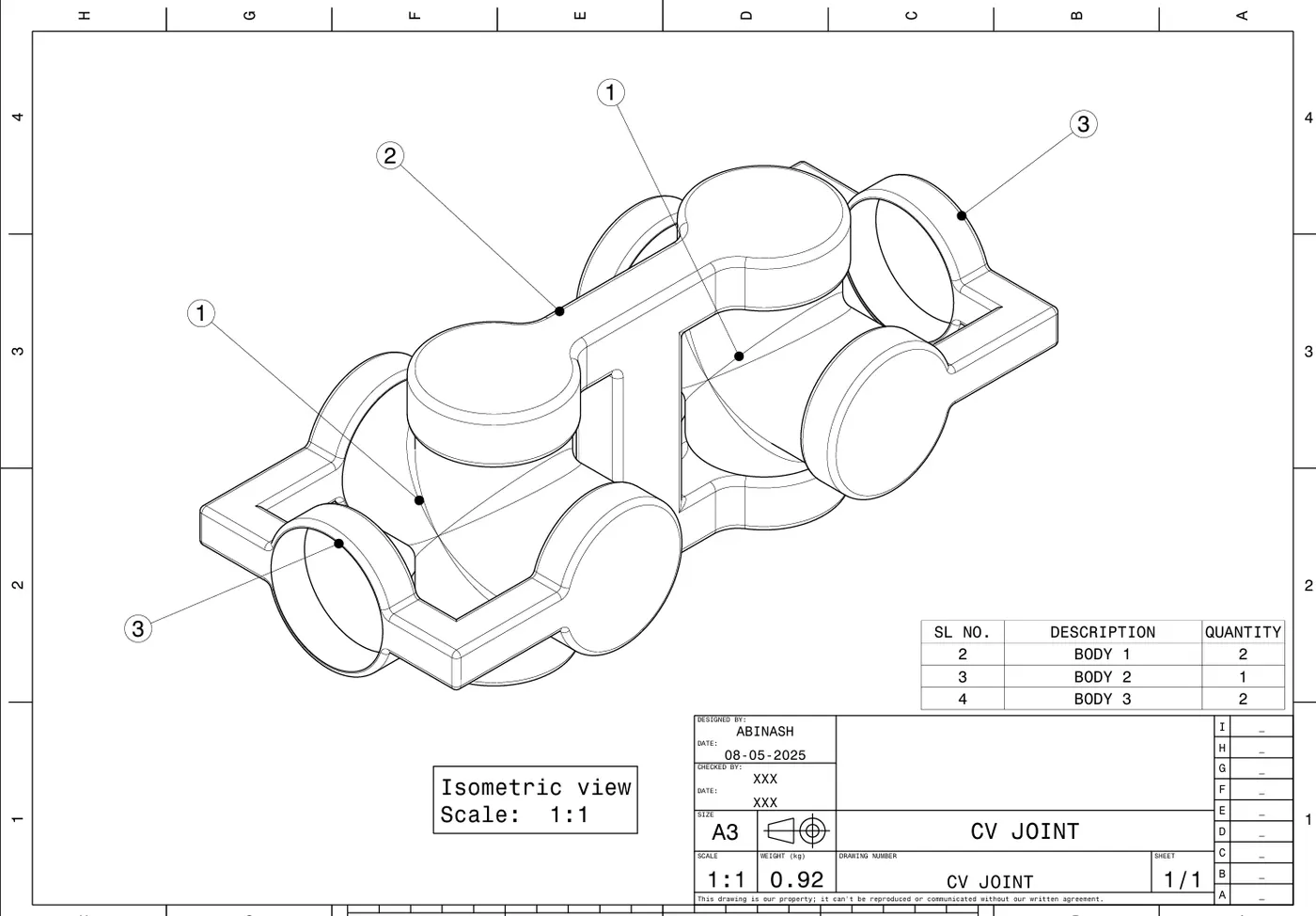
01. CV JOINT
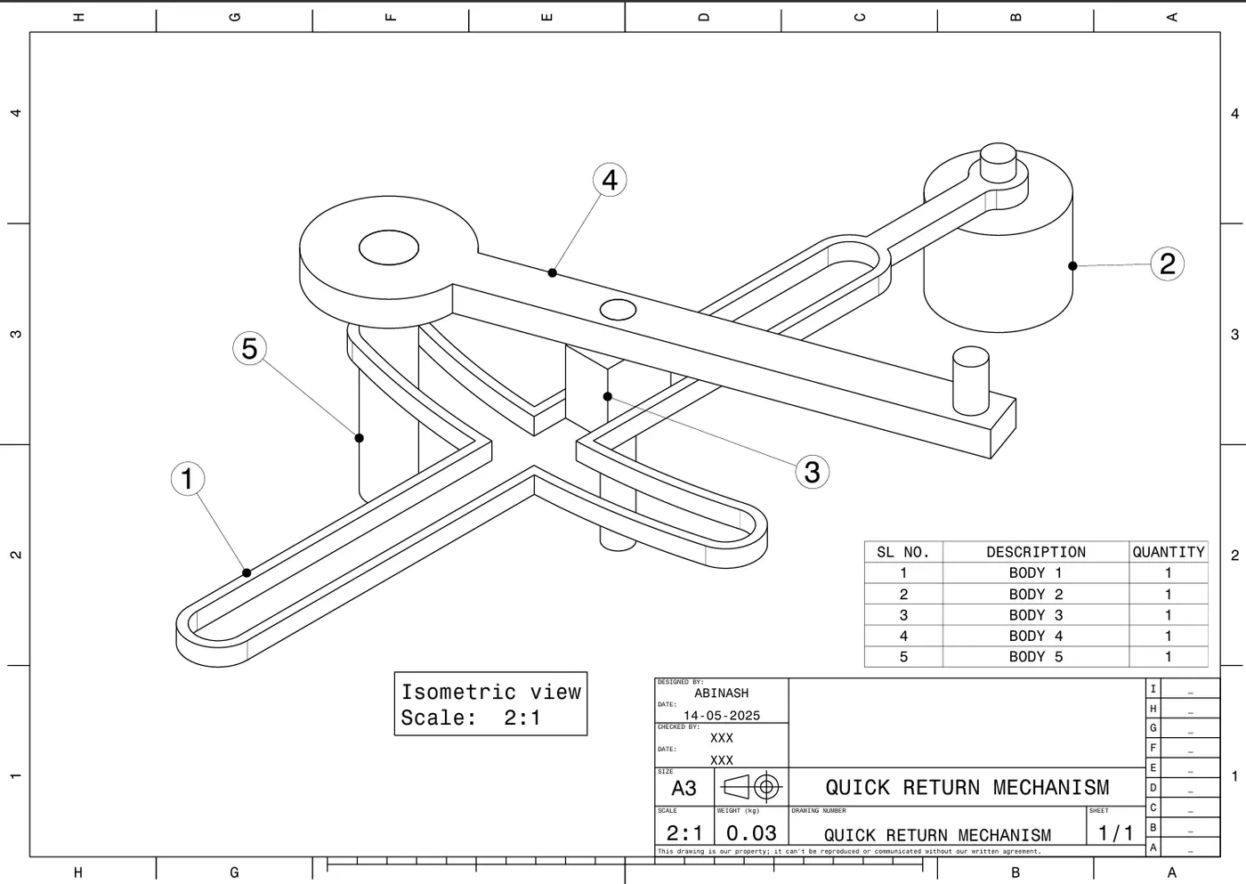
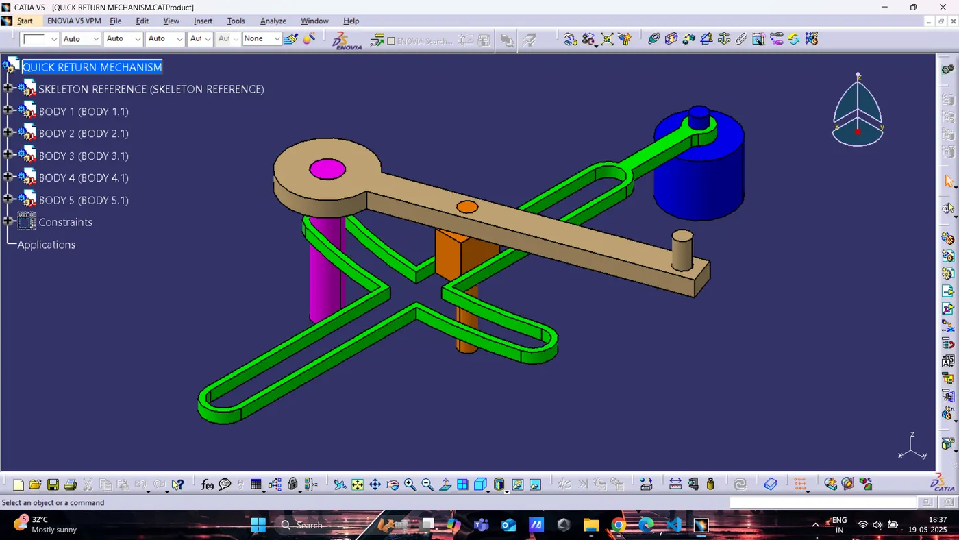
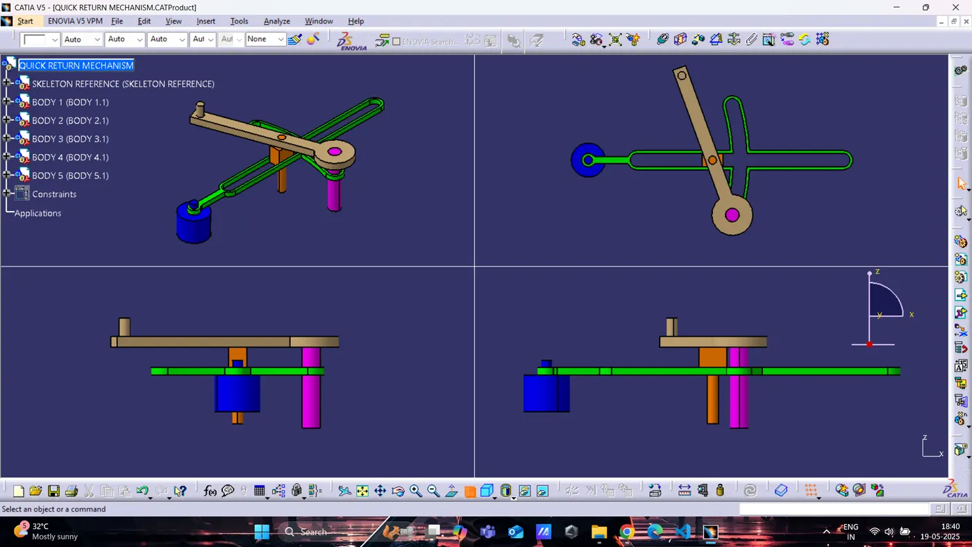
02. QUICK RETURN MECHANISM
Tools and Software Used :
- 3D Modeling Software: Catia V5
- Modules Used:
- Part Design Workbench
- Assembly Workbench
- Drafting Workbench
- Part Design Workbench
- Assembly Workbench
- Drafting Workbench
Part Modeling Process :
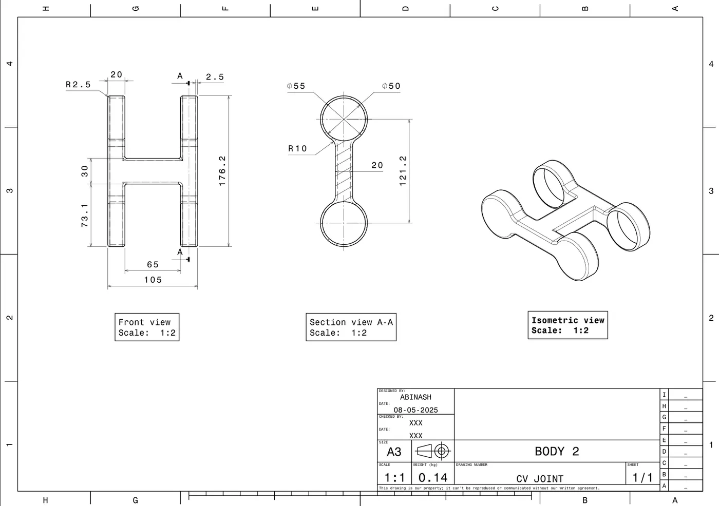
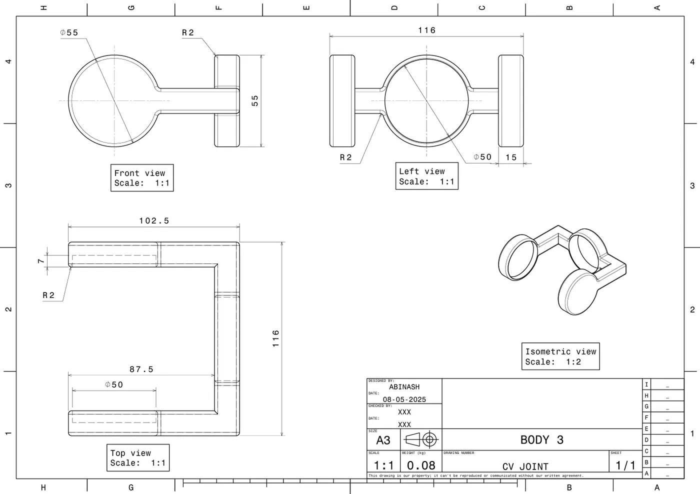
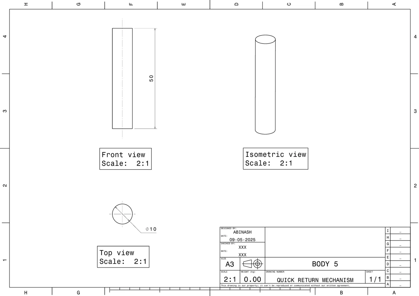
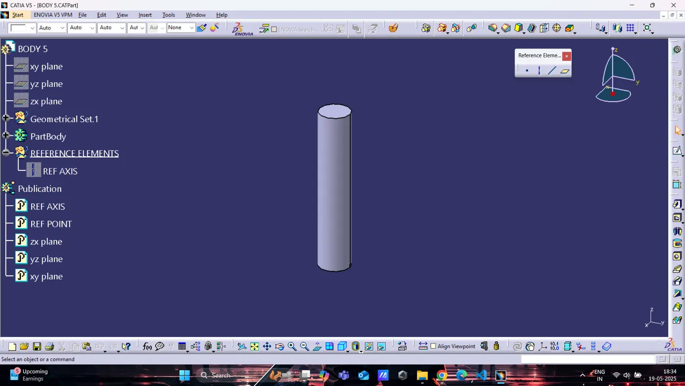
Each part was created using the dimensions and views from the provided 2D drawing.
Tools used: Sketch, Extrude, Pad, Pocket, Fillet, etc.
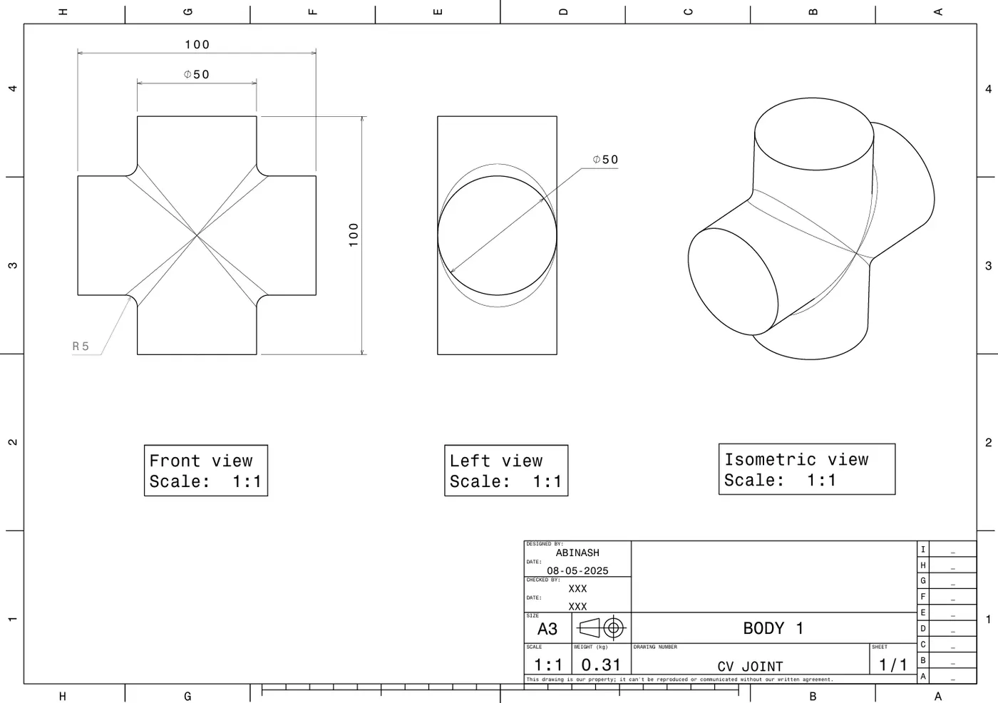
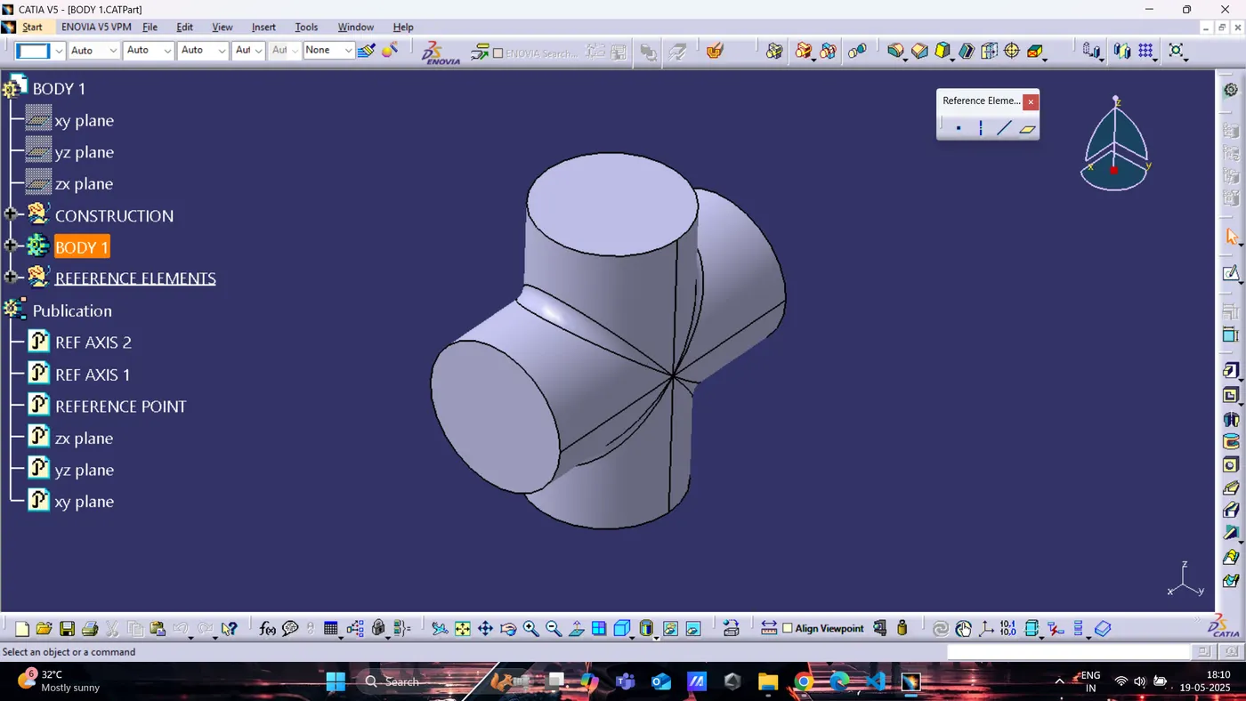
CV JOINT :
BODY 1
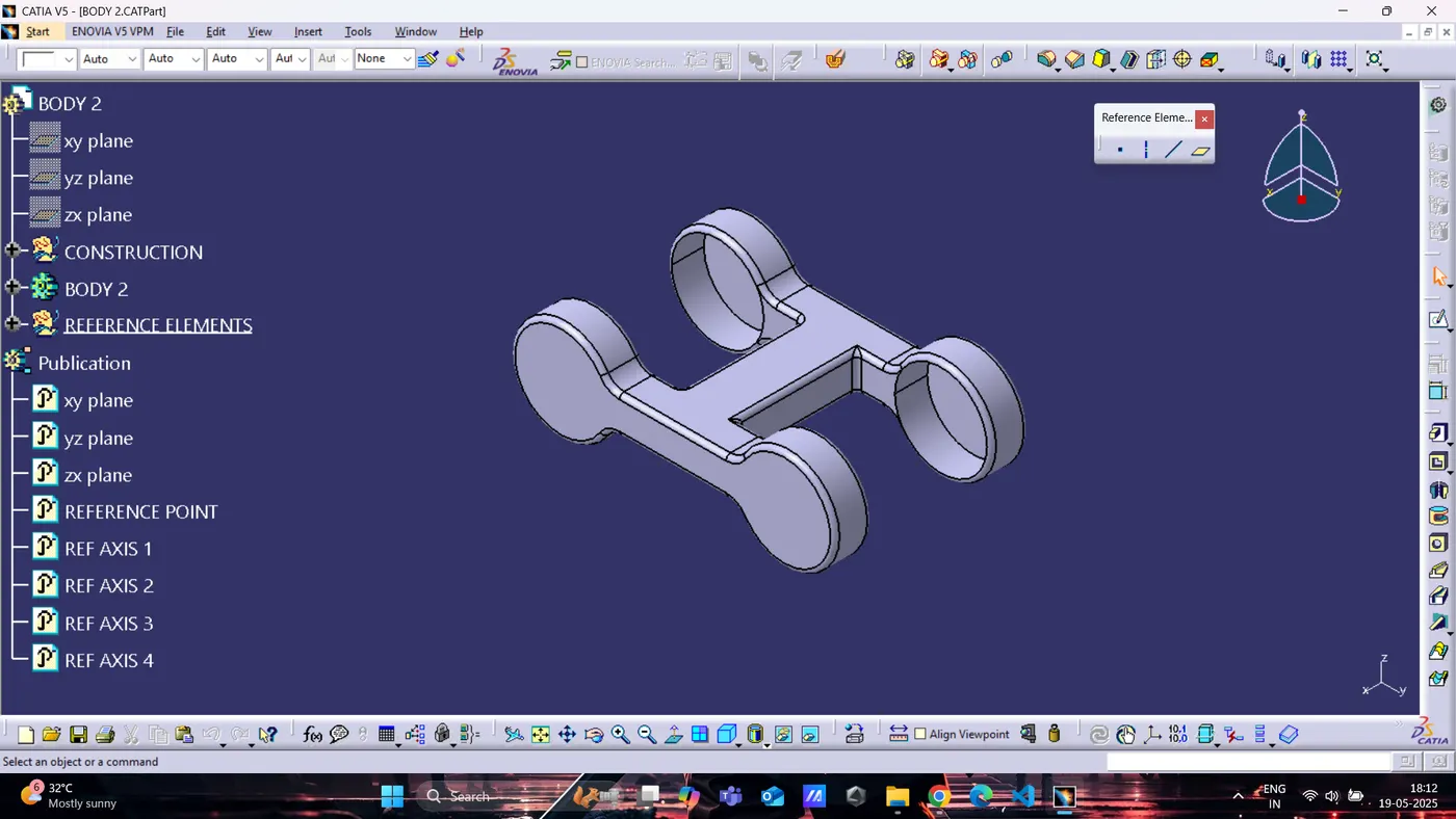
BODY 2
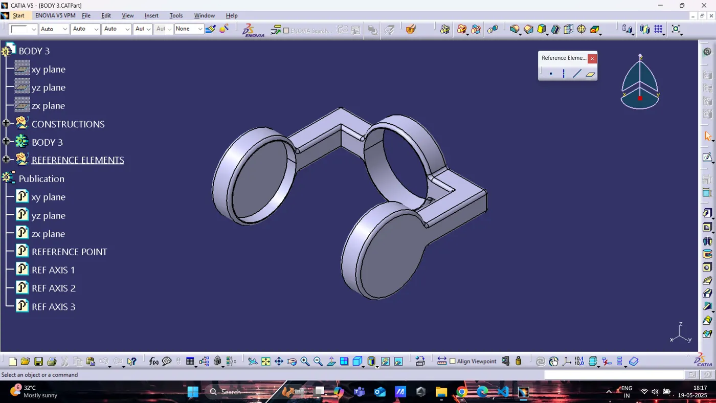
BODY 3
QUICK RETURN MECHANISM :
BODY 1
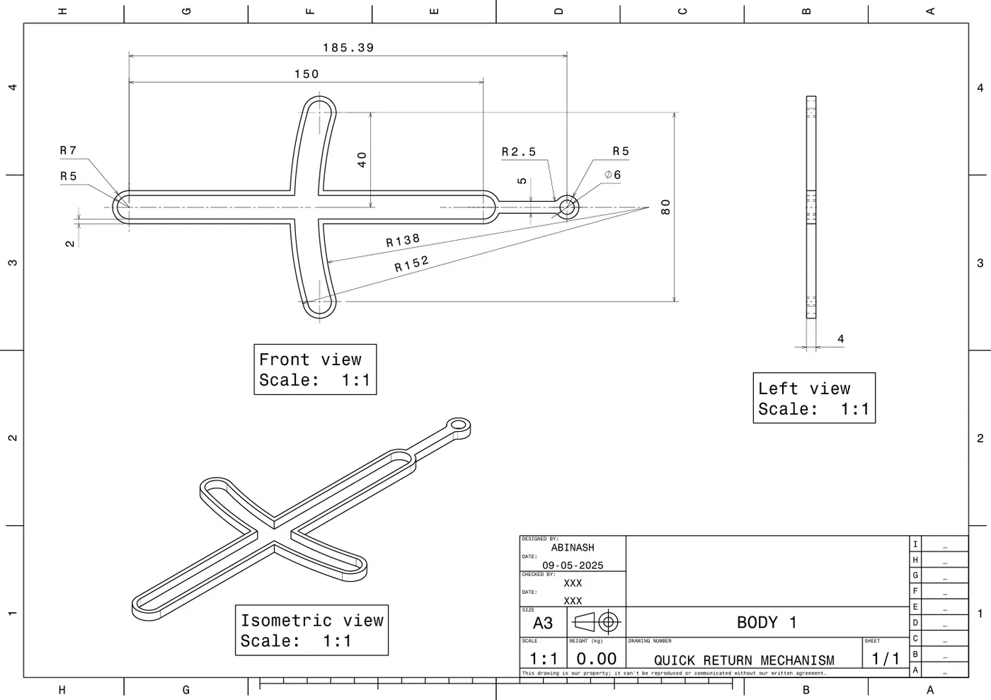
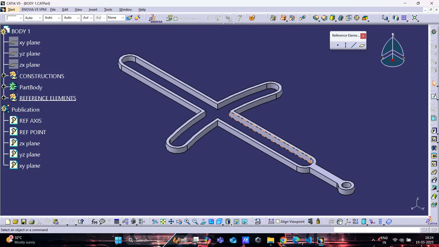
BODY 2
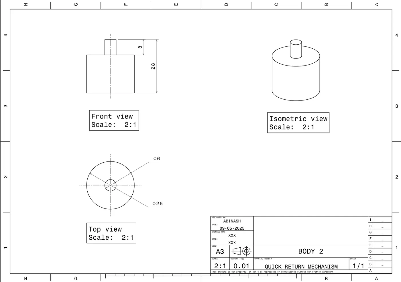
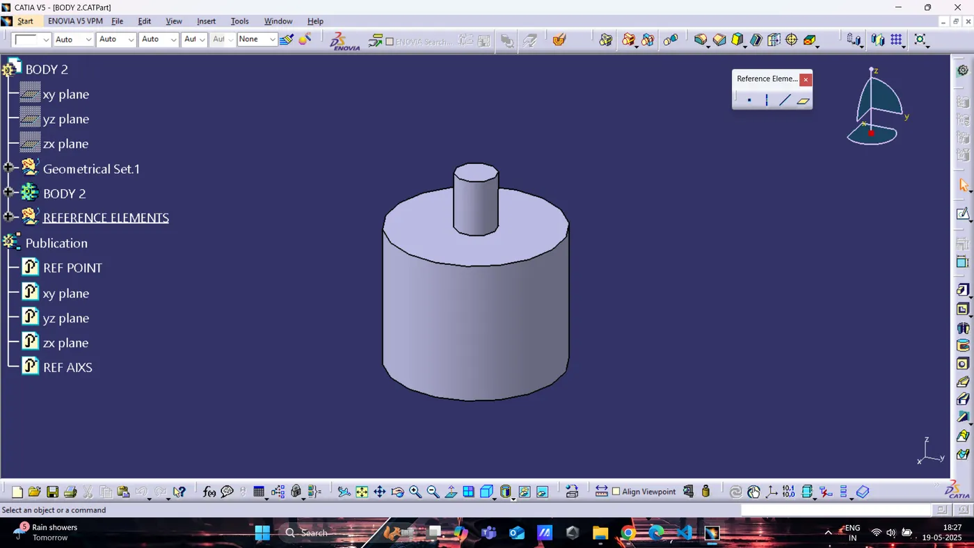
BODY 3
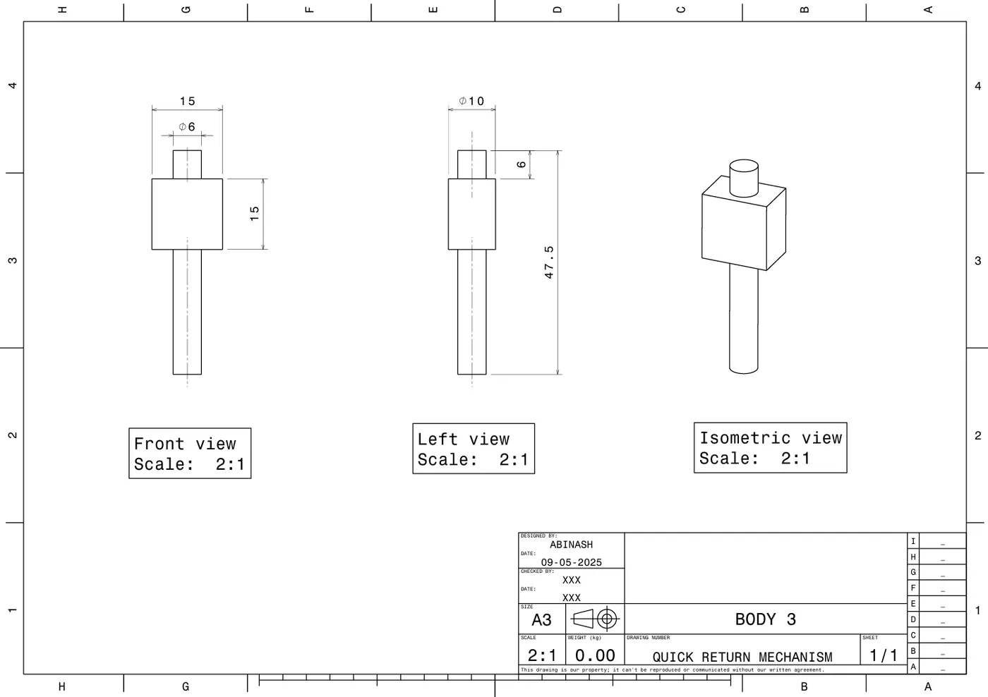
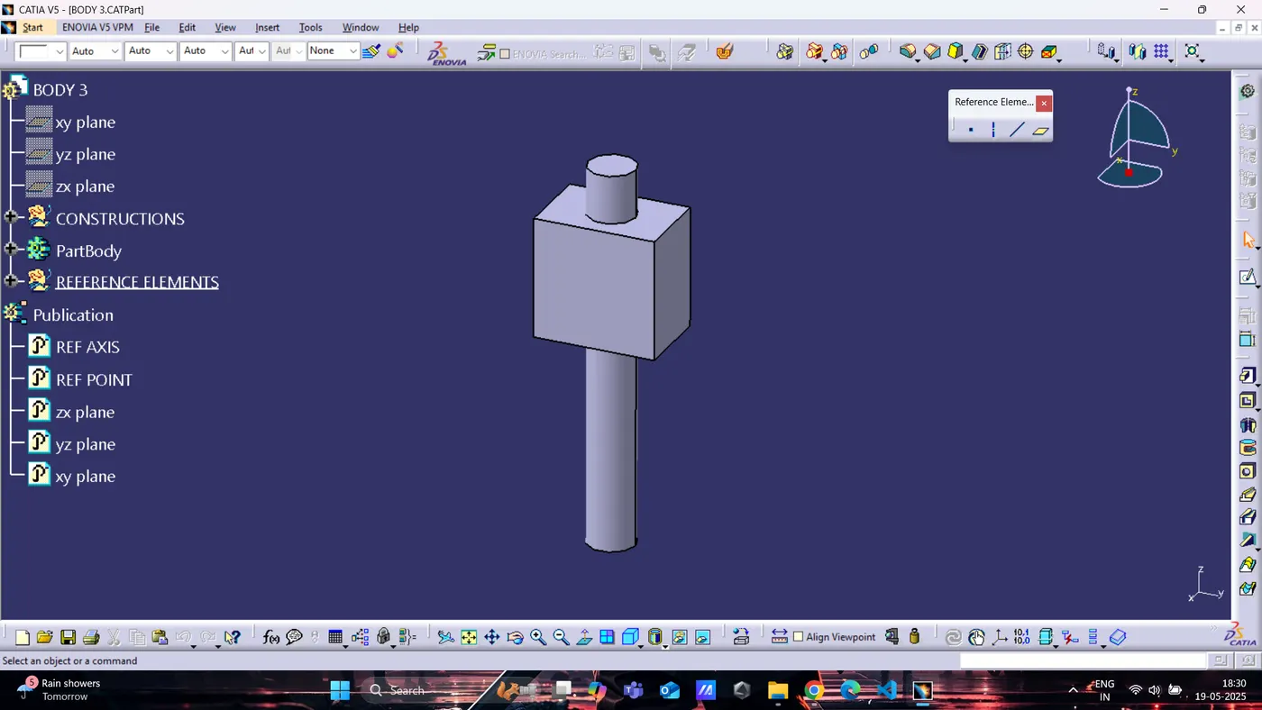
BODY 4
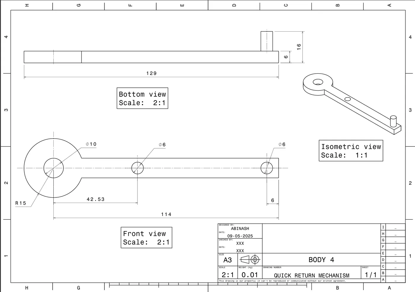
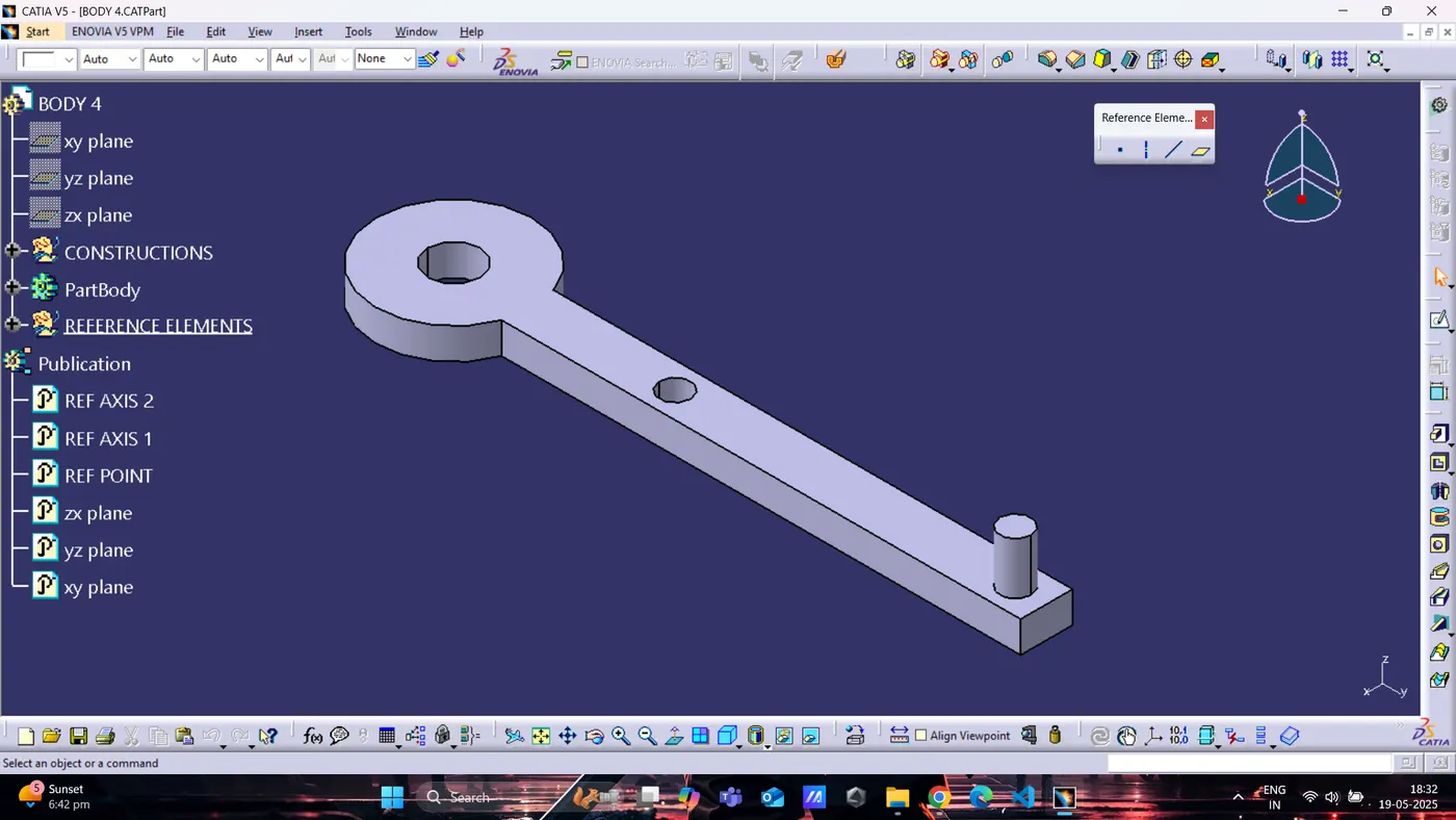
BODY 5
Assembly Creation :
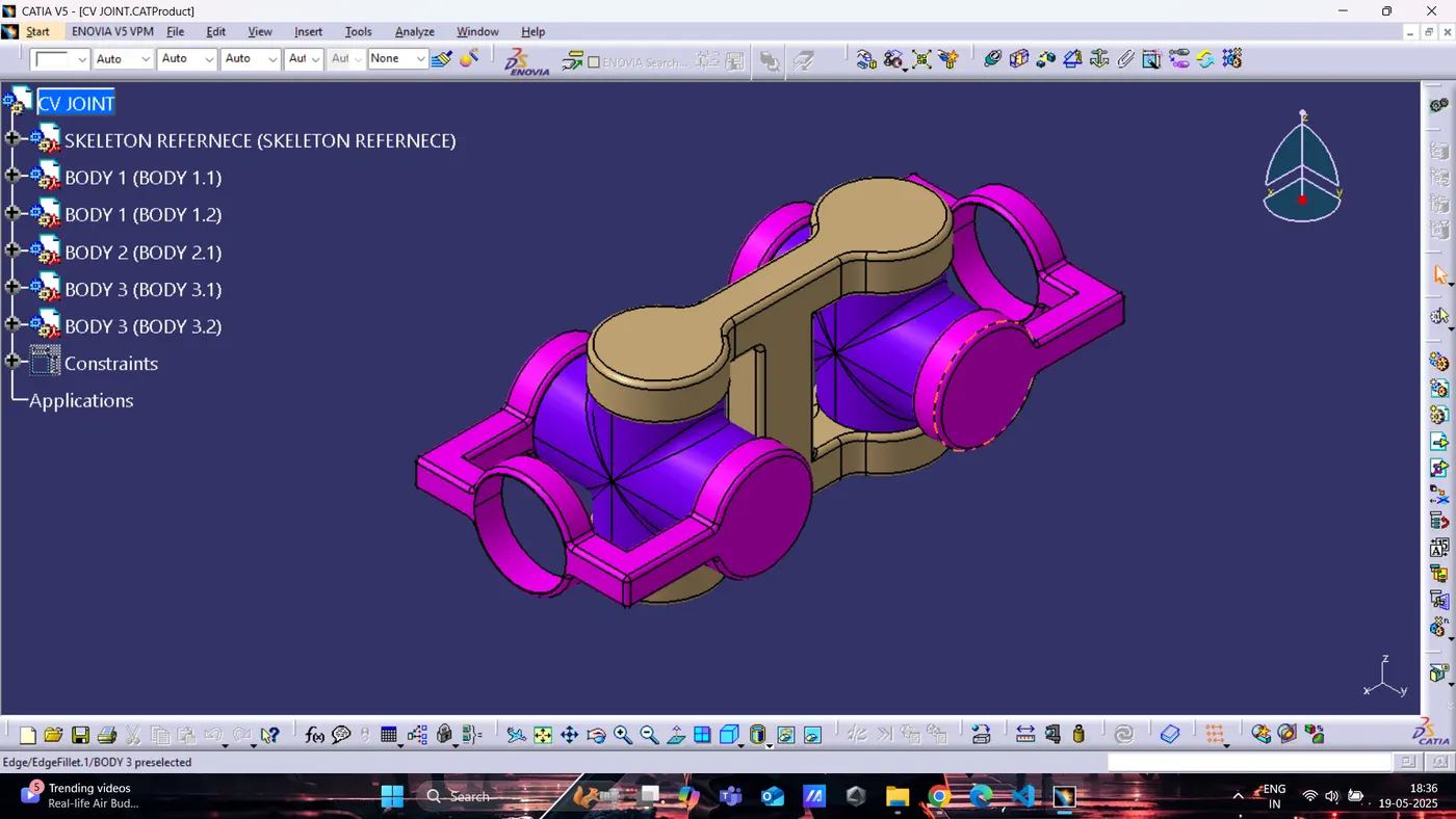
· Switched to the Assembly Workbench.
· Imported all part files for each assembly.
· Applied appropriate constraints:
o Coincidence
o Contact
o Offset / Distance
o Angle
o Fix
· Verified the fit and alignment of parts.
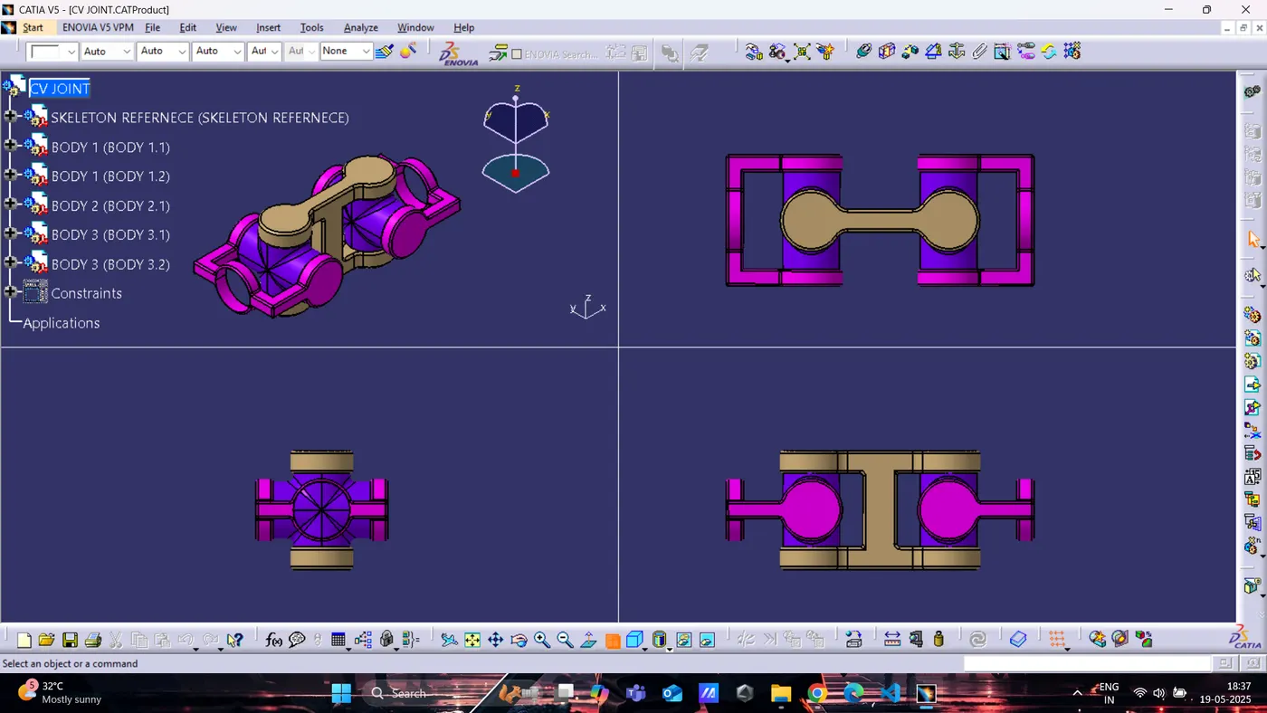
CV JOINT :
QUICK RETURN MECHANISM :
Drafting / 2D Drawing :
· Used the Drafting Workbench to create 2D drawings of each completed assembly.
· Views included: Front View, Side View, Top View & Isometric View
· Added dimensions, part names, title block, and annotations as per the example drawing in the assignment.
Challenges and Learnings :
- Challenges faced:
o Understanding unclear dimensions
o Aligning complex shapes
o Applying correct constraints
- Learnings:
o Converting 2D diagrams to accurate 3D models
o Importance of assembly constraints
o Drafting standards and layout