Week 7- Base Unit Design Challenges 2
Aim :-
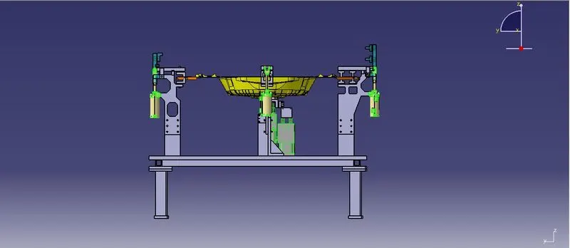
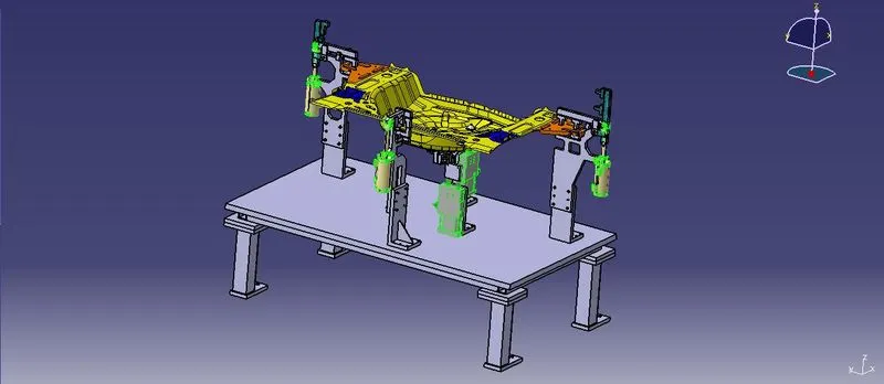
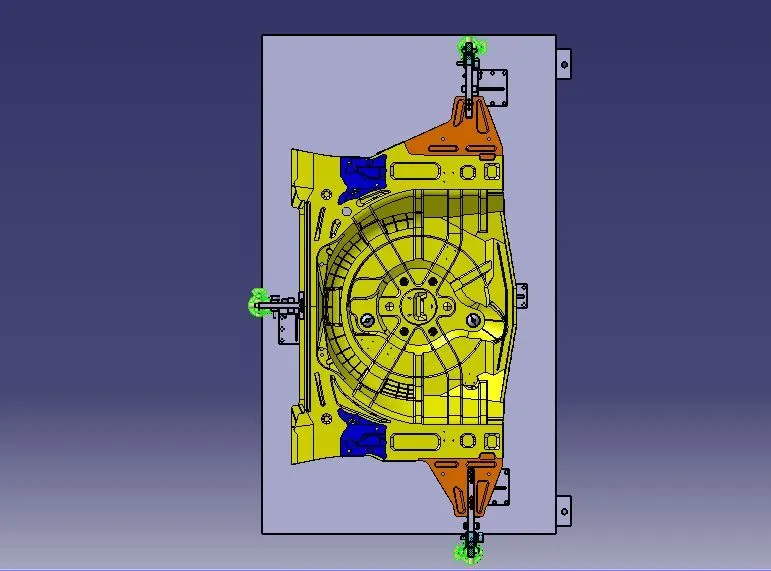
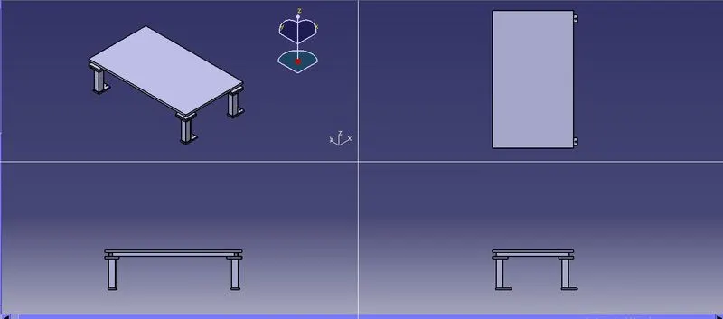
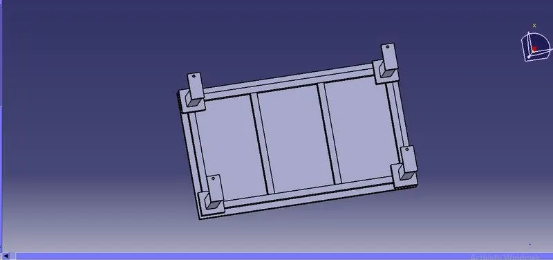
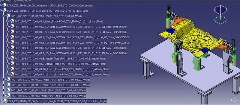
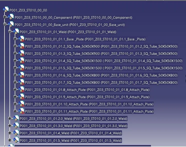
Design a Base Unit for the units designed for the above challenges with all weldments for the given Car Panel.
Introduction :-
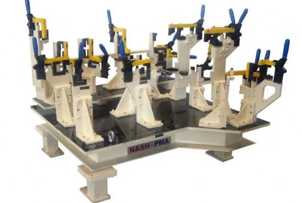
Base Unit : A base unit is the designed to mount all the other units (clamp unit, pin unit , rest unit , etc.)of the tool,also other parts necessary for a tool like pneumatic valve box , trunking cable path will also be mounted on to a base unit. Base unit is the fundamental component of the fixture because all other components are mounted over its so every fixture have base unit .
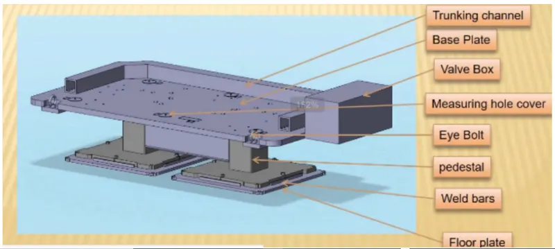
The typical parts of the Base Unit
Base plate:-
- The base plate has no of holes drilled on it which will act as mounting points for clamp unit,pin unit and so on.
Trucking channel :-
- Truking Channel is duct that carries ll the electrical and pneumatic connections (wires and pipes) for units of the tool.
- It has a thickness of few millimeters.
Pedestal :-
- It is used to connect the base plate with a floor plate.
- The pedestal can be standard part or a make part, depending on the size and height of the fixture.
- Standard pedestals are avialable in different inclinations.
- Pedestal are also avilable in different inclinations.
- Depending on the size of the base plate , the number of a pedestal for a fixture can vary for load ditribution.
Valve Box :- valve box is a standard part which contains all the valve for the pneumatic units.The valve box is the box which includes different solenoid valves. The pneumatic fixtures work on air pressure provided to it. So the arrangement of air pressure inlet & outlet is done within this valve box. The trunking channel includes all the pressure inlet cables going to the pneumatic parts of the fixture & protects them from damaging while operation is in process.
Floor Plate :-
- They are also known as foundation plate. They are grounded by using a fixed bolt.
- 10mm clearnace should be give between pedestal base plate and floor plate.
- Weld bars need to use after the levelling is done by levelling srew.
- Welded bars are steel plates along the sides of the base plate of a pedestal.
- Weld bars are used to position the positions permanently.
MEASURING HOLE COVERS:
Measuring Hole covers is on the base unit which is used to cover the datum holes. to safeguadr the datum hioles from damage, covers are used.
• Measuring hole is drilled over the base plate which having exact coordinates so that all other holes can take reference from it.
• The measuring hole number depends on the size of base plate and these holes are covered by using some plates to protect against from dust damage etc.
EYEBOLTS:
Eye bolts are used for the transporting of the tool using lift hooks,Fork Lift holes will also be provided in some cases for transporting purpose.
• It is to drag the entire unit and relocated.
• Eye bolts are the bolts that are used to lift the fixture for transportation by inserting hooks into them.
WELD BARS:
Weld bars are used to mount the base plate to the floor.
FLOOR PLATE:
They are also known as foundation plate.They are grounded by using a fixed bolt 10mm clearance should be given between pedestal base plate and floor plate.
• Weld bars need to use after the levelling is done by levelling screw.
• Weld bars are steel plates along the sides of the base plate of a pedestal.
• Weld bars are used to position the positions permanently.
POINTS SHOULD BE TAKEN WHILE DESIGNING A BASE UNIT
• A base plate size should cover all the units with its outer periphery inclusding opening.
• A base plate is preferred to be designed with respect to BCS coordinates.
• Working height depends on the nature of the manual or robotic welding fixture and for manual fixture we need to consider the working height be 850 - 1100mm and its depending upon the working height of the worker or its about ergonomics.lt differs by countries.
• A base plate should be drilled with datum holes/measuring holes in line with a pitch of 1000mm in general.
• Number of datum holes is depend on the size of the base plate.
• Depending upon the Weight of the fixture design unit we need to select the eyebolt size for lifting the base plate.while shifting the fixture units from one place to another they will not damage or damaging any other units.
• Datum holes should be drilled at nominal values of coordinates,and in terms of 50 and 100 in general.
• Example - X=100,Y=-600,Z=250
• Depending upon the component size and weight of the total units you can decide whether you need a fabricated base or a plate.Mostly fabricated bases are used and made of square or a rectangle tube with the plate.
• Datum holes should be drilled with dia 100 mm away from outer units.
• Datum holes should be covered with cover plates.
• The base Unit of the fixture must be strong enough so that deflection of the fixture is as mimum as possible during welding,This Deflection is caused by the forces of welding and while clamping of the panel.
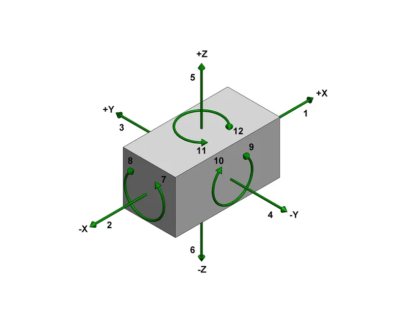
The 3-2-1 principle of location (six point location principle) is used to constrain the movement of work-piece along the three axes XX,YY, and ZZ. This is achieved by proving six locating points. 3 pins in the base plate, 2 pin in verticle plane and 1 pin in a plane which is perpendicular to the first two planes.
- (3) Minimum three locator blocks to establish part plane. Three locators or supports are placed under the work piece. The three locators are usually positioned on the primary surface. This restricts one axial movement downwards and four radial movements together the three locators restrict five degrees of freedom.
- (2) Round locating pin in a round hole that defines location in four direction ( 4- way) perpendicular to the plane previously established. This restricts four axial movements.
- (1)Round locating pin in a slot that defines two of the direction of the other pin (2-way). This restricts two axial movements.
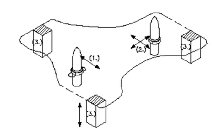
Degree of freedom controlled by 3-2-1 location principle.