Week 7- Base Unit Design Challenges 2
AIM
1) To design a Base Unit for the units designed for the above challenges with all weldments for the given Car Panel.
2) To design the complete Fixture assembly (the units designed in the previous challenges can also be used). Make sure that all the 5 Panels given in the CAD data are fully constrained with the 3-2-1 principle.
BASE UNIT
- Base unit is the unit of fixture which is designed as such so that other units of the fixture can be mounted on it.
- Apart from these units, other necessary tools like pneumatic valve box, trunking cable path will also be mounted on the base unit.
- Base unit is the fundamental component of the fixture because all other components are mounted over it and so every fixture has base unit.
- The base unit design is different according to the panel, Design of clamp system, location system.
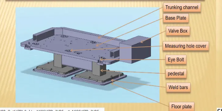
PARTS OF THE BASE UNIT
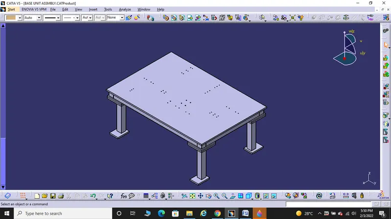
BASE PLATE
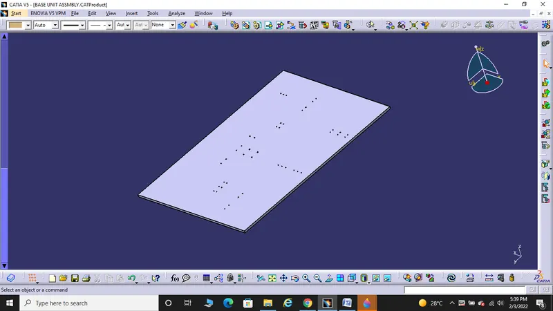
- Base plate is a plate of 25mm to 40mm thickness.
- Base plate has no of holes drilled on it which will act as mounting points for clamp unit, pin unit and so on.
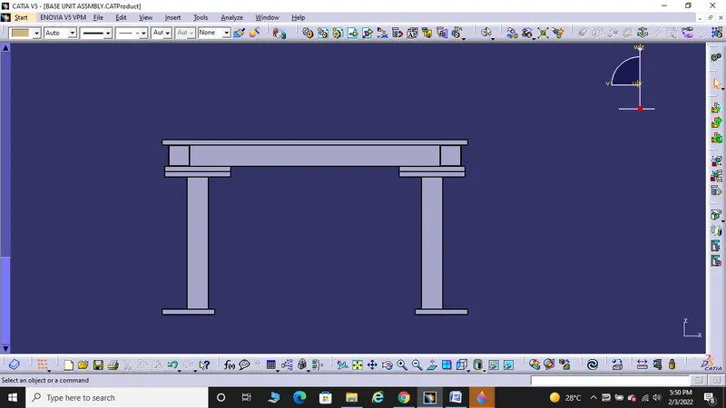
PEDESTAL
- It is used to connect the base plate with a floor plate.
- The pedestal can be a standard part or a make part, depending on the size and height of the fixture.
- Standard pedestals are available in different inclinations.
- Depending on the size of the base plate, the number of pedestal for a fixture can vary for load distribution.
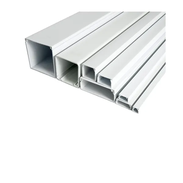
TRUNKING CHANNEL
- Trunking channel is a duct that carries all the electrical and pneumatic connections (wires and pipes) for units of the tool.
- It has a thickness of few millimeters.
EYEBOLTS
- Eye bolts are the bolts that are used to lift the fixture for transportation by inserting hooks into them.
- For example, we usually use M20 bolts that are bolted on the base plate.
- Used for transportation pupose, sometimes forklift holes will be provided.
FLOOR PLATE
- They are also known as foundation plate.
- They are grounded by using a fixed bolt.
- 10mm clearance should be given between pedestal base plate and floor plate.
- Weld bars need to use after the leveling is done by leveling screw.
- Weld bars are used to position the positions permanently.
VALVE BOX
- Valve box is a standard part which contains all the valves for the pneumatic units.
- The valve box is the box which includes different solenoid valves.
- The pneumatic fixture works on air pressure provided to it. So the arrangement of air pressure inlet & outlet is done within this valve box.
- The trunking channel includes all the pressure inlet cables going to the pneumatic parts of the fixture & protects them from damaging while operation is in process.
PROCEUDRE OF DESIGNING A BASE UNIT
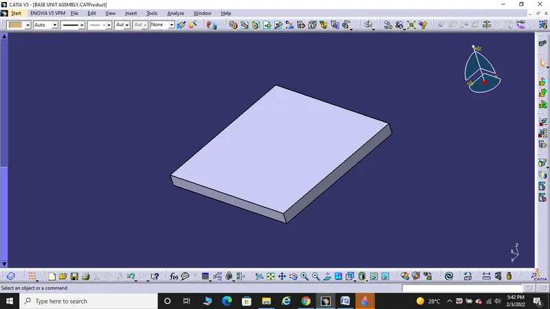
- Initially base plate is created with design considerations and with respect to the panel.
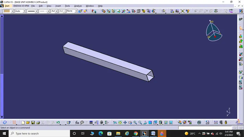
- Then a Square tube type truning channel is created.
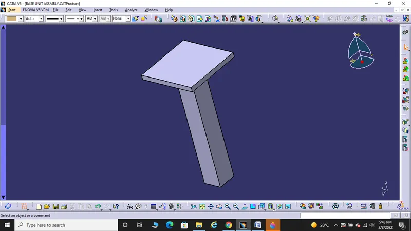
- After designing truning channel, Plate is designed with thickness of 20mm to provide leg structure to the base unit assembly.
- Leg structure is designed as per design considerations in all the corners of the base unit.
FUNDAMENTS OF BASE PLATE DESIGN
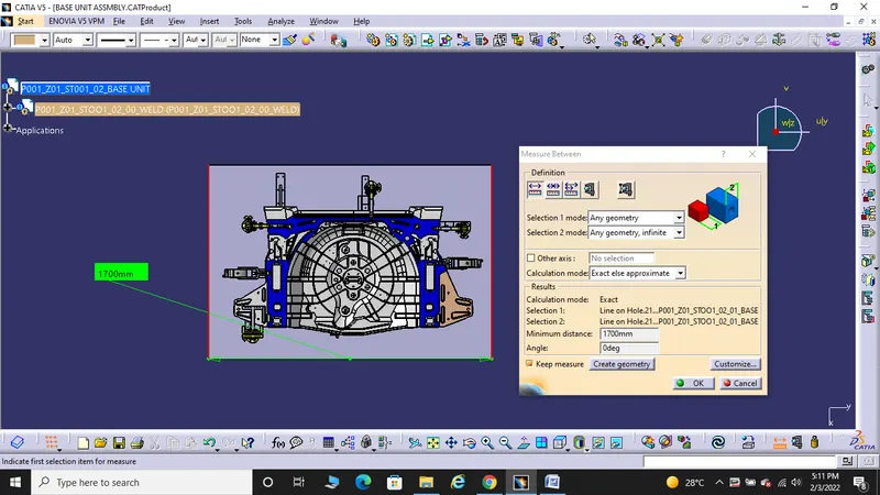
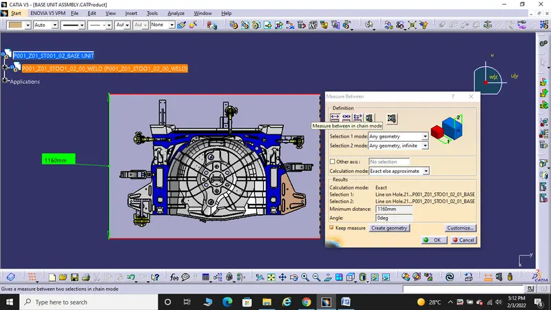
- A base plate should cover all the units with its outer periphery including opening.
- It is to be designed with respect to BCS coordinates.
- Base plate should be drilled with datum holes/ measuring holes in line with a pitch of 100mm in general.
- Number of datum holes depends on the size of the base plate.
- Datum holes should be drilled at nominal values of coordinates and in terms of 50 and 100 and in diameter of 100mm away from other units.
- Datum holes should be covered with cover plates.
DESIGN CONSIDERATIONS OF BASE PLATE
WORKING HEIGHT
- It depends on the nature of the manual or robotic welding fixture.
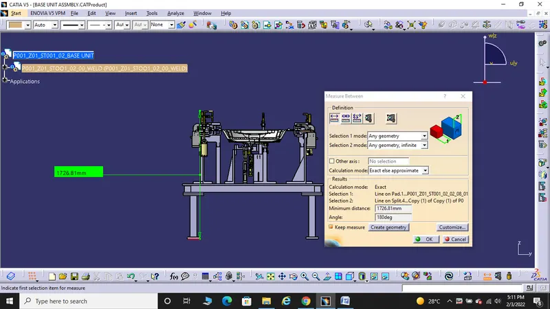
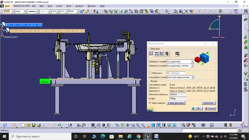
- For manual fixture we need to consider the working height 850-1100mm, depending upon the working height of the worker standard of a specific country will apply (in few countries human height is higher or lower e.g. US, Japan).
- If the base structure is made with a base plate having tubular structure welded below it we can reach to height 100mm – 25mm.
- In this case to reach the working welding height we need to provide additional some leg structure which may have top and plate welded to the tube.
BASE PLATE OR WELDED STRUCTURE
- Depending upon the component size and weight of the total units we can decide whether we need fabricated base or just plate.
- Mostly fabricated bases are used made of square or rectangular tube with plate.
- Base unit of the fixture must be strong enough so that deflection of the fixture is as minimum as possible.
- This deflection of the fixture is caused because of forces of welding clamping on the workpiece.
- The base plate is 20mm in thickness, which is machined the parallelism which can easily sustain a load of units without defelctions.
- The base unit of the fixture should have the mass to prevent vibration and the designed base unit weight 65kg which is good enough to prevent vibration and chatter.
- The base unit should be parallel to the floor to adjust this there should be the provision of height adjusting.
- The height adjusting mechanism is provided to maintain the parallelity of the floor .
- At the time of adjustment, we can provide spacers in order to maintain the parallelism of the floor.
BASE UNIT AND FIXTURE ASSEMBLY
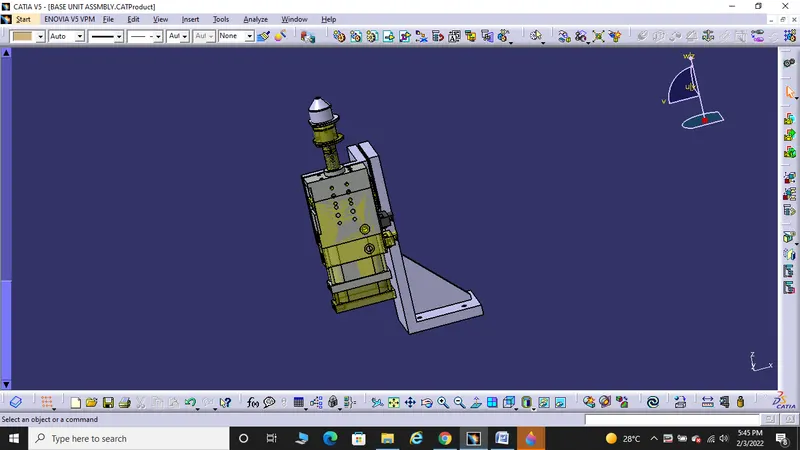
RETRACTABLE PIN UNIT
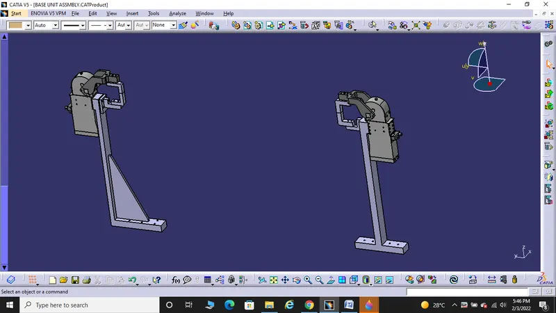
CLAMP UNITS
REST UNITS
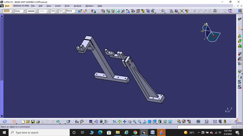
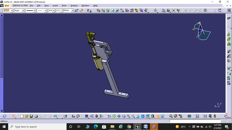
SWIVEL CLAMP UNIT
BASE PLATE
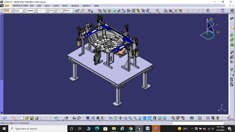
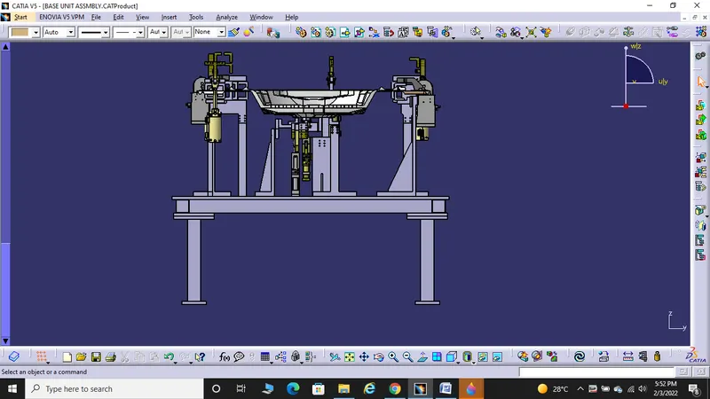
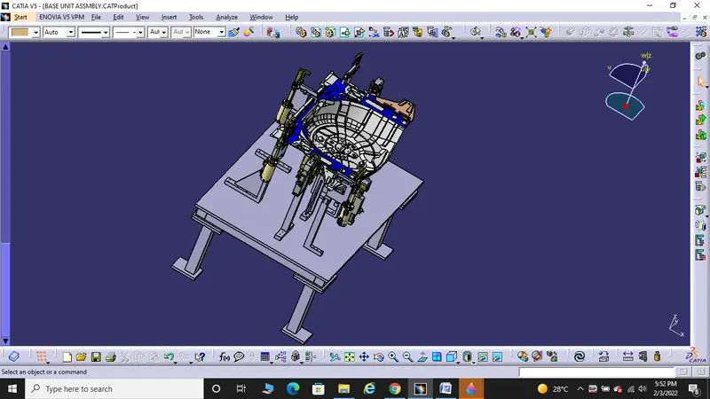
BASE UNIT ASSEMBLY
BASE UNIT WITH FIXTURE ASSEMBLY
CONCLUSION
Thus the designing of a base unit with all weldments for the given car panel and designing of all the other remaining units required for fixture assembly has been complelted.