Week 6-Meshing of Hood Challenge
Mid-surface extraction and meshing of hood
Objective: To extract the mid surface from the given automotive hood, mesh it with a target element size of 5mm and check for the quality criteria given below:
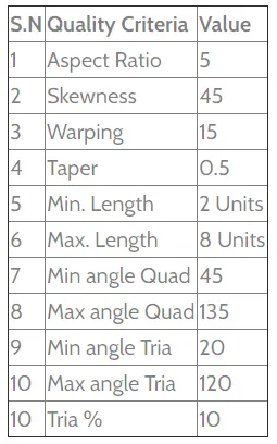
Fig1: Required mesh quality criteria
Geometry: The component under consideration is an automotive hod. It has 5 major parts associated with it - the outer panel, inner panel, a pair of hinges and a latch. All parts are 0.75mm thick.
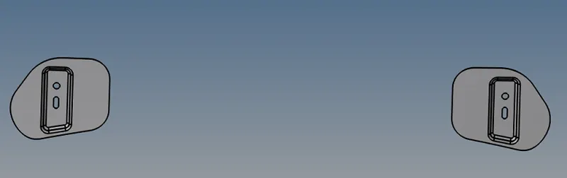
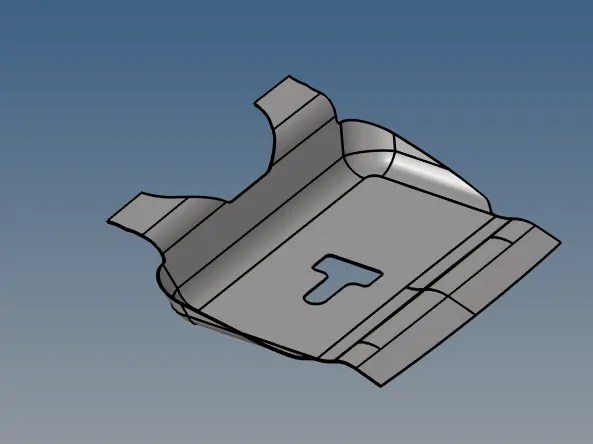
Hinges Latch
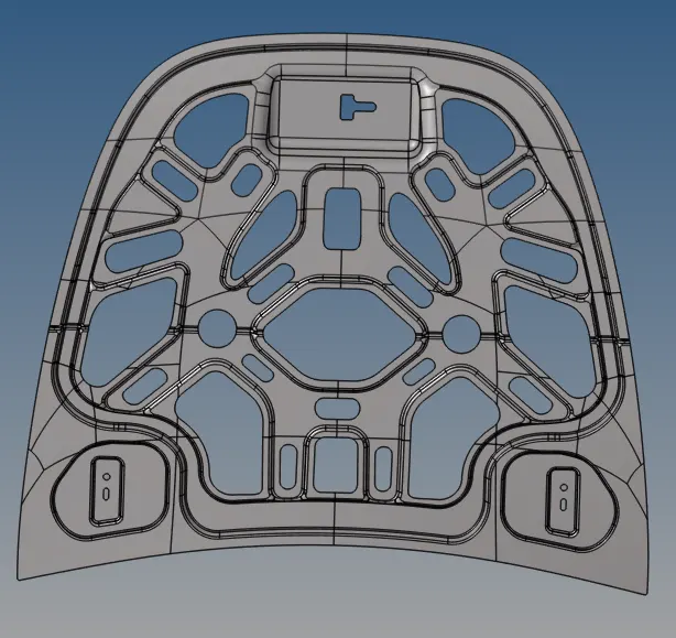
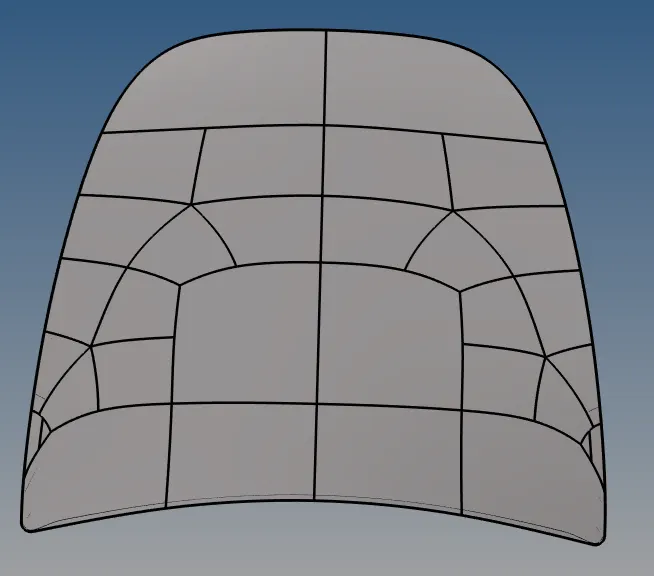
Inner Panel Outer Panel
Mid-surface Extraction: The mid-surface of all parts were extracted using Geom>midsurface>automidsurface. For all the parts, except the inner panel, the default auto extract option settings work and give a good surface geometry. For the inner panel, certain filleted surfaces had to be deleted and recreated using 2D>spline option. Relevant lines had to be created for this beforehand. The extracted surfaces were saved under different parts for the sake of convenience of meshing. The resulting midsurfaces are as shown below:
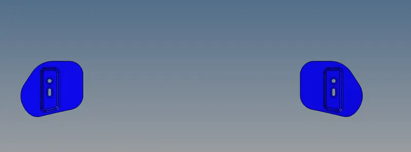
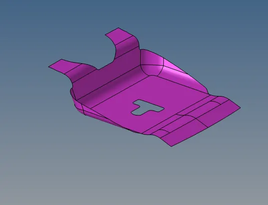
Hinges Mid surface Latch Midsurface
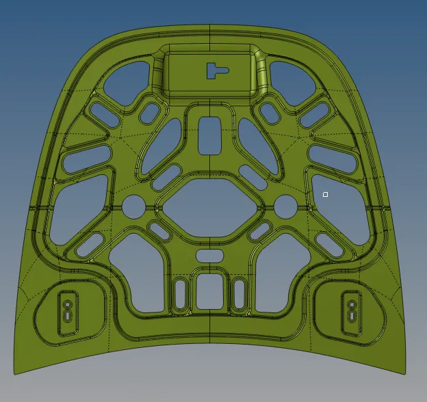
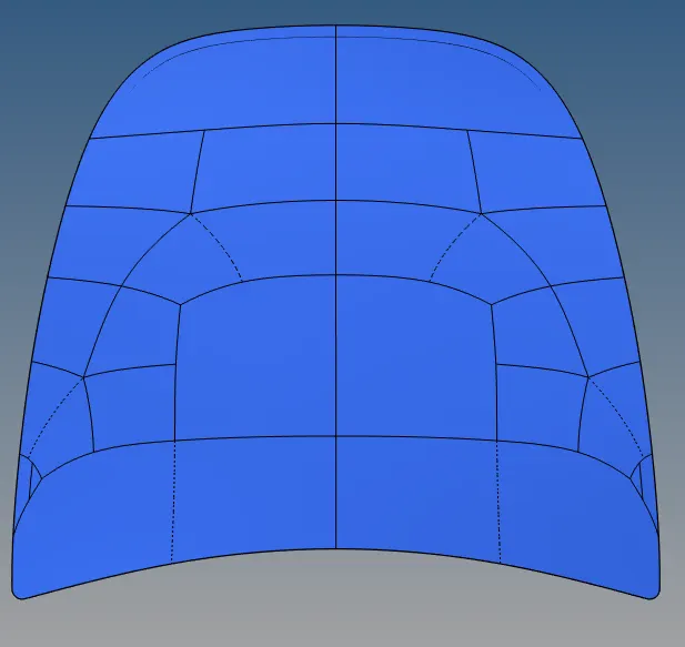
Inner Panel Midsurface Outer Panel Midsurface
Geometry clean-up: The unnecessary lines were suppressed using Geom>quick edit>toggle. Redundant points were replaced using Geom>quick edit>replace points. Washer surfaces of 5mm offset were created around cut-outs using Geom>quick edit>washer split.
Meshing and mesh clean up: The parts were meshed with a target element size of 5mm. The resulting mesh was then checked for the quality criteria shown in Fig1 using Tools>check elems. The required criteria was fed in and the mesh was checked and modified by one or more of the following methods:
- Changing the number of elements along the edges.
- 2D>quality index>cleanup tools>element optimize.
- 2D>quality index>cleanup tools>place node.
- 2D>quality index>cleanup tools>split quads.
- 2D>quality index>cleanup tools>combine trias.
- Selecting certain elements and remeshing.
- Certain elements were split using 2D>edit elements>split and then meshed again.
Each part was meshed and modified separately. For the inner and outer panels, the geometric symmetry was exploited and only have the panel was meshed initially. The meshed half was duplicated and reflected along the symmetry line (refer figure below) using Tools>reflect>elems.
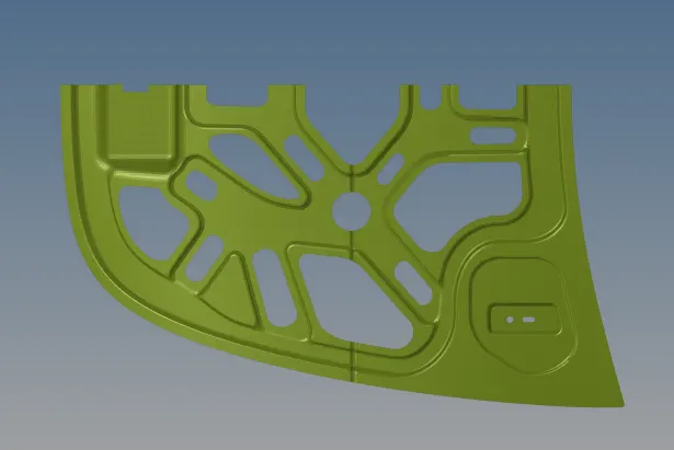
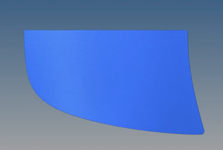
Inner panel half side mesh Outer Panel half mesh
Thickness: A PSHELL property card was created with a thickness of 0.75mm and assigned to all the meshed parts to get a 2D detailed element representation.
Results: The resultant mesh (including all the parts) included 93199 nodes and 91973 elements of mixed type with first order interpolation functions. The resultant meshed parts are as shown below:
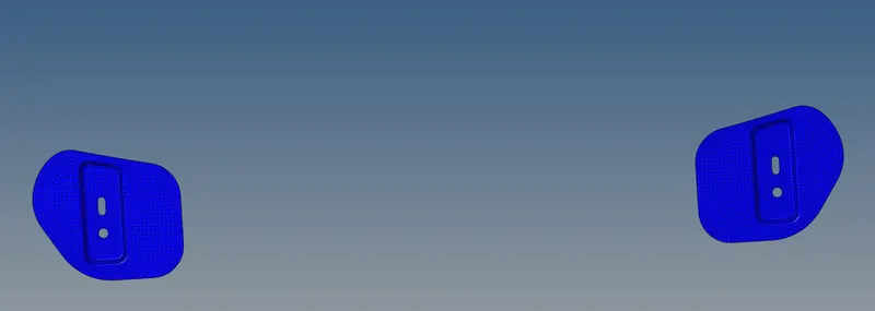
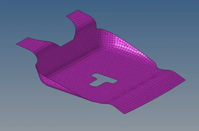
Hinges meshed Latch meshed
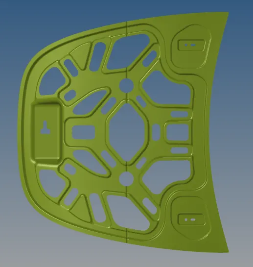
Inner panel meshed Outer panel meshed
The conformance to the demanded quality criteria was as tabulated below:
| Quality Criteria | Number of elements failing | Percentage of elements failing |
| Warpage | 164 | 0 |
|
Aspect Ratio |
632 | 1 |
| Skew | 212 | 0 |
| Min. Length | 1975 | 2.1 |
| Max. Length | 82 | 0 |
| Jacobian | 65 | 0 |
| Taper | 40 | 0 |
| Min tria angle | 38 | 1 |
| Max tria angle | 29 | 1 |
| Min quad angle | 250 | 0 |
| Max quad angle | 276 | 0 |
There are a total of 2923 tria elements in the mesh which is 3.1% of the total 91973 elements in the mesh.
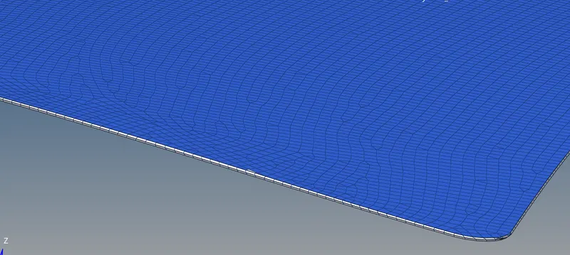
Most of the failing elements were on the curved filleted surface of the outer panel (white elements in the image below) where the geometry was very small and could not be simplified further.