Week 6-Meshing of Hood Challenge
Meshing of Hood challenge:
A car hood also referred to as a bonnet in some other countries is the hinged cover that rests over the engine of a front-engine vehicle. The hood is an integral part of a car that covers and protects the engine in a front-engine vehicle. While the outer panel acts as the car’s skin, the inner panel serves as a sound dampener that can eliminate or decrease typical engine noises.Car hoods are typically constructed from steel and sometimes from aluminum.we will be meshing the given car hood for crash analysis with mixed element.
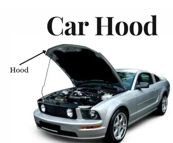
AIM: To extract the mid-surface from the given geometry(hood) and mesh the surface using the mixed elements with given quality criteria and element length and assign thickness to it.
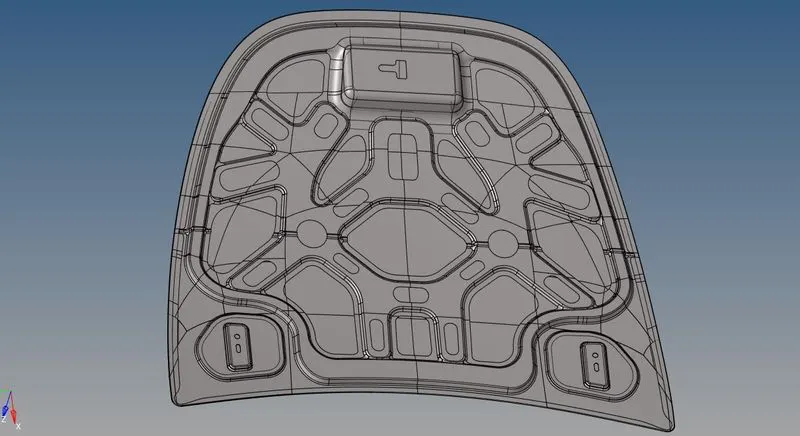
Fig.1: complete hood model
PROCEDURE: The hood model is imported to the hypermesh using open model in file option. There are 4 parts to the hood model. Inner extract, outer extract, latch and hinge reinforcement.
Inner extract:
We begin working on Inner extract. We delete the solid surface first using delete, solids from the tool bar. Then we proceed to create midsurface using mid surface in the geometry, in the main menu page. Then we upload the quality criteria and using auto clean up in the geometry, we clean the inner extract by toggling the feature line failing for minimum length criteria.
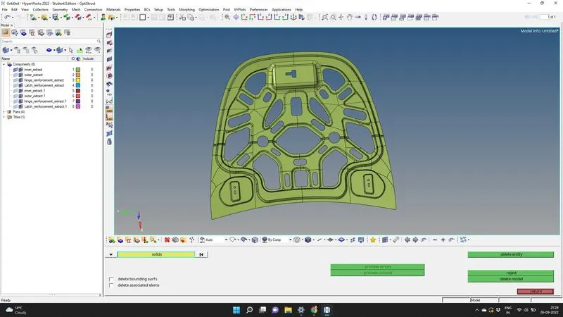
Fig. 2: Deleting the solid of inner extract
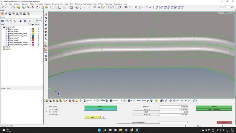
Fig. 3: measuring thickness of inner extract
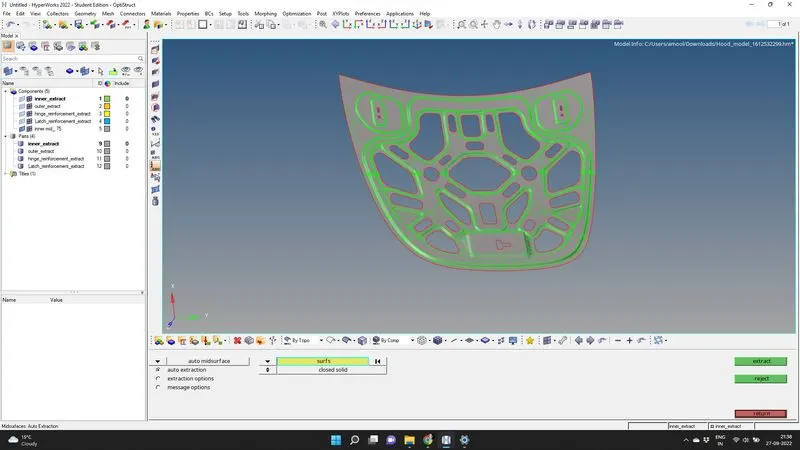
Fig. 4: automid of inner extract
as most of the part of the inner extract is symmetric axially , we can mask half of the surface before meshing. We can save this half view by pressing "v" in the keyboard and saving the view.
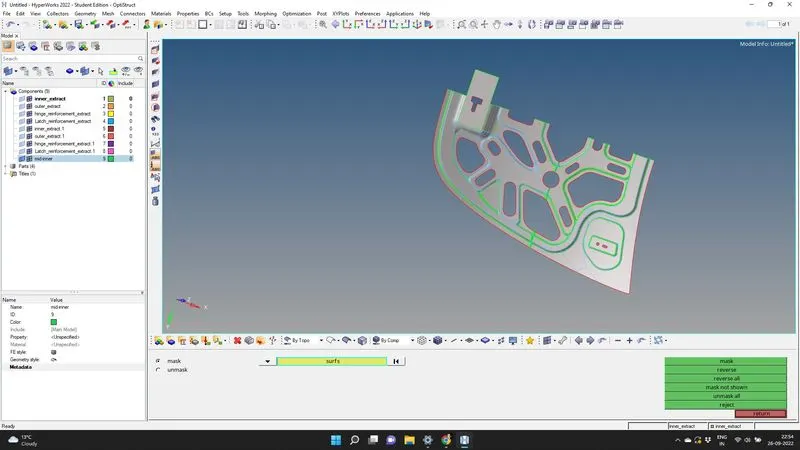
Fig.5: Masking the symetrical part of inner extract mid
The next step is to toggle unwanted lines and splitting lines for better meshing. After toggling we proceed to meshing each part of surface. We select the surface using automesh, in the 2D in the main page menu. There is no need for providing the washer split here.
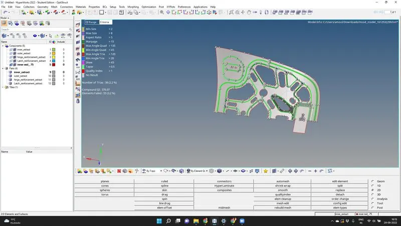
Fig. 6: automesh of the inner extract
we can rebuilt the mesh and keeping the view in elemental quality we proceed to improve the mesh flow. We use split and combine in edit element in 2D option in the main menu page, functional short keys like : F3 for replacing nodes, F7 for alligning the node, shift+ F12 for smooth. Alternatively we can use clean up tools in quality index to improve the mesh quality.
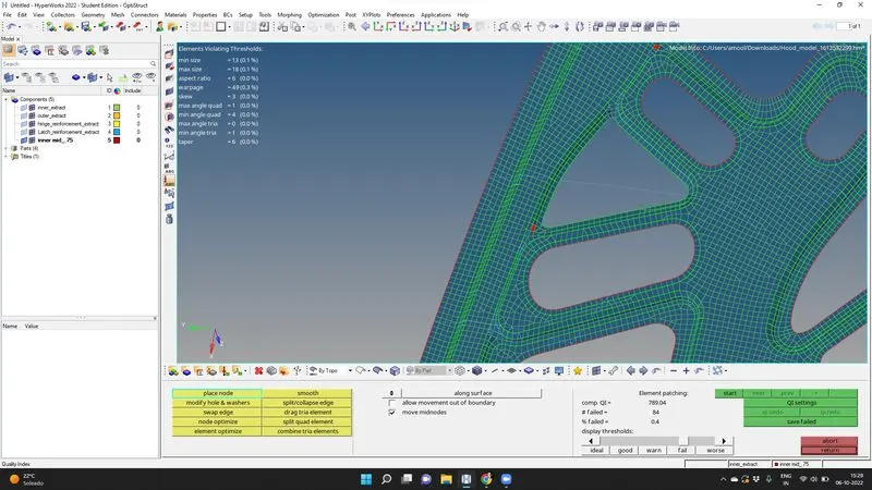
Fig. 7: Quality index for better mesh flow.
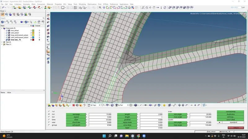
Fig. 8: Element clean up of the inner extract
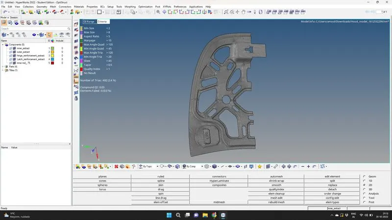
Fig.9: Half meshed surface of inner extract
After a satisfactory meshed part we proceed to refect the elements using elements reflect to plane, in tool option in the main menu page. we select vector directions N1,N2,N3,B (base point) and select all the elements to duplicate and reflect. We should keep the midsurface of inner extract as current component.
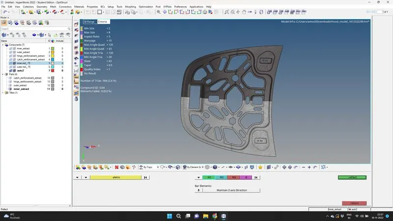
Fig. 10: Reflect option for axial symmetric elements in inner extract
We find the reflected elements are created as a seperate elements, which happens when the current component is changed. It can be retrified using organise , in the tools option in the main menu. Selecting those elements in the collector and changing the destination to inner extract mid, we can have the complete elements in the inner extract mid.
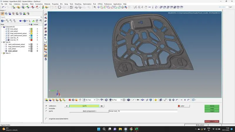
Fig. 11: organise option for having all elements in same meshed component.
To ensure proper connectivity between the reflected elements, we select edges from tool option in the main menu page. In the Edges, we select all the elements and find the free edges first and then we select preview equivalence to find all the region where the elements connectivity is disturbed and we use equivalence with a tolerance value of 0.1 for ensuring the required element connectivity.
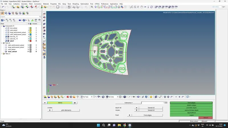
Fig. 12: Equivalence of inner extract component
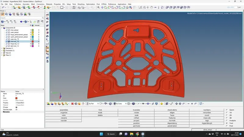
Fig.13: Meshed inner extract component.
Outer extract:
Now for outer extract , we begin by deleting the solids and measuring the thickness. We generate mid surface using midsurface option in geometry, in the main menu page. Then we do the auto clean up using geometry option in the main menu page.
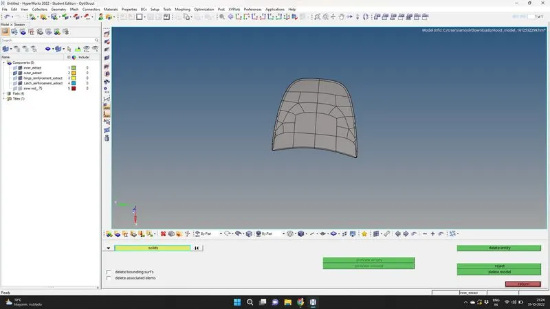
Fig. 14: Delete solids in the outer extract
As the componet is axially symmetric, we can mask the half of the midsurface and try to toggle those line, which fail for minimum quality criteria. We use split surface node option in the quick edit for creating lines which help in generating a good mesh flow.
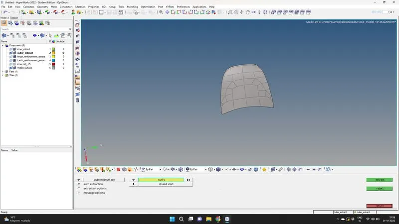
Fig. 15: Midsurface of the outer extract
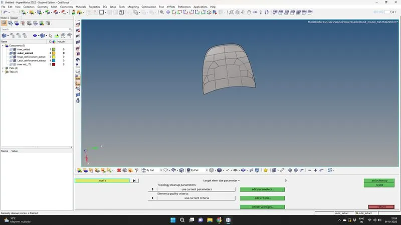
Fig. 16: auto clean option for toggling the unwanted lines
We mesh the surface by using automesh, in 2D in the main menu page. We rebuilt the mesh, check the quality index and use element clean up for a better mesh flow.
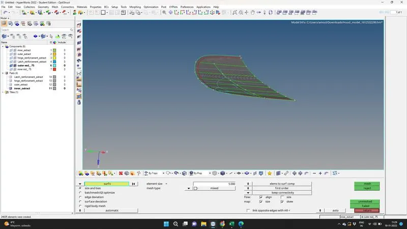
Fig. 17: automesh of the part of outer extract component
After having a satisfactory mesh flow, we proceed to reflect the mesh using Reflect option in tool, in the main menu page. For reflect by plane, we select all elements, by duplicate and choose the direction using vector N12,N2,N3 and base B.
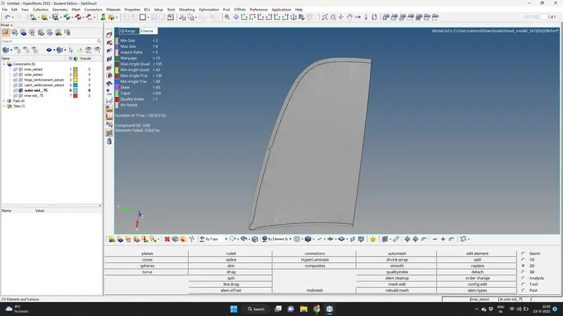
Fig. 18: Meshed outer extract component
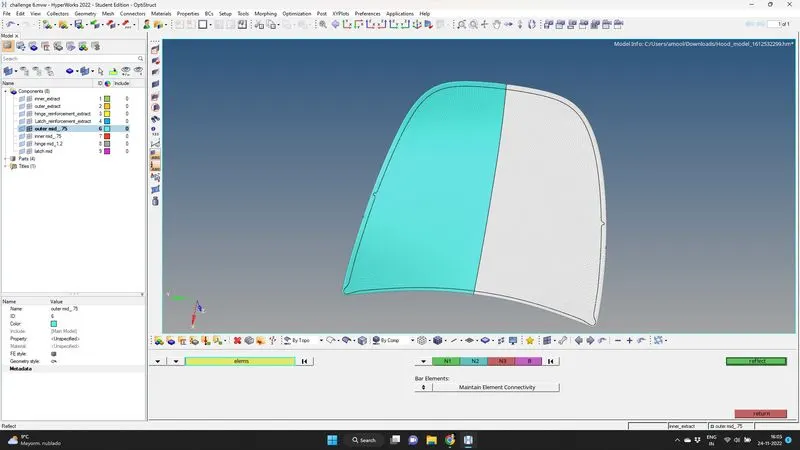
Fig.19: Reflected outer extract component
We find the reflected elements are created as a seperate elements, which happens when the current component is changed. It can be retrified using organise , in the tools option in the main menu. Selecting those elements in the collector and changing the destination to outer extract mid, we can have the complete elements in the outer extract mid.
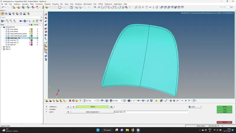
Fig. 20: Meshed elements in Outer extract component.
After reflecting, we proceed to ensure proper connectivity between the reflected elements using edges, in tool, in the main menu page. We select preview equivalence and set a tolerance of 0.l. Then we do equivalence to obtain a meshed outer extract component.
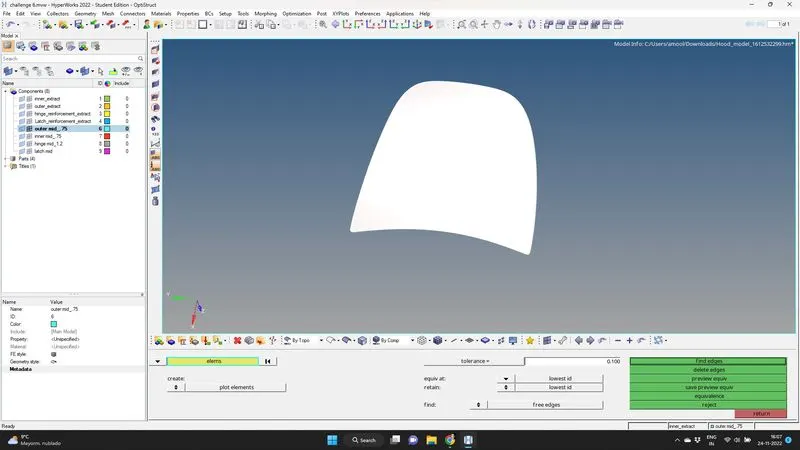
Fig.21: Equivalence for ensuring better connectivity of elements.
The outer extract part of the hood model is meshed.
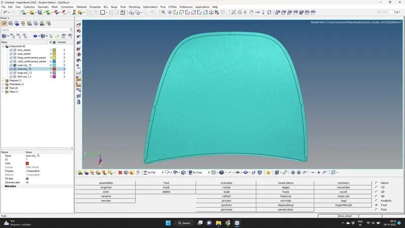
Fig. 22: Meshed outer extract of the hood model.
Latch reinforcement extract:
We begin by deleting the solid of the latch component. Then we generate the midsurface using midsurface, in the geometry option, in the main menu page. After the midsurface in generated, we do autoclean up of the geometry . We add a washer split of 5 mm around the hole, using quick edit in geometry option in the main menu page , Then we toggle the unwanted lines which fail for quality criteria, we proceed to generate mesh using automesh in 2 D option in the main menu page.
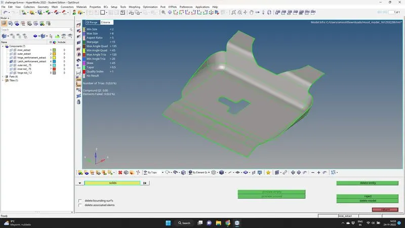
Fig. 23: Deleting solids of latch
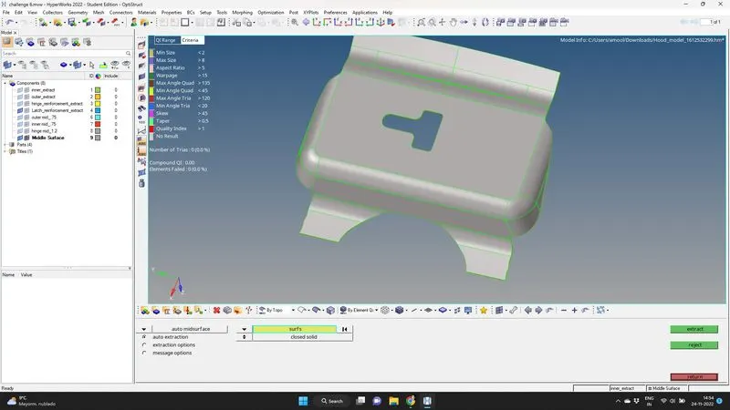
Fig.24: Generating midsurface of latch
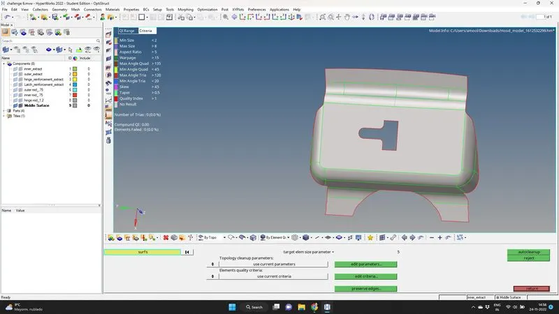
Fig. 25: Auto clean up of midsurface of latch
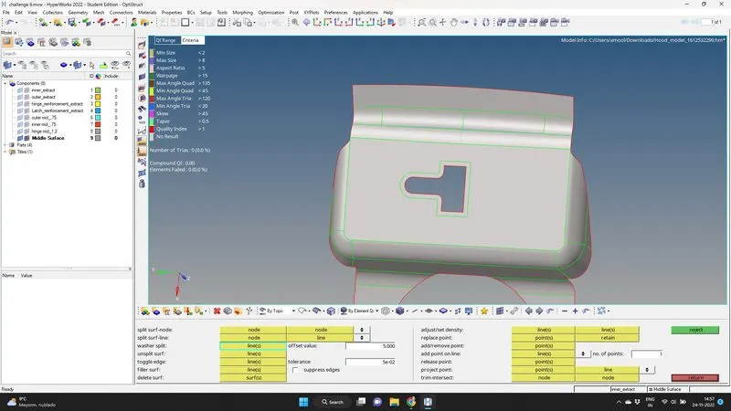
Fig.26: Adding washer split and toggling lines of latch
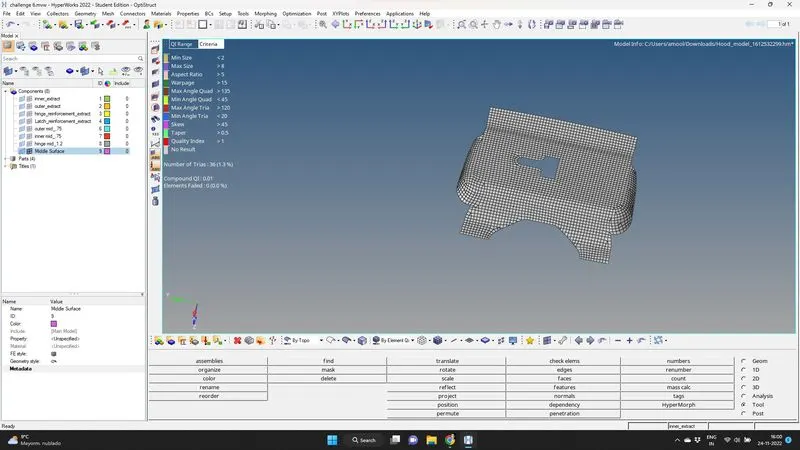
Fig.27: mesh improvement of latch surface
After having a satisfactory mesh flow using rebuilt, quality criteria and element clean up option. we obtain a meshed latch reinforcement extract.
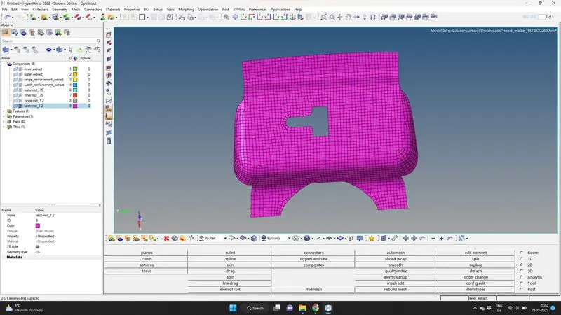
Fig. 28: meshed latch
Hinge reinforcement extract:
We begin by deleting solid of hinge reinforcement extract. There are 2 parts and though it is similar we proceed to generate midsurface for both the parts using midsurface , in the geometry option in the main menu page. After the midsurface is generated we do auto clean up of the geometry.
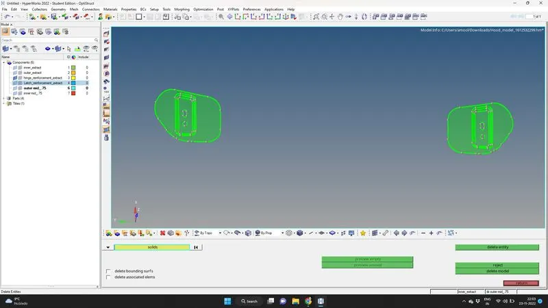
Fig.29: deleting solid of hinge
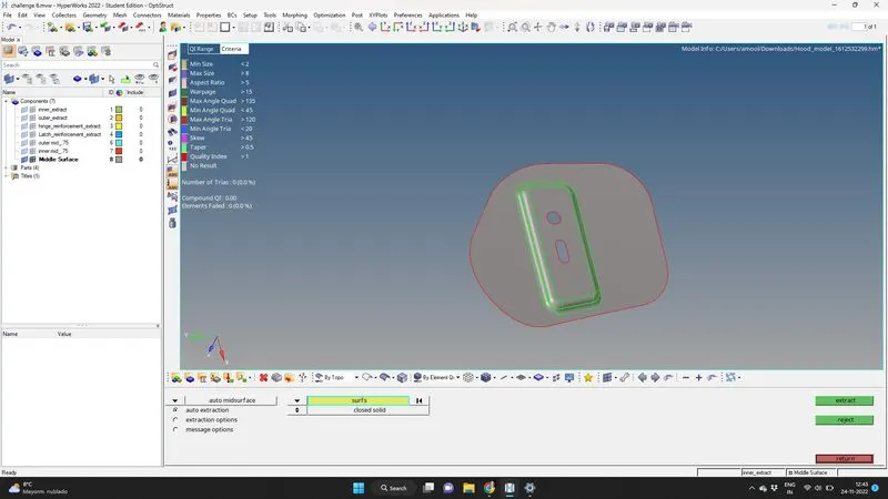
Fig.30: midsurface generated for the hinge
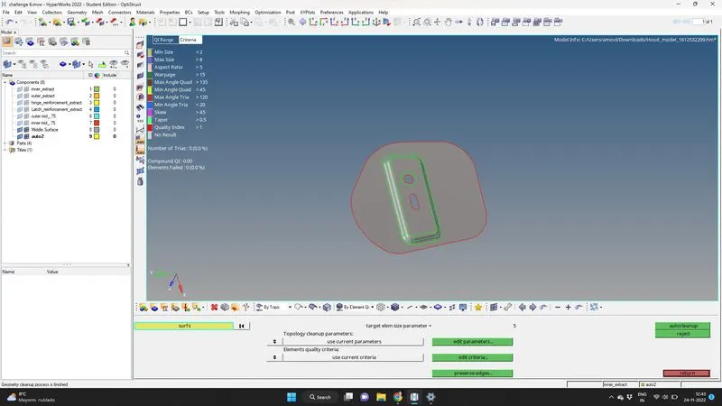
Fig.31: autoclean up of the hinge for toggling the lines failing for given quality criteria.
We toggle unwanted lines which fails in the given quality criteria and we proceed to generate mesh using automesh, in the 2 D option in the main menu page. The mesh flow is improved using rebuilt, quality index and element edit in the 2 D option, in the main menu page.
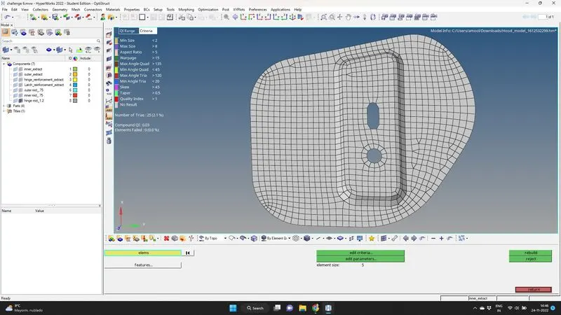
Fig.32: Mesh generated for the hinge.
The hinge reinforcement extract is meshed and a satisfactory mesh flow is obtained.
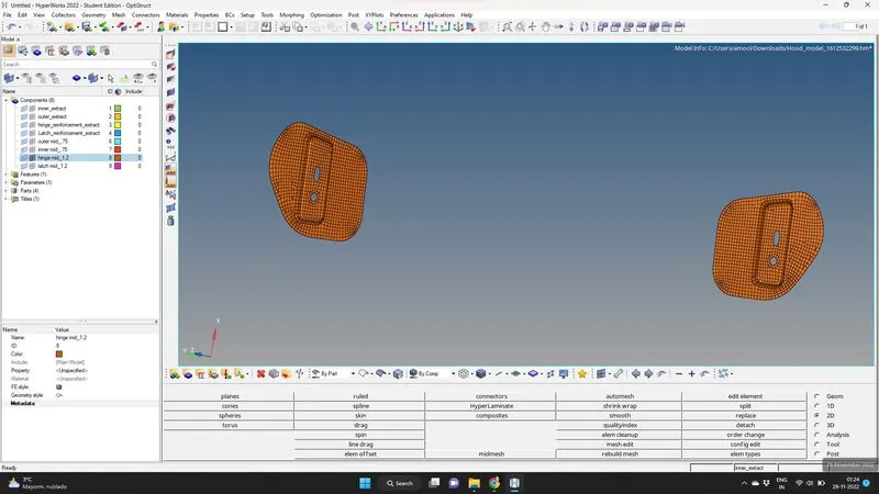
Fig. 33: Hinge reinforcement extract meshed
The meshed hood model as per the given quality criteria is obtained.
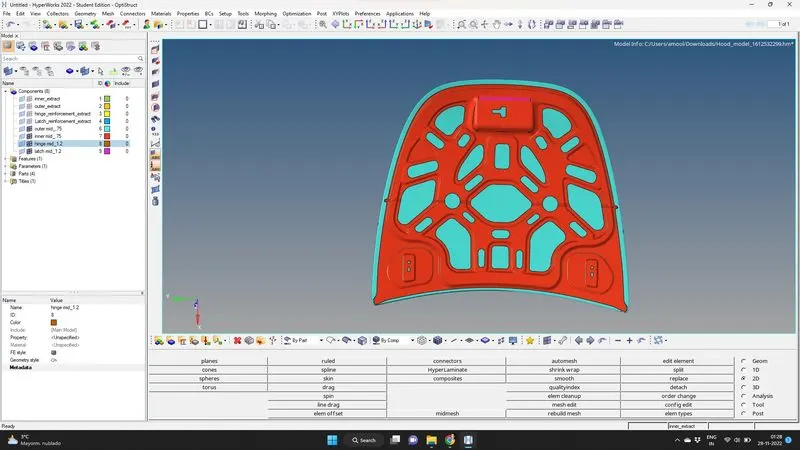
Fig.34: Meshed hood model as per given quality criteria is obtained.
After the meshing we proceed to assign thickness to each meshed components. We found that the inner and outer extract to be of the thickness of .75mm and latch, hinge to be of thickness of 1.2 mm. Two properties are created of thickness of 0.75mm and 1.2 mm each in Tab bar and each meshed part is assigned these properties as per the thickness measured. The view of the meshed componet with their thickness property is shown below ensuring the assigning of thickness to the hood model.
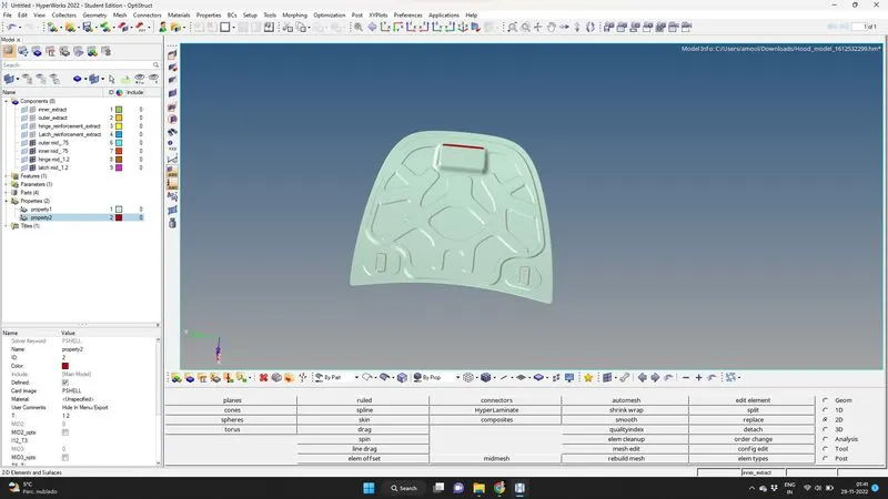
Fig.35: view of meshed hood model after assigning thickness .
LEARNING OUTCOME: Through this challenge, i was able to have a better understanding on meshing using hypermesh. I was able to rebuilt the mesh, improve the quality of the mesh and learned to use tools options like reflect, organise and equivalence using edge option.
CONCLUSION: Various parts of meshed hood model as per the given quality criteria is obtained.