Week 6-Meshing of Hood Challenge
AIM: - GENERATE THE MESH OF THE GIVEN HOOD GEOMETRY HAVING THE GIVEN QUALITY CRITERIA.
Objectives:
Generate mesh of the given hood geometry components separately, using the quality criteria.
Assign the thickness to the mesh.
To begin with the problem, the Hood model is imported into the Hypermesh environment and the profile used for this problem is Optistruct.
The Hood geometry consists of 5 different components, namely:
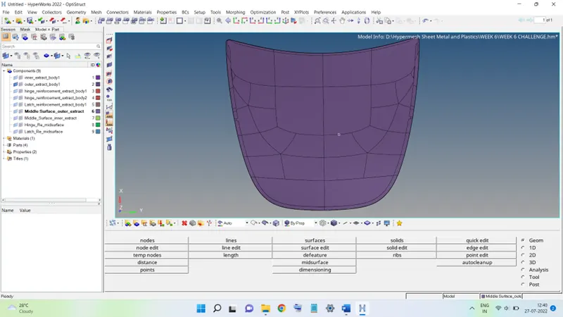
Outer Extract:
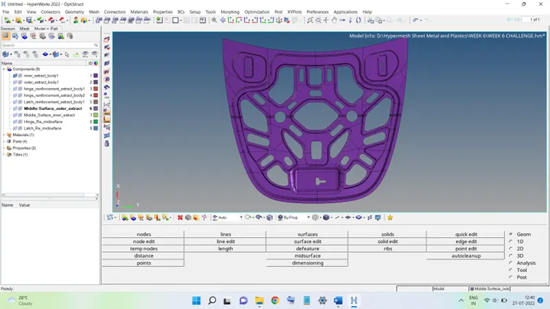
Inner Extract:
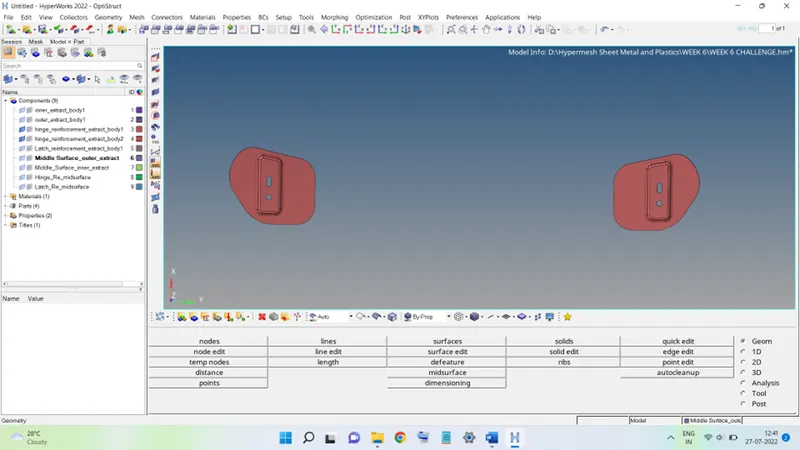
Hinge Reinforcement 1 and 2:
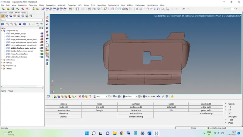
Latch Reinforcement:
The complete hood assembly looks like this:
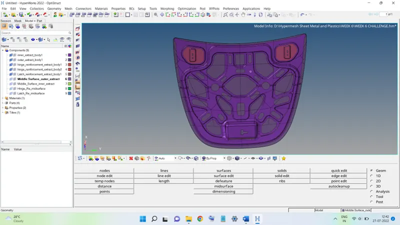
The procedure followed in generating the mesh of all components is the same and is mentioned below:
STEP 1: Delete the Solid bodies from the model if present.
STEP 2: Obtain the Mid-surface of each component and all the mid-surfaces must be present in different collectors.
STEP 3: Perform the geometry cleanup for each component in order to get a decent mesh afterward.
STEP 4: Mesh the component, the meshing may be done in a single stroke for simple geometry or it can be done piece by piece for the component having complex geometry and irregular surfaces (in the case of the Inner Extract Geometry).
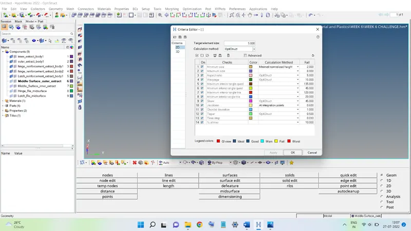
The Quality Criteria table to be used for meshing is given below:
|
S. No |
Quality Criteria |
Value |
|
1 |
Aspect Ratio |
5 |
|
2 |
Skewness |
45 |
|
3 |
Warping |
15 |
|
4 |
Taper |
0.5 |
|
5 |
Min. Length |
2 Units |
|
6 |
Max. Length |
8 Units |
|
7 |
Min angle Quad |
45 |
|
8 |
Max angle Quad |
135 |
|
9 |
Min angle Tria |
20 |
|
10 |
Max angle Tria |
120 |
STEP 5: Edit the mesh in order to eliminate the failing elements according to the given quality criteria data, provide a uniform flow to the mesh, and bring down the number of Tria elements present in the mesh.
STEP 6: Perform the various checks on the mesh to verify the mesh quality.
First Component: Outer Extract
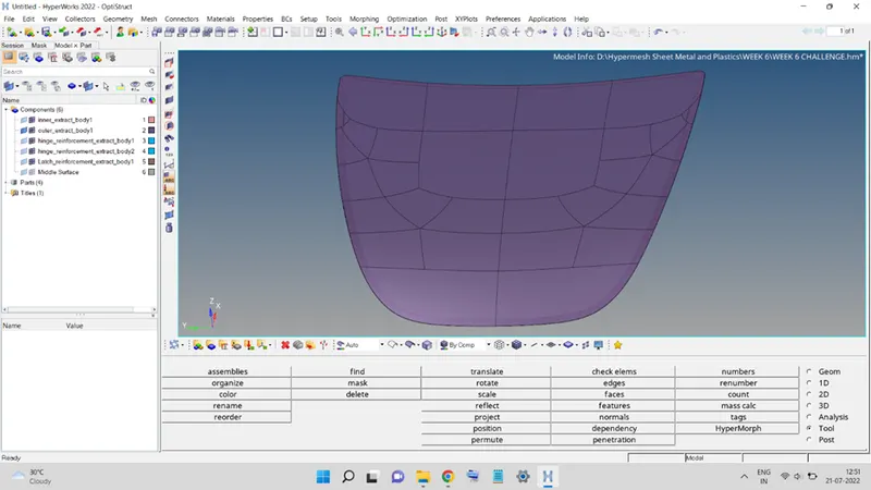
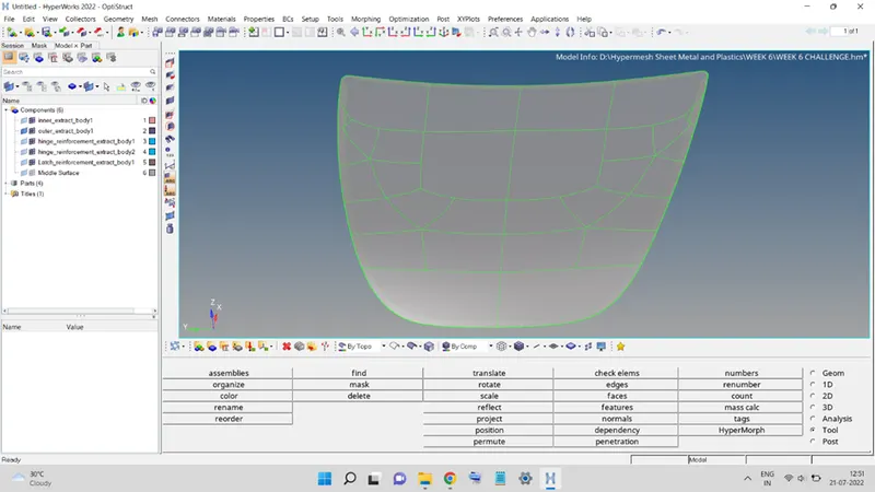
Generating the midsurface:
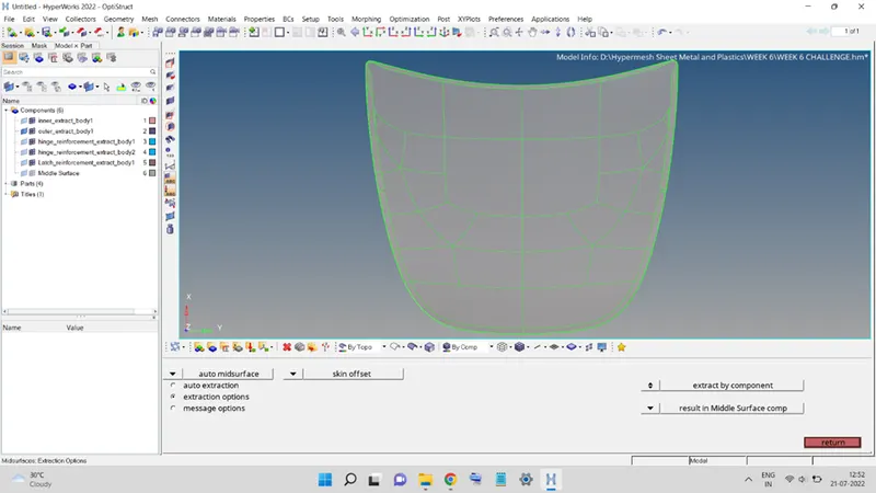
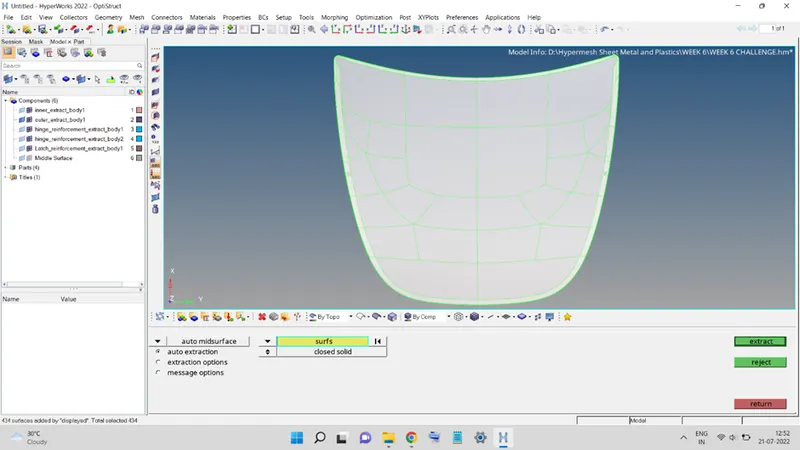
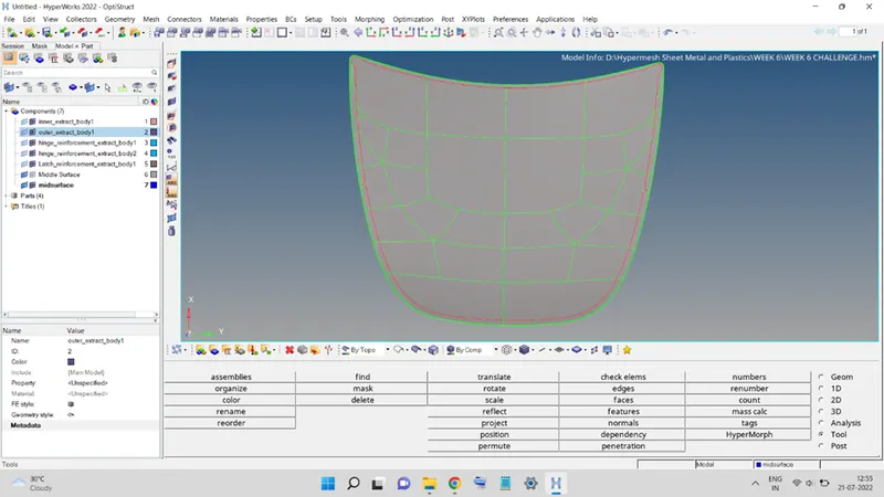
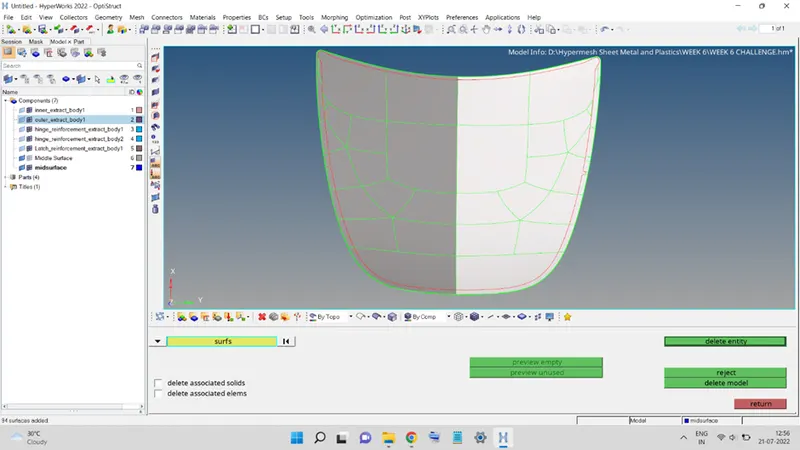
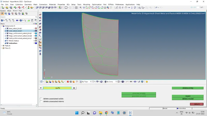
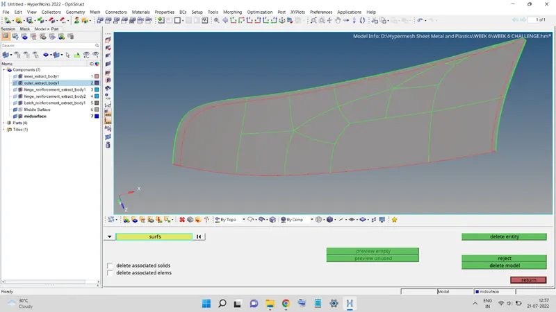
Since the surface is symmetrical about the X-Z Plane, the surface is split into symmetrical halves. The rest of the operations will be done on one of them and then later will be reflected in the symmetry plane to obtain the full surface.
Geometry Cleanup:
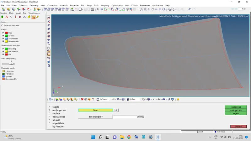
All the unnecessary edges were suppressed using the Edge Edit tool.
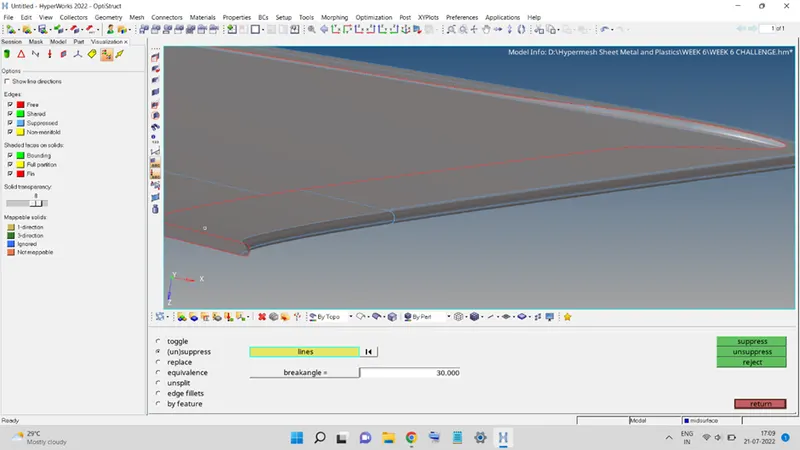
Since the Hemming region has surface dimensions lesser than the minimum element length therefore the Hemming region is split such that the minimum length error can be avoided.
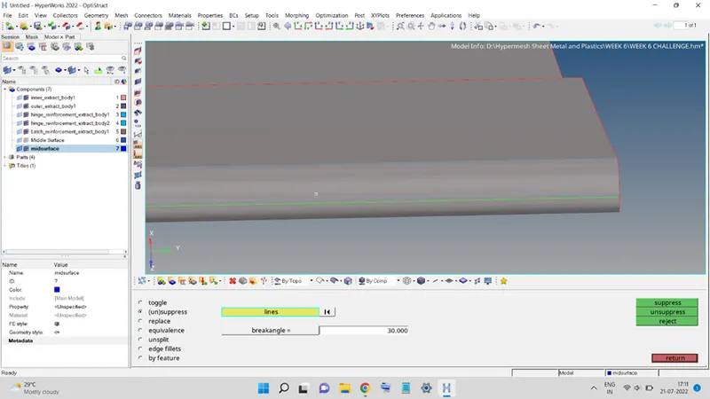
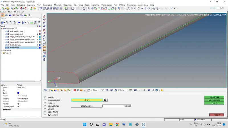
After successfully performing the cleanup, the surface looks like this:
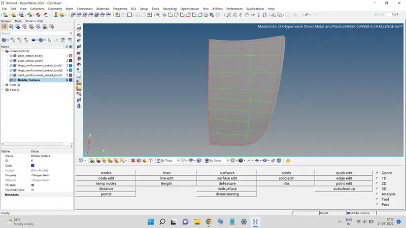
Meshing the surface:
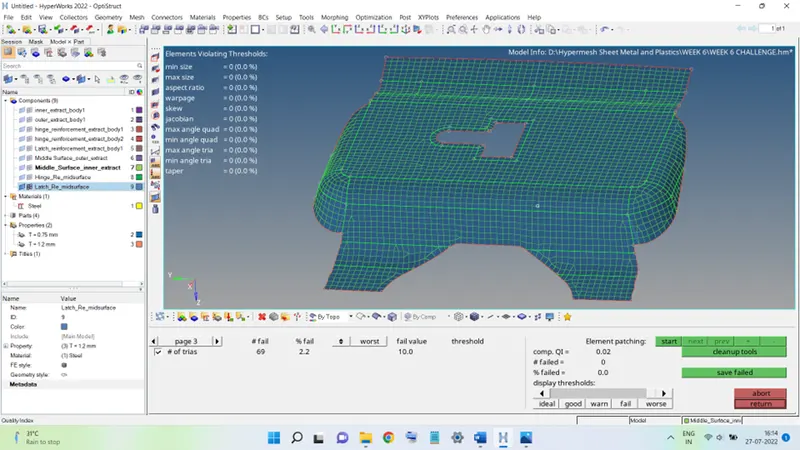
Values of the mesh Quality Criteria accepted for the given model are shown below:
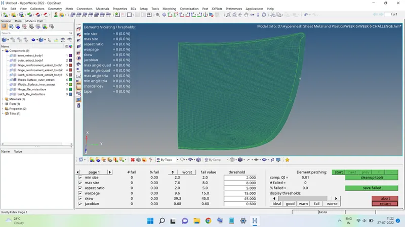
After successfully creating the mesh and performing the required operations to improve the mesh quality, the mesh with the violating elements is shown below:
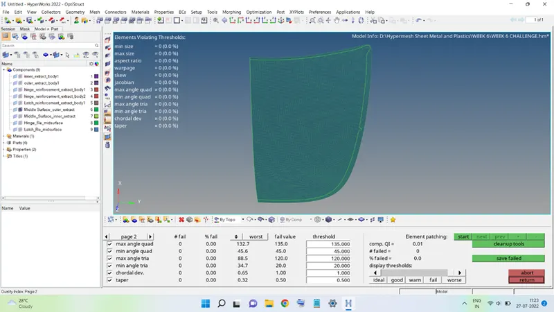
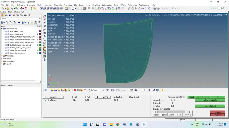
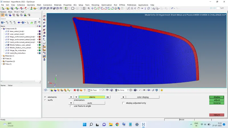
The alignment of the normals of the mesh elements is shown below, all the normals are aligned in the same direction.
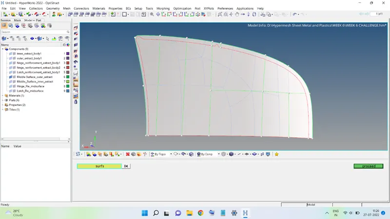
The comparison of the mesh and the surface was conducted and the Tolerance value of 0.2 was taken the comparison results are shown below:
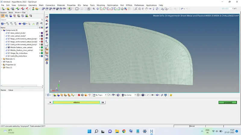
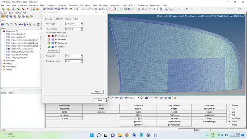
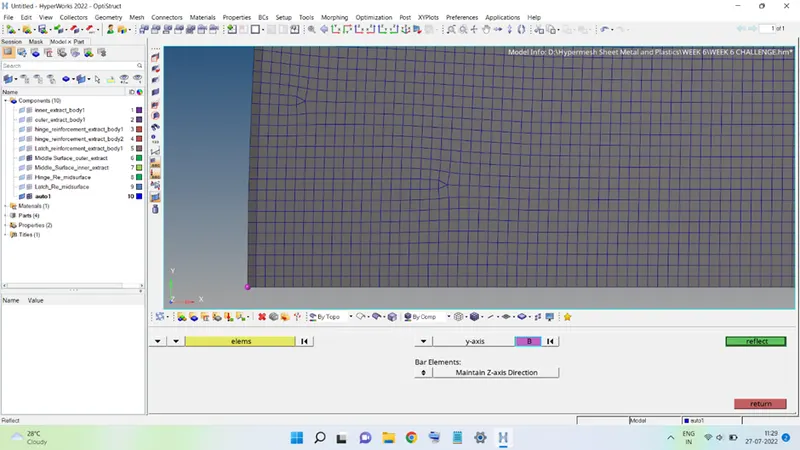
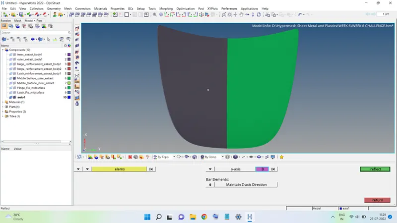
The mesh is then reflected about the X-Z plane and the base point is shown below and the mesh obtained after reflecting the duplicate elements is shown below:
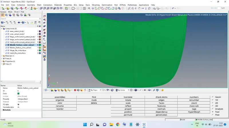
Checking the free edges present in the mesh:
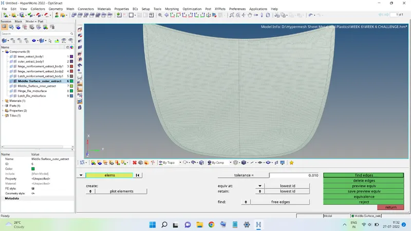
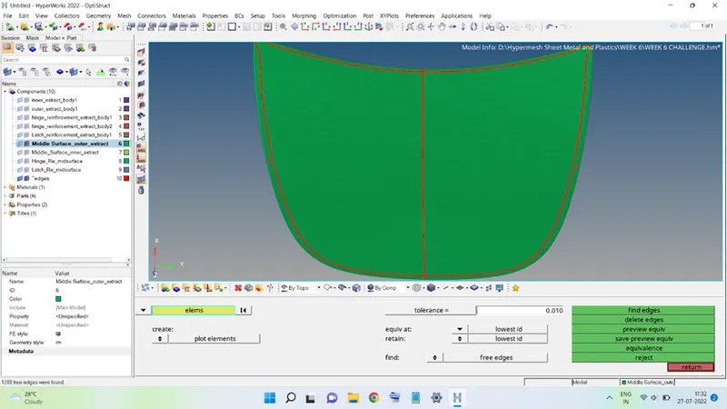
The free edge present in the middle is to be removed for the mesh to be continuous. The middle free edge is removed by first using the preview equivalence command and then followed by the equivalence command. The mesh after it will look like this:
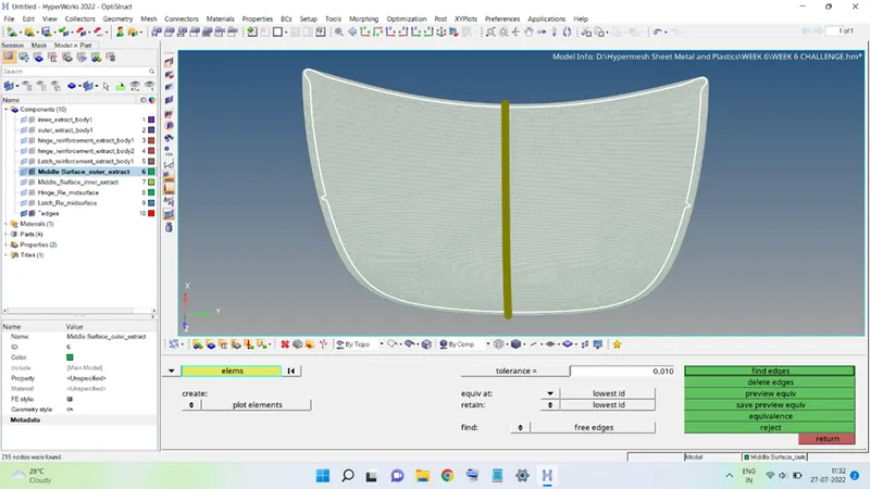
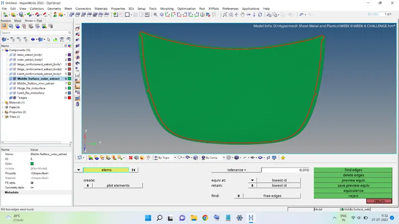
The mesh is successfully generated, the next step is to assign the thickness to this mesh. To do so a property was created, named T = 0.75 mm (having PSHELL card image), and assigned to the mesh as shown below:
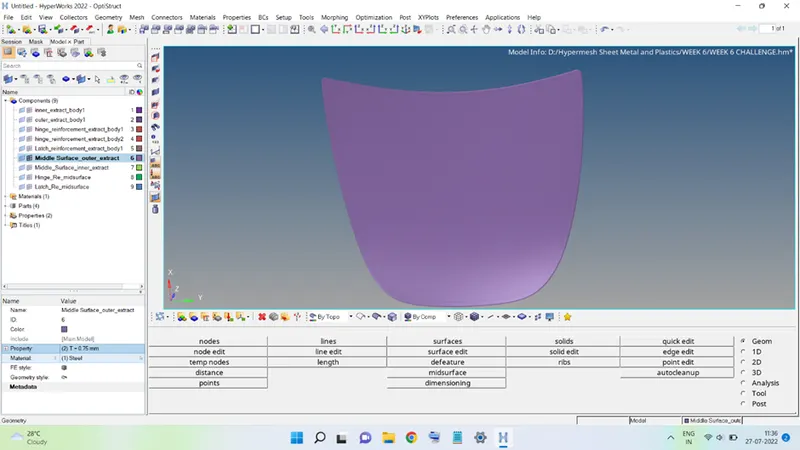
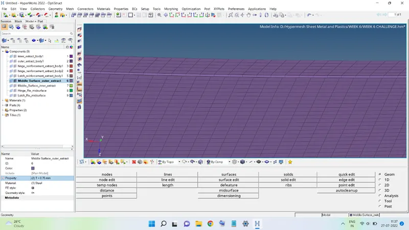
The above figure shows the mesh with the assigned thickness. The same process is followed for the rest of the components to generate the mesh.
Second Component: Inner Extract
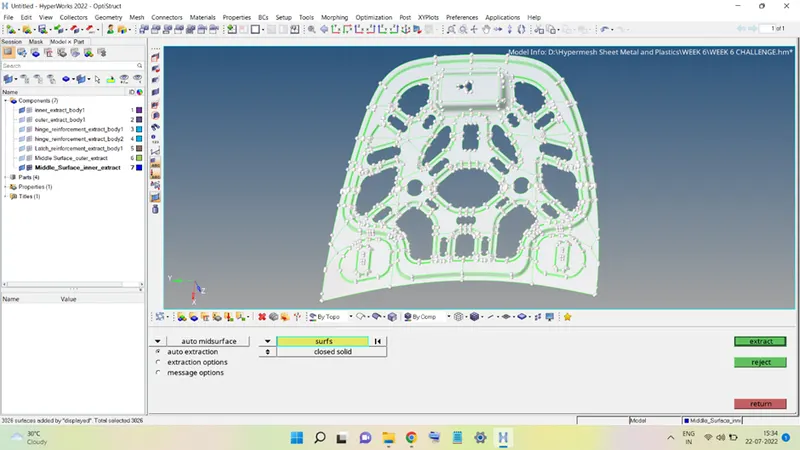
Mid-surface of this component was obtained and then moved to the component named Middle_Surface_inner_extract, as shown below:
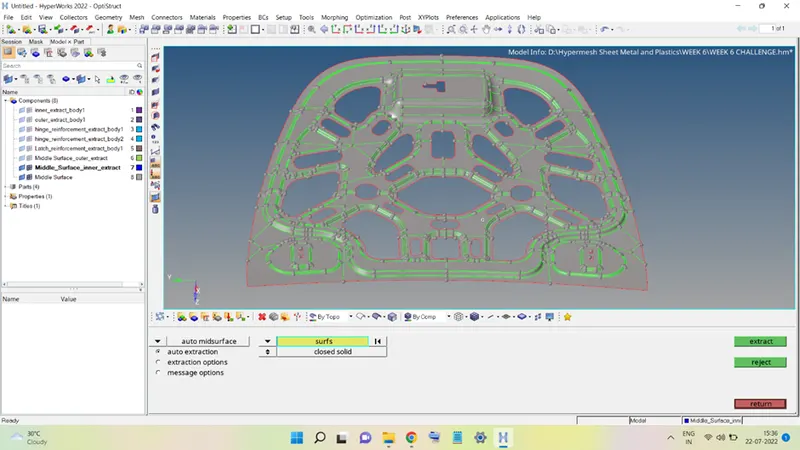
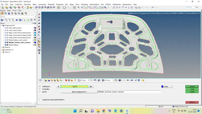
The mid-surface was then split into two symmetrical halves as shown below:
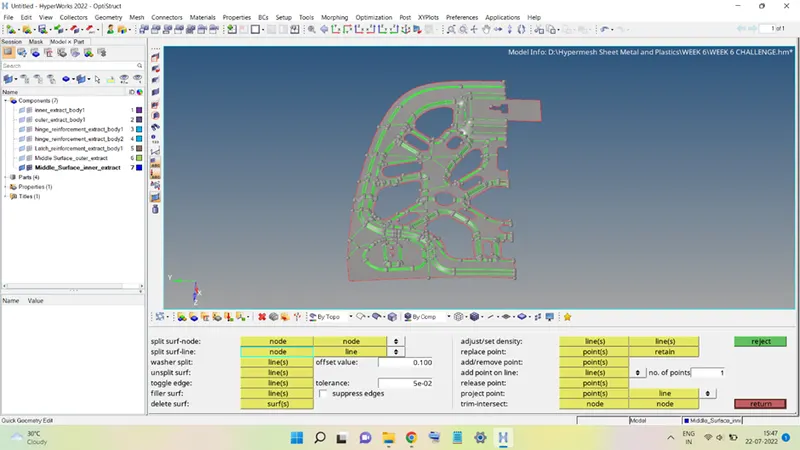
Next, all the unwanted edges present on the surface were suppressed and washer splits were added at the necessary locations to ease the meshing process.
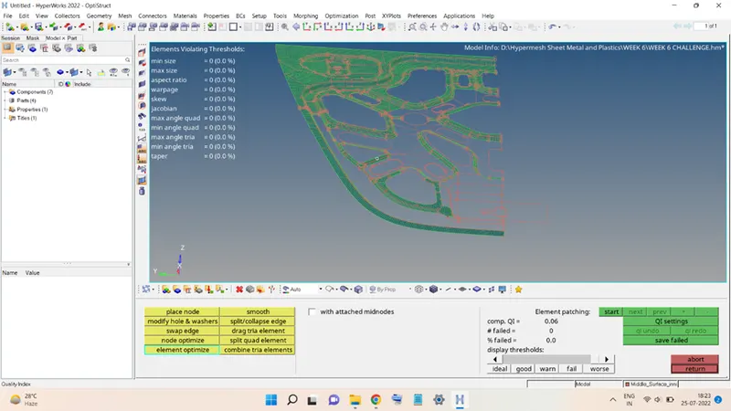
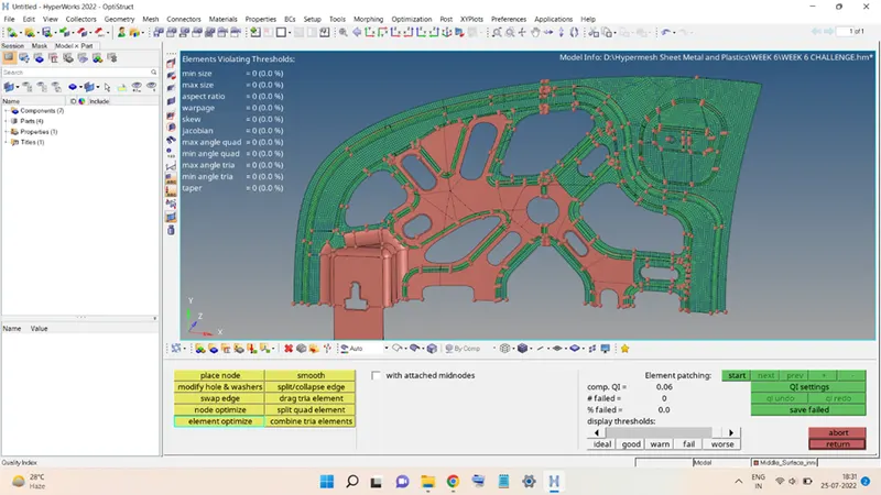
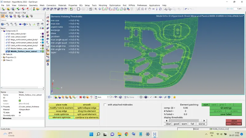
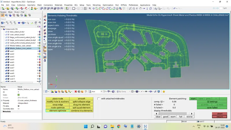
The component is meshed section-wise, first, the curved bends were meshed and optimized to be within the quality limits, and then the remaining areas. The meshing process is shown in the figures below:
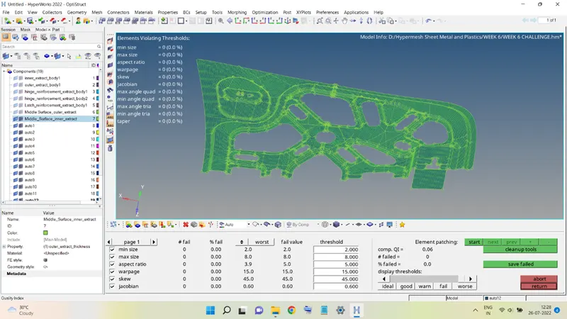
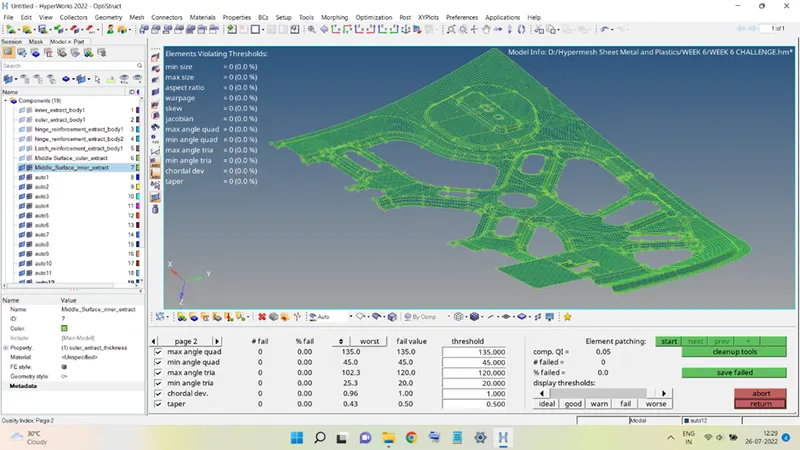
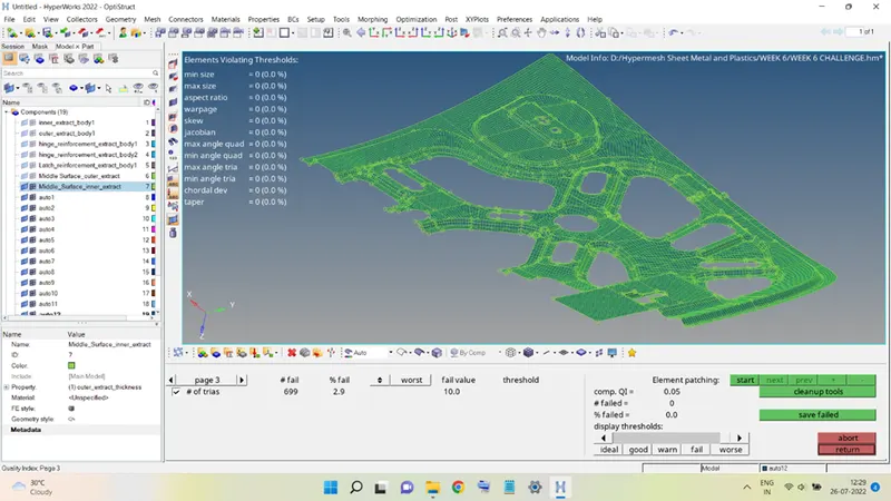
Finally, the mesh obtained will look like this:
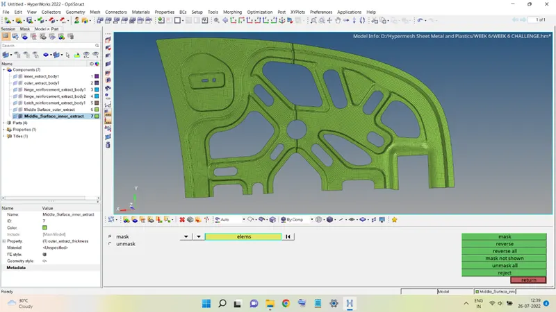
The mesh is then duplicated and the duplicate elements were reflected in the X-Z plane as shown below:
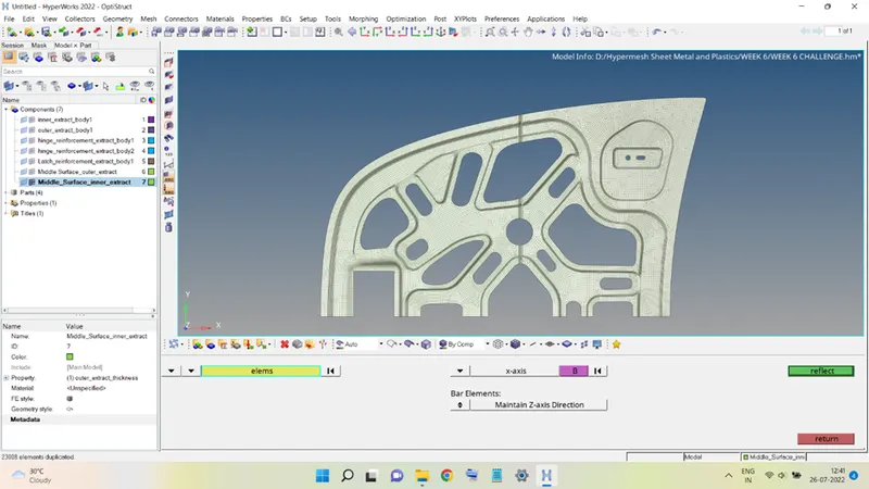
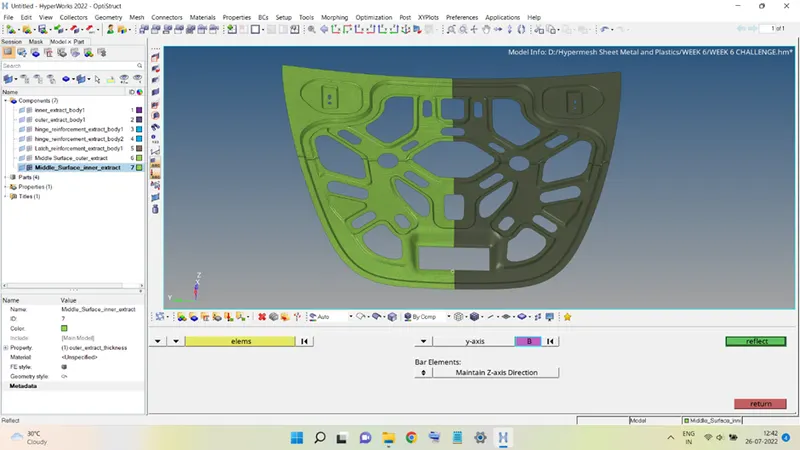
Next, the mesh was checked for the free edges and both the meshes were connected using the equivalence command, as shown in the figures below:
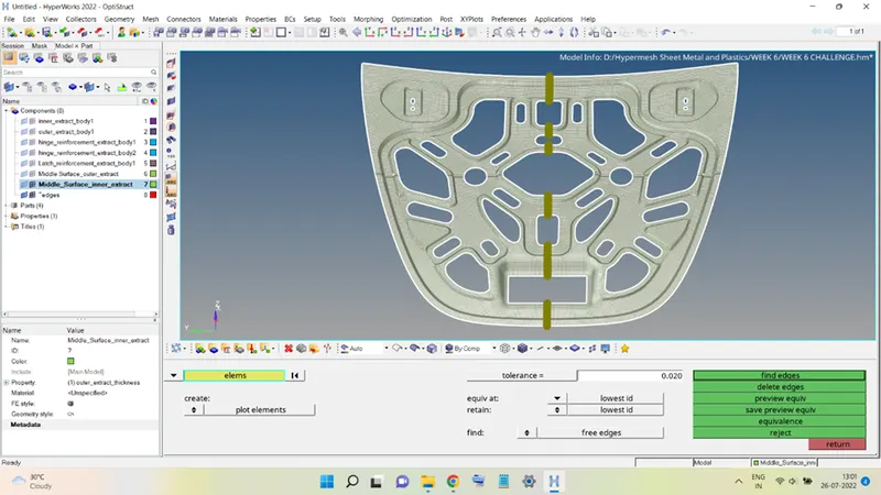
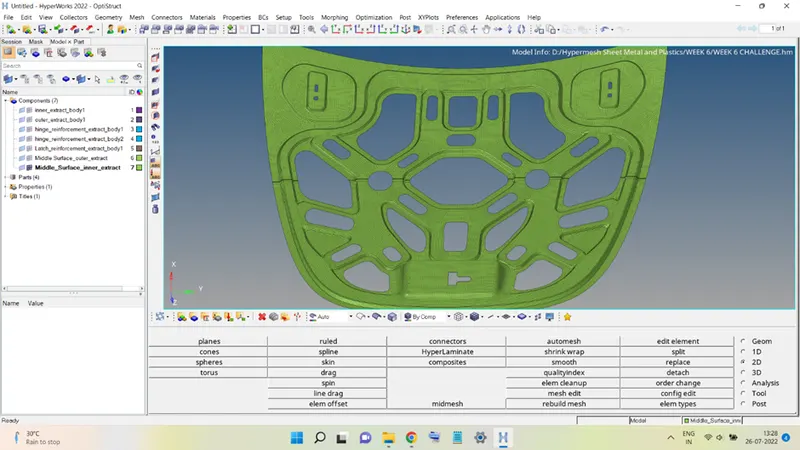
The mesh and surface were compared and the results are as follows:
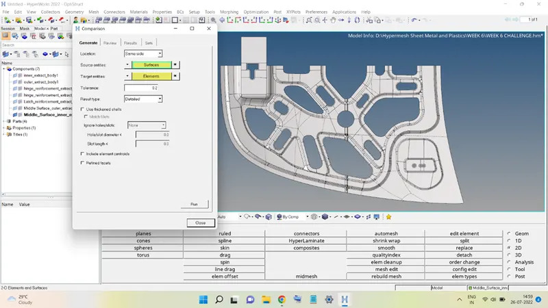
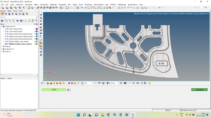
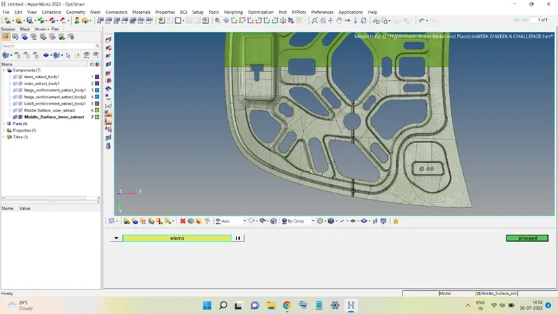
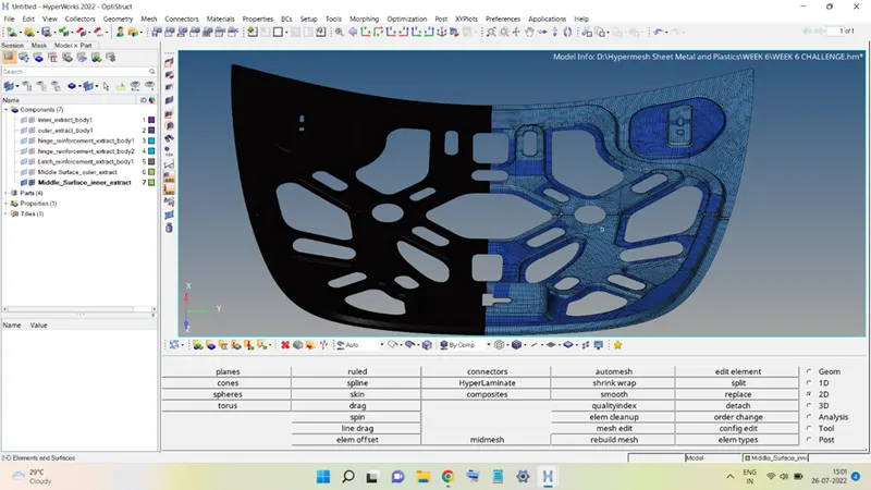
since the surface is only present for the left half, therefore the comparison result is available for the left half only.
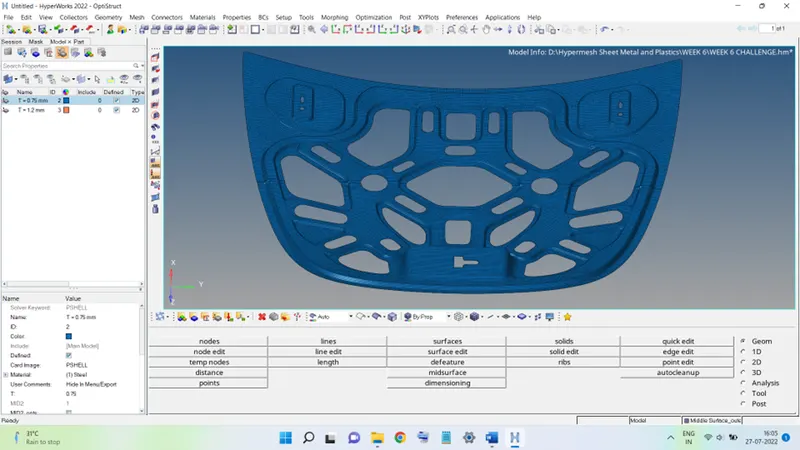
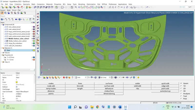
Lastly, the mesh is assigned with the thickness property named T = 0.75 mm, and the material is Steel, as shown below:
Third Component: Latch Reinforcement
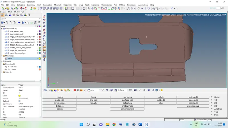
first, the mid-surface is generated and the obtained surface is then moved to the component named Latch_Re_midsurface. the mid-surface is cleaned up before the meshing is done.
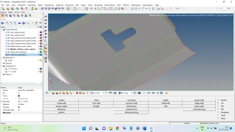
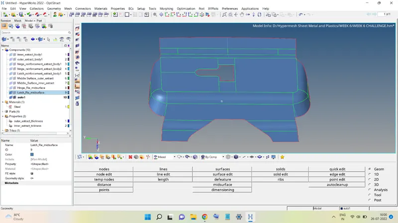
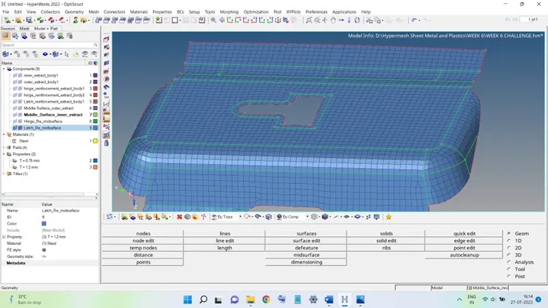
After successful geometry cleanup, the surface was meshed, and the meshed surface looks like this:
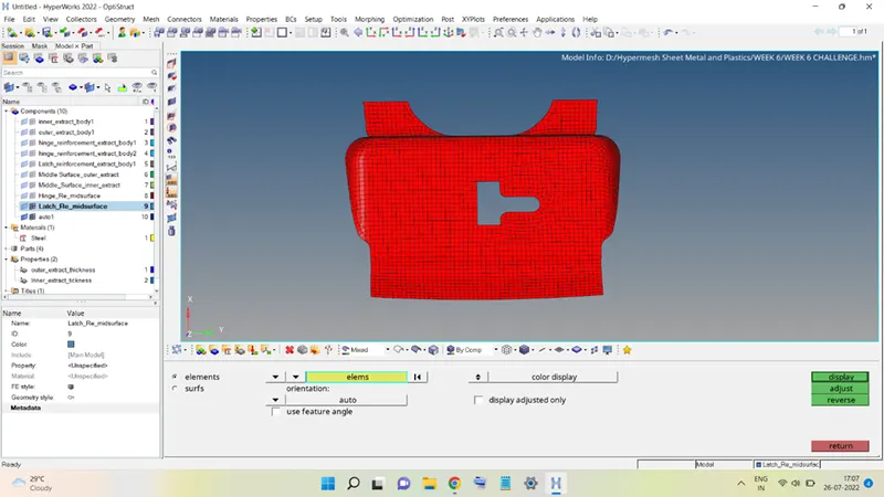
The alignment of the elements' normals is shown below:
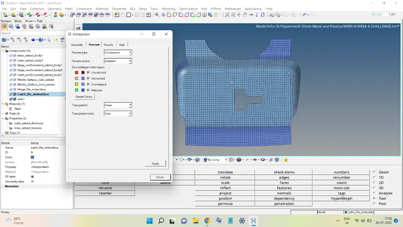
The comparison of the surface and the mesh was also performed as shown below:
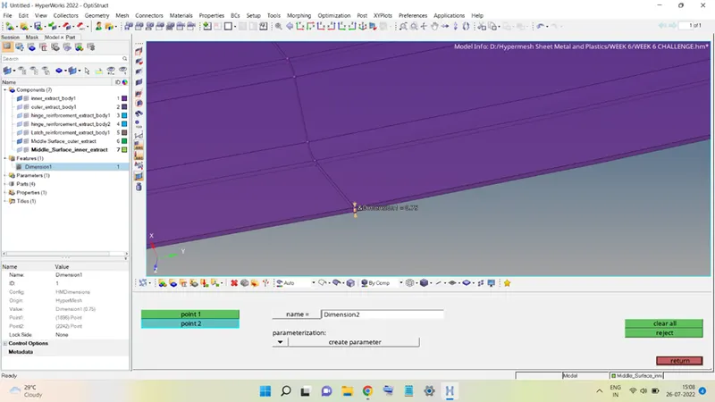
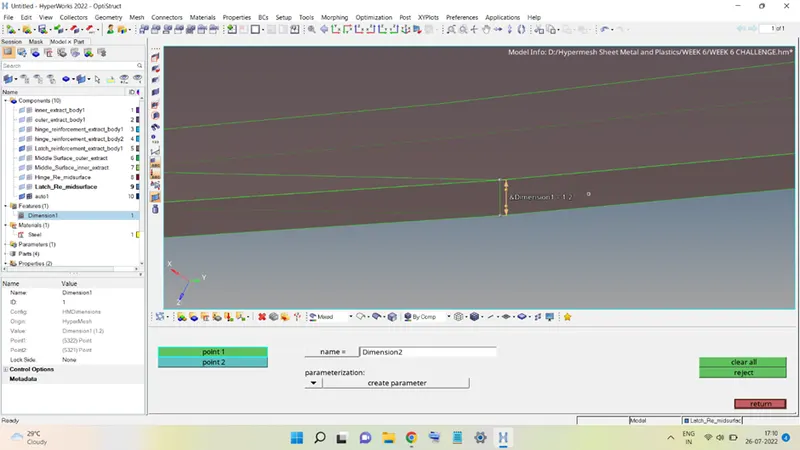
Next, the thickness must be added to the mesh, to do so, first the thickness of the parent surface was found using the Dimensioning tool. The thickness was found to be 1.2 units.
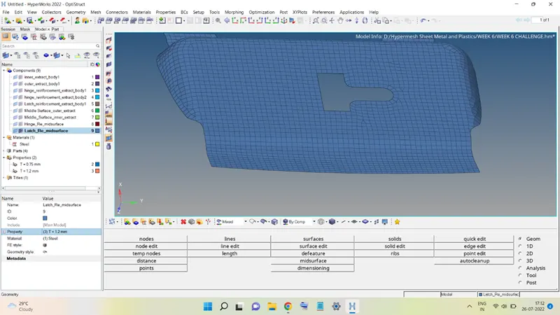
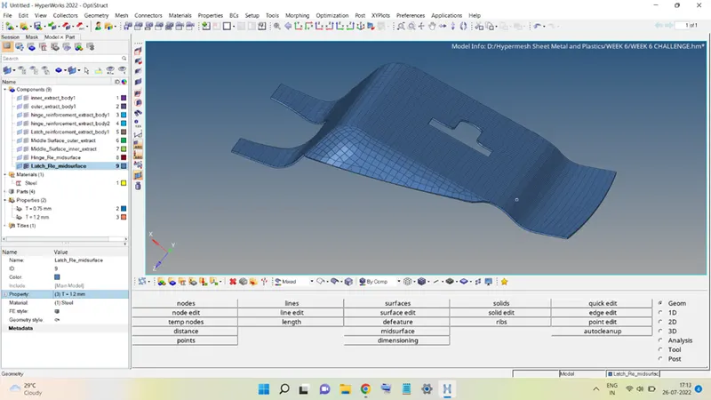
After that, a property named, T = 1.2 mm, was created having PSHELL card Image and the thickness as 1.2 units, and Steel as a material is also added to the mesh.
Fourth Component: Hinge Reinforcements
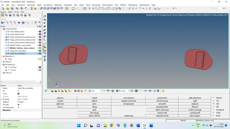
Mid-surfaces for both surfaces were obtained and saved in a single collector named, Hinge_Re_midsurface.
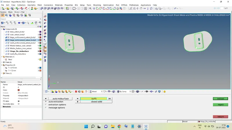
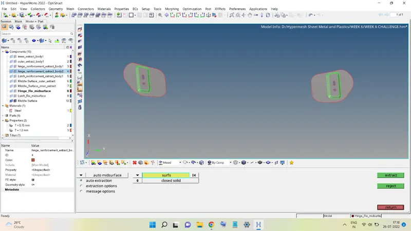
Each of the mid-surface is cleaned up to remove unwanted shared edges and adding the washer splits at the required locations, shown below:
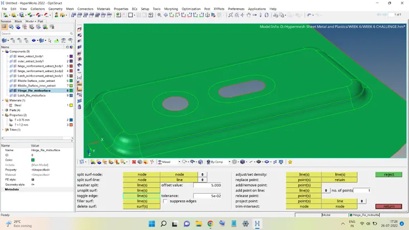
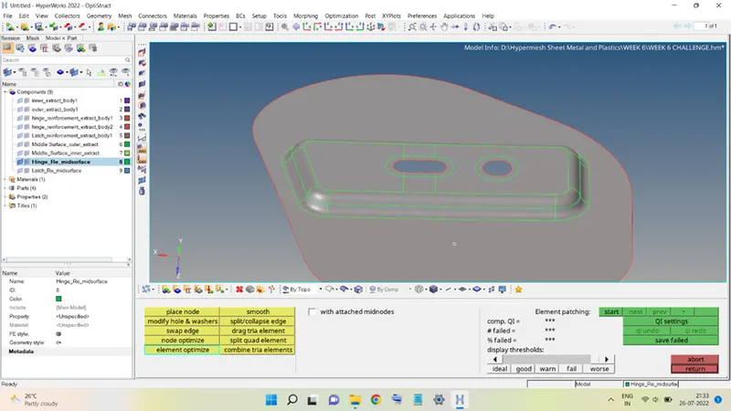
The surfaces were meshed and the mesh generated is shown below:
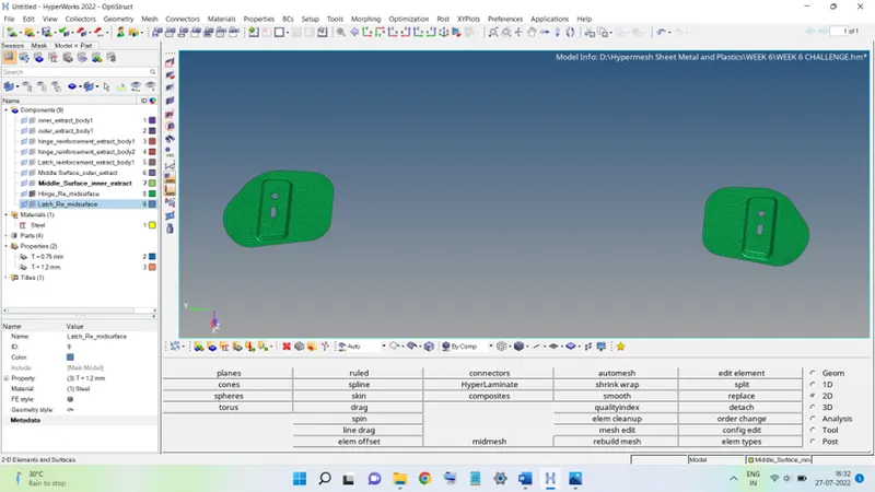
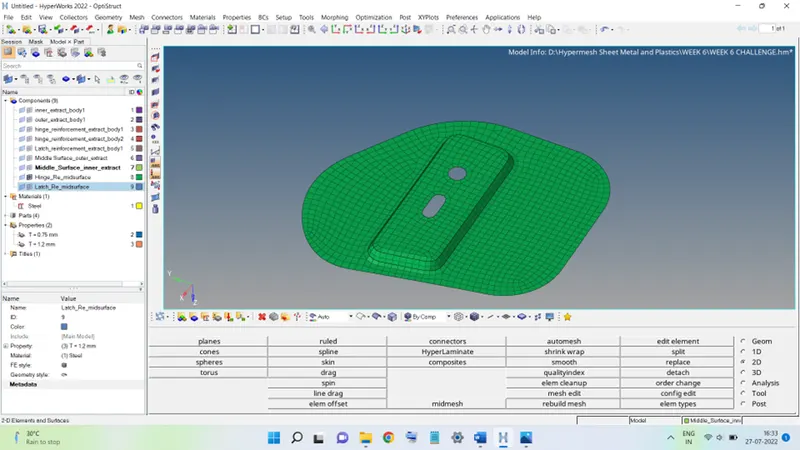
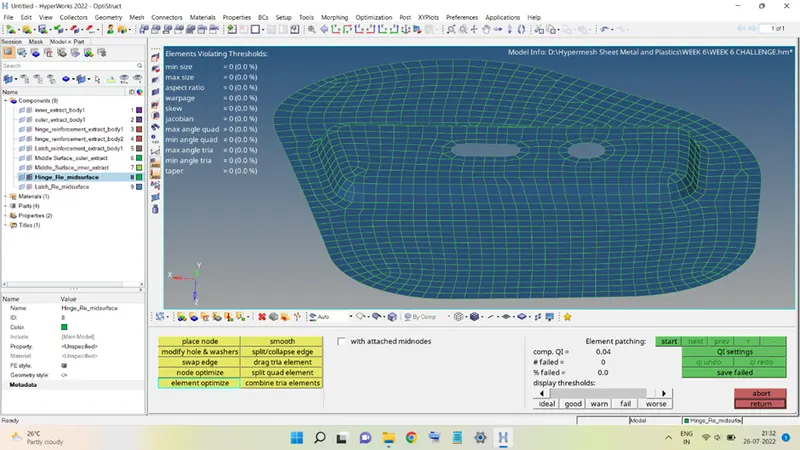
The mesh is checked for the alignment of the normals of the elements, as shown below:
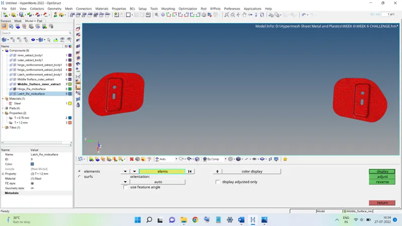
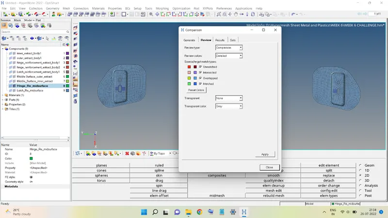
the mesh comparison results are shown below:
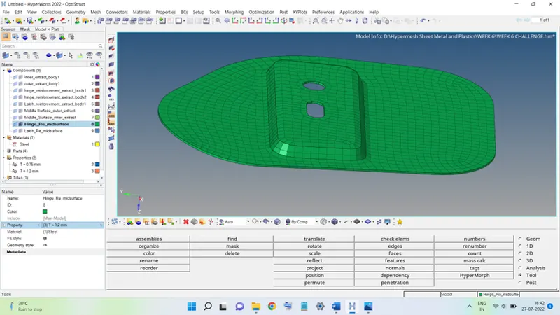
The mesh is then assigned the thickness using the Property named T = 1.2 mm and the material assigned is Steel, as shown below:
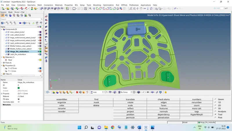
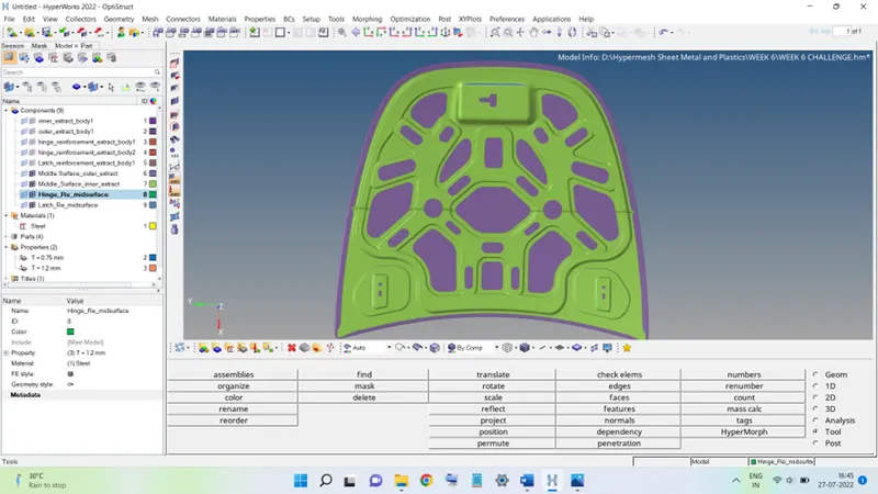
The complete mesh of the given Hood geometry consisting of all the generated mesh is shown below:
Conclusion:
Through this exercise, gained firsthand experience in meshing complex geometries.
Learned about the different operations that must be done to clean up the geometry before meshing it.
Learned to use different useful tools like Quick Edit panel, Toggle Edges, Surfaces Splits, etc.
Gained knowledge about the meshing quality criteria, parameters, and quality checks that a good mesh must always pass.
Learned how to use the meshing tolls like Auto-mesh, Quality Index, Edit element, Rebuild Mesh, etc.