Week 6-Meshing of Hood Challenge
Aim: Create the meshing of given Hood components of car by Hypermesh software under given Quality parameter.
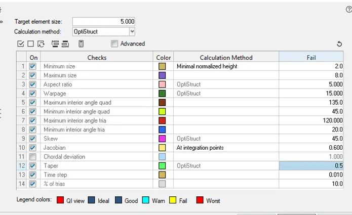
The given Quality parameter is:
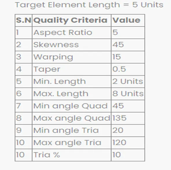
Theory: Hood of a car is a bonat or trunk of car which is used to protect the running performance parts of a vehicle. The opening and closing kinematic design of hood make easy of car maintenance
Its shape follow the criteria of Aerodynamic design which make the low resistance of air flow.
During collision of Accident, The design of hood play a important role. An active structure is capable of pushing the surface of hood away from the motor vehicles motor components in the event of crash. Spring force designs are often used in active hood design.
The Hood assembly consists of inner and outer panels, latch and hinge Reinforcement.
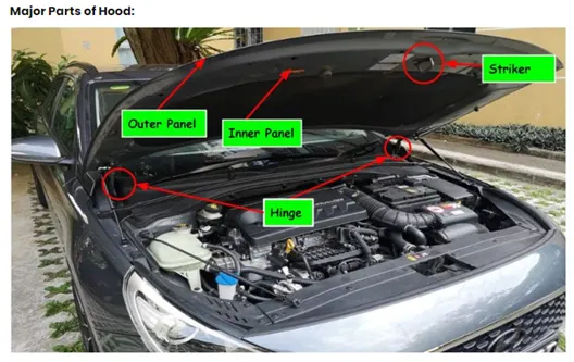
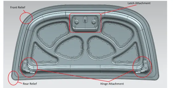
Procedure:
Latch
- Import the given model
2.Choose one model for operation. I selected Latch
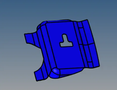
3.Input the Quality parameter
By (preferences < criteria file settings)
4.Create midsurface by (Geom< midsurfs< automidsurface< surface)
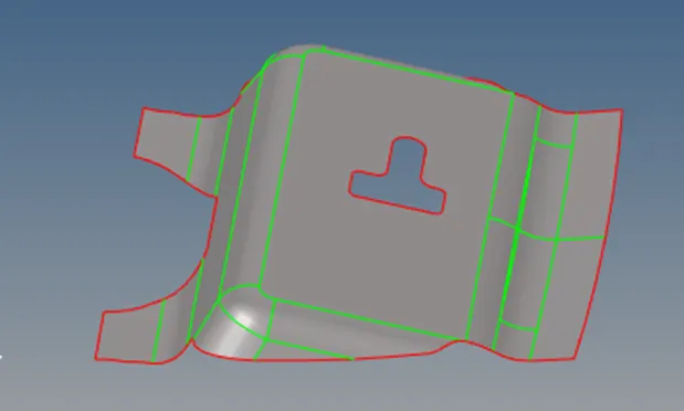
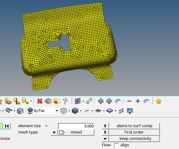
- Split the surface by lines (Geom < quick edit < split surface-line < node-line), By this process we can mesh part model one by one surface selection and create element and node as attached condition to each other. If we do not split surface and create automesh to model then a bad mesh will generate as given below.
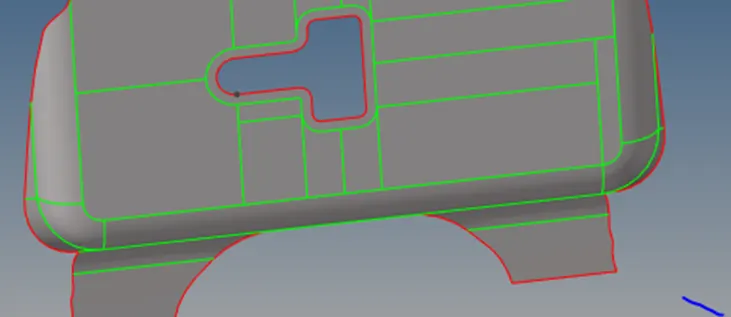
But if we split the surface as below
The generated mesh after splitting surface will be
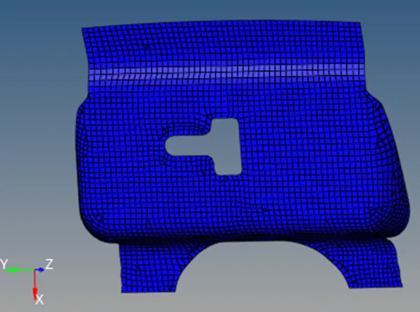
- Check the final quality parameter by
Select second model for mesh
Hinge
The given solid model is:
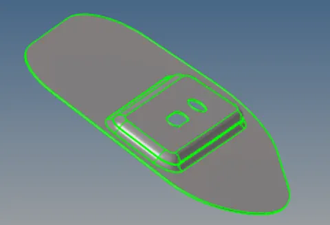
- Firstly we do autocleanup the model by (Geom< autocleanup < surfs < autocleanup)
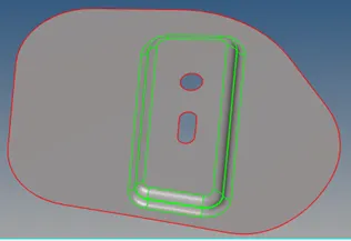
3.Split surface as above method for easy mesh creation
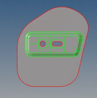
4.Create automesh and final mesh with Quality parameters is
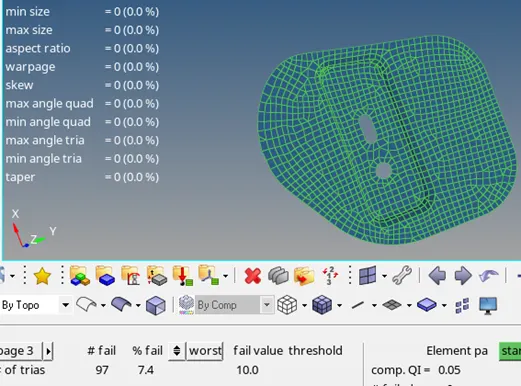
- Create mid point by (Geom < nodes< Interpolate node ). During selection of interpolate node . select the nodes of circular centre nodes of both hinge.After create one node will generate between these two node

- Reflect the mesh by (Tool < Reflect < Element (displayed) < y-axis < Base (mid point in above red boundry)< reflect.
7.After reflect
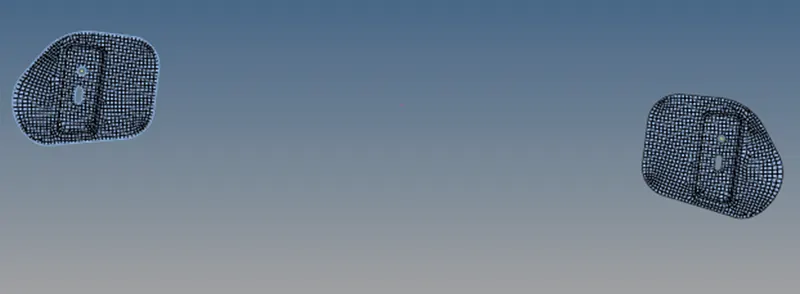
Select other model
Inner extract model
Given model
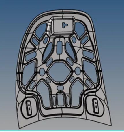
2.Create mid surface
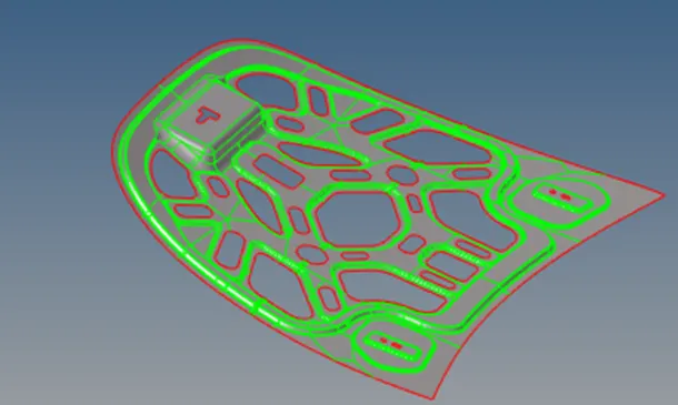
3.I split the model as similar to symmetry by (Geom< Quick edit < split surface nodes (select the nodes along the model). And I split the model as look like below
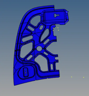
4.Create split line by quick edit command and Create automesh.
- I find the some detached element
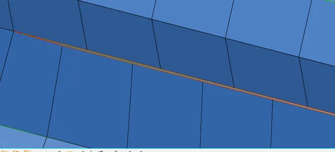
- This problem can be solved by deleting one layer element
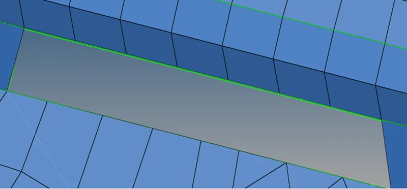
6.Create re element by ruled option ( 2D < Ruled < node list (select upper nodes of element ), node list (select lower nodes of element) < Drag Mesh W/o surface < create).
7 Now check the unconnecting edges of element by (Tool < edges < elems < find edges)
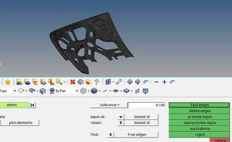
- Reflect the mesh and check the preview equivalence by (Tool < edges < preview equivalence then select equivalence option to connect the reflect element edges).
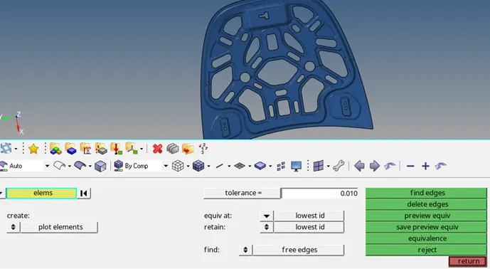
Select the other model
Outer extract model
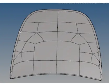
2.Create mid surface and split as symmetry and also split the surface for easy mesh.
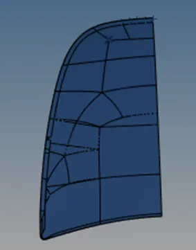
3.Create auto clean up an specially cleanup the heming edges by toggle
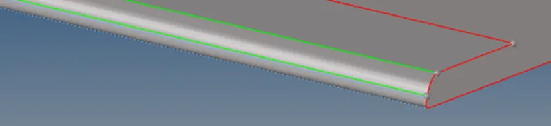
After the toggle edges
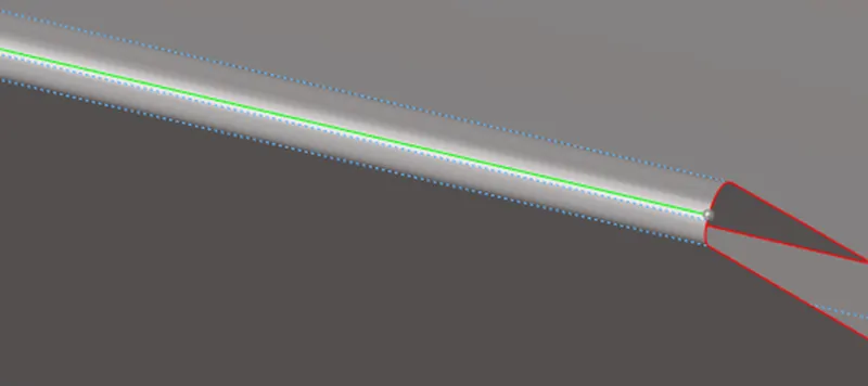
This toggle of edge is needed otherwise the element formation of heming portion will be less size as compare to small element length.
- Create automesh and check the Quality result.
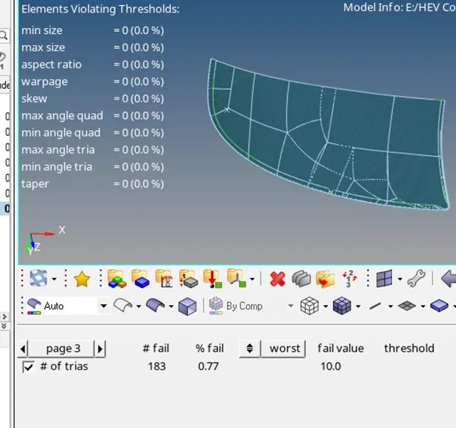
- Reflect the element by creating dublicates element and check the element connectivity by (edges < element (displayed) < preview equivalence)
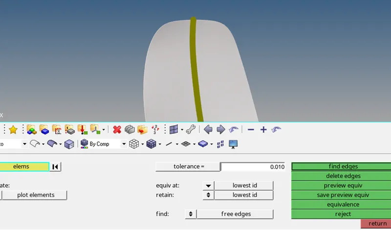
5.Create equivalence and check element quality criteria.

Result and Discussion:
All models fullfill the given quality criteria.These all models are checked with all element connectivity .If the connectivity will not proper then there will be a wrong result in simulation.
So Quality criteria shhould be properly full fill with all element conectivity.