Week 6 - Creating connection for Rear door
Aim:- Creating connection for Rear door
Objectives:-
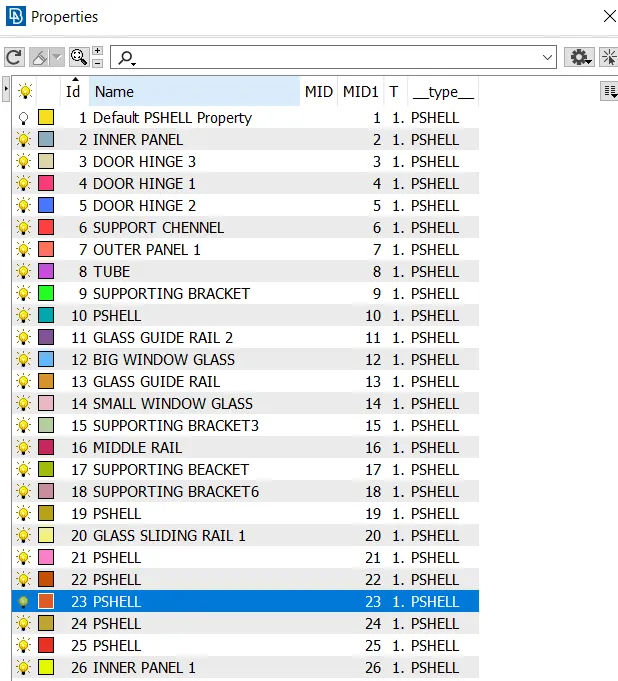
- To create and apply different PIDs for different components.
- To perform suitable connection.
First import the model
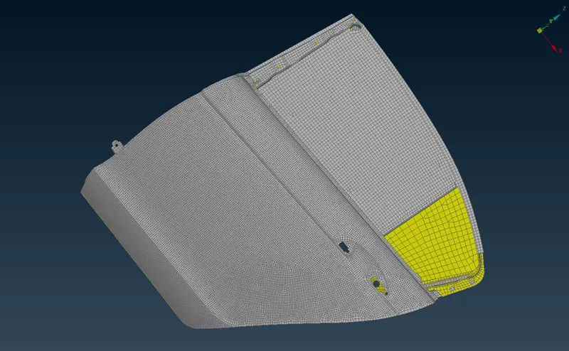
Define PSHELL Properties (PIDs):-
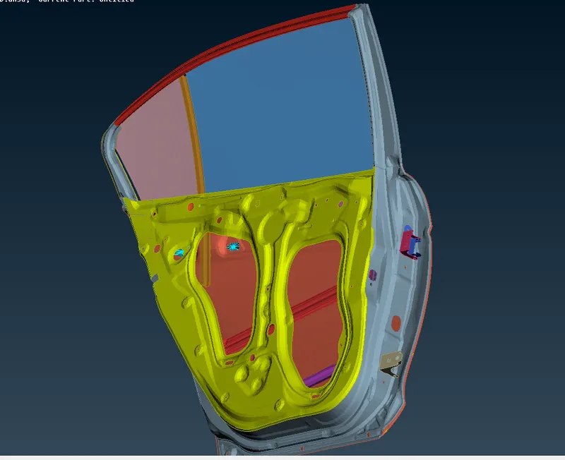
- Define the properties of various components for the rear door model.
BOLT CONNECTION:-
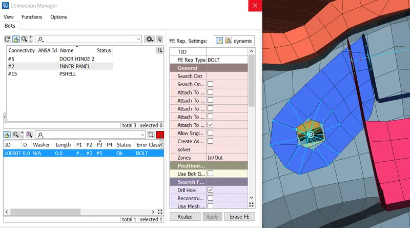
- The hinge parts connected with the bolt connection.
- Because the door is pivoted at the hinge and should move along the particular fixed direction, so we need to removw the rotational axis in whichthe door should not move.
- In order to define the bolt connection for the hinge region, the degree of freedom should not be restricted to all degree of freedom.
HINGE REGION EXPLANATION:-
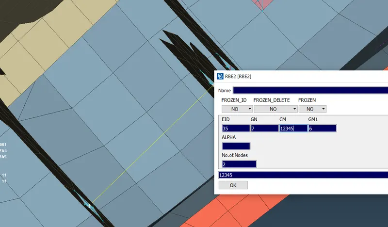
- After creating the rigid connection at the hinge parts need to be joined with a 2 node RBE2 connection created under Nastran Deck.
- In order to define the bolt connection for the hinge region, the degree of freedom should not be restricted to all degree of freedom.
- Here the rotational Z-axis (6) is restricted with respect to the global axis for the hinge region so that the door restricted only 2 axis.
CLUSTER RBE2 DEFINITION:-
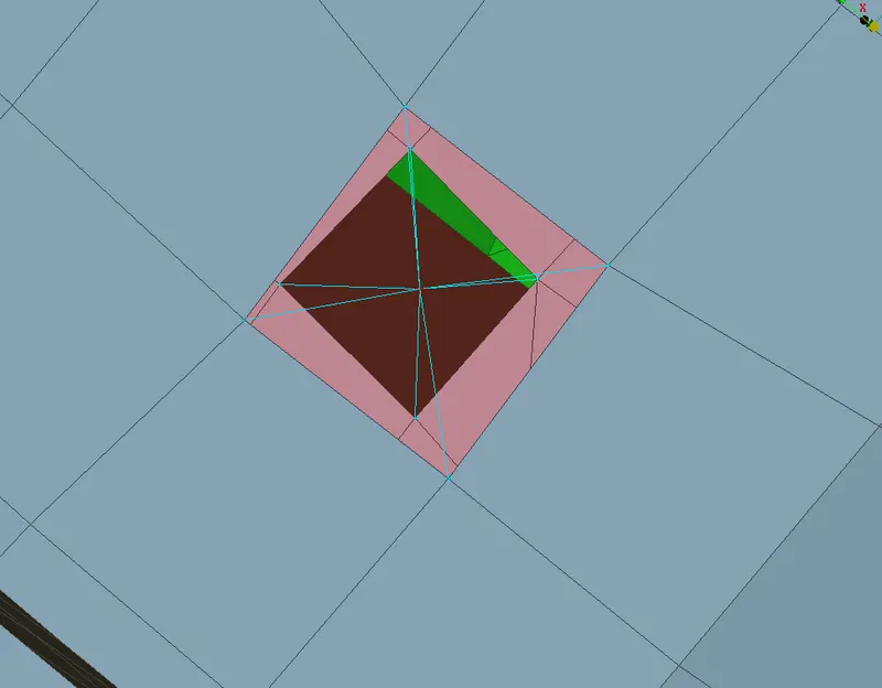
- In order to join some of the rigid parts that tend to join we generally ue cluster many RBE2 Nodes for connection to define it.
- This forms a rigid connection over 2 parts.
INDIVIDUAL CONNECTION:-
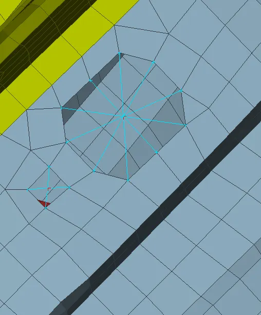
- Individual holes are given zone cut under Mesh Deck then making it rigid connection with many nodes RBE2 in order to gain the extra strength at the particular region.
SPOT WELD CONNECTION:-
- Some parts where the bolt or rigid connections are not possible need to be welded.
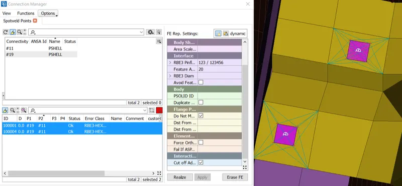
- In order to do so, i created a spot weld and by using the convert tool changed it to a spot weld point.
- By selecting the spotweld point and defining it into connection manager was able to create a spot weld region across 2 componenets with the help of RBE3-HEXA-RBE3 connection.
- Create a spot weld PID of solid which determine the material of weld.
RBE2 CONNECTIONS FOR DOOR HANDLE:-
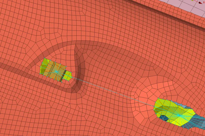
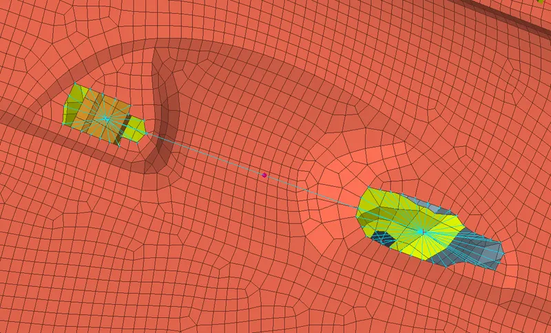
- In this type of RBE2 connection, we provide connection in the door handle by providing the spider connections of two holes of the door handle and then connecting the two master nodes of the two spider connection to form a centroid or COG as shown below in the image.
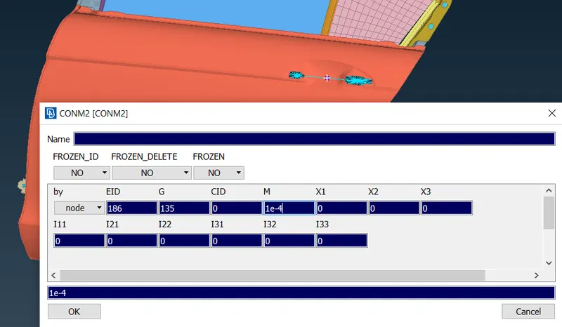
- Then provide the Con mass for the COG point using the Nodes option present in the CONM2 in CONMI option in the elements tab in the NASTRAN module. Then in the tab , we provide the COG mass as 100 gm.
WEATHERSTRIP CONNECTIONS:-
- In this type of connection first, we make the curve from the window which include the fixed one near the C pillar and the sliding window or the main window using Feat2Curve option present in the Perimeters tab of the Mesh Module then we convert the curve into spot line using Convert option.
- The bottom spot line is projected the other line using transform option.
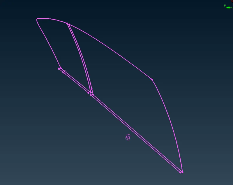
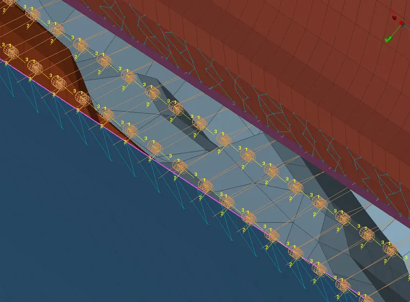
- Define the spot line as RBE3-CBUSH-RBE3 elements as it the best to define the bush elements and each bush elements have the stiffness along the 3 axis.
- Once we realize the elements, a number of CBUSH elements are formed across the spot line.
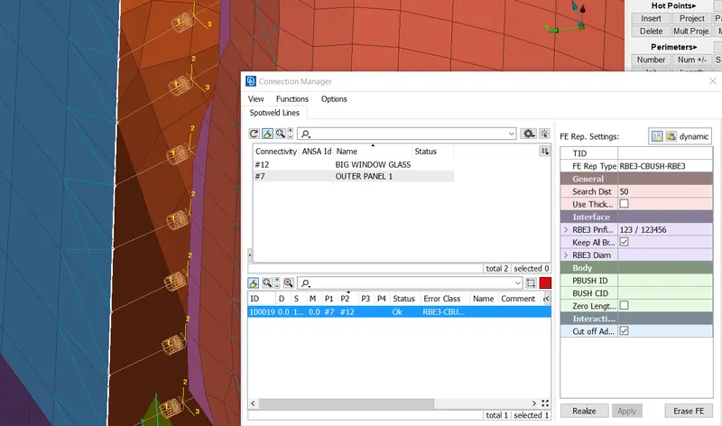
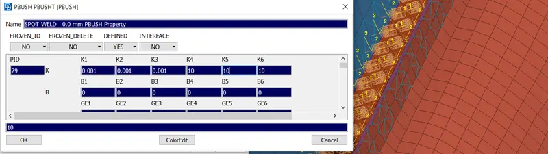
- The bush ID is created and the enter 6 stiffness values K1, K2, K3, K4, K5 & K6.
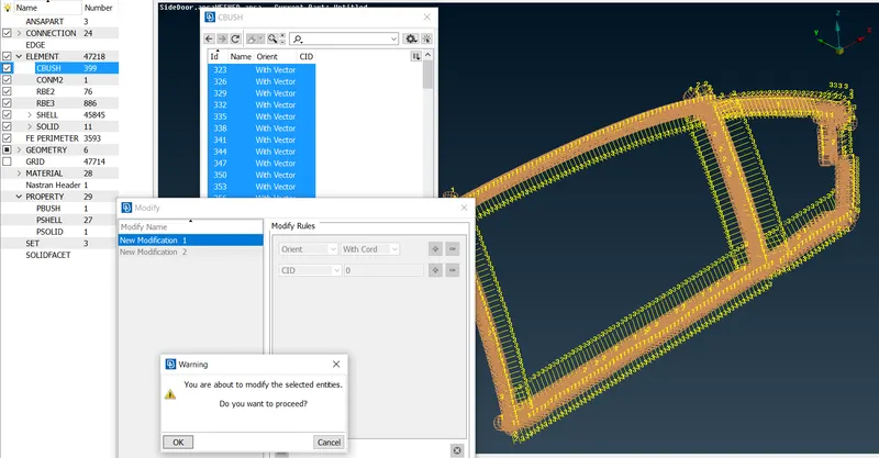
- All the CBUSH elements formed need to be aligned with the global coordinate by making one axis 0 so that it will be aligned with the global axis of the vehicle.
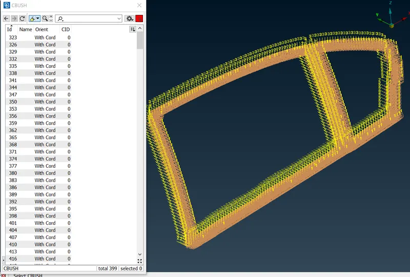
- Finally, we obtain the CBUSH connection as shown in the below image.
RESULT:-
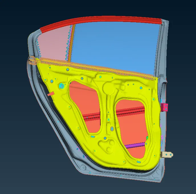
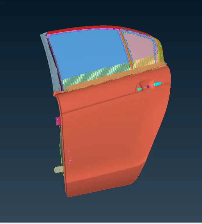
- Finally, all the connections are successfully deployed for the Rear Door Assembly.
LEARNING OUTCOME:-
- Learned about different types of connections and deploying them with a particular region.
- Spot Weld, CBUSH, Bolt, Seam Weld, Rigid Cluster are some of those connections.
- Door Handle connection determining the MASS of it.
- Latch and Hinge region
- Fixed and movable glass window.