Week 6 - Creating connection for Rear door
AIM: - ADD APPROPRIATE CONNECTIONS TO THE PROVIDED REAR DOOR FE MODEL.
Objectives:
Connect the FE model through appropriate connecting elements.
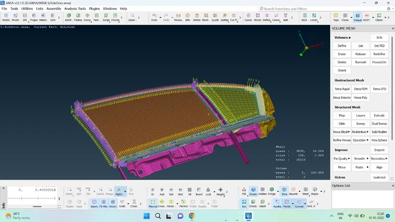
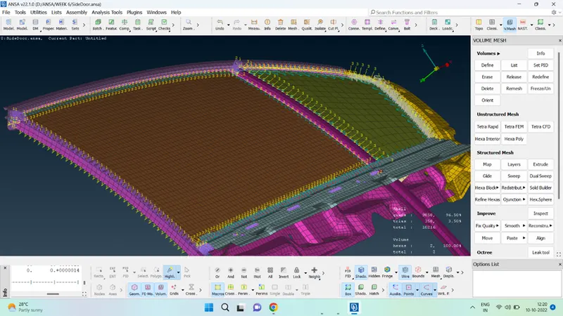
The present challenge was completed using the ANSA tool. In this challenge, the FE model is connected using different connection elements like RBE2 elements, BOLT joint, SEAM WELD, SPOT WELD, and BUSH connection. The steps involved in doing so are as follows:
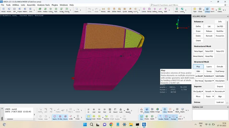
STEP 1: Import the model and assign different PIDs to components.
The model of the rear door in the ANSA tool looks like this:
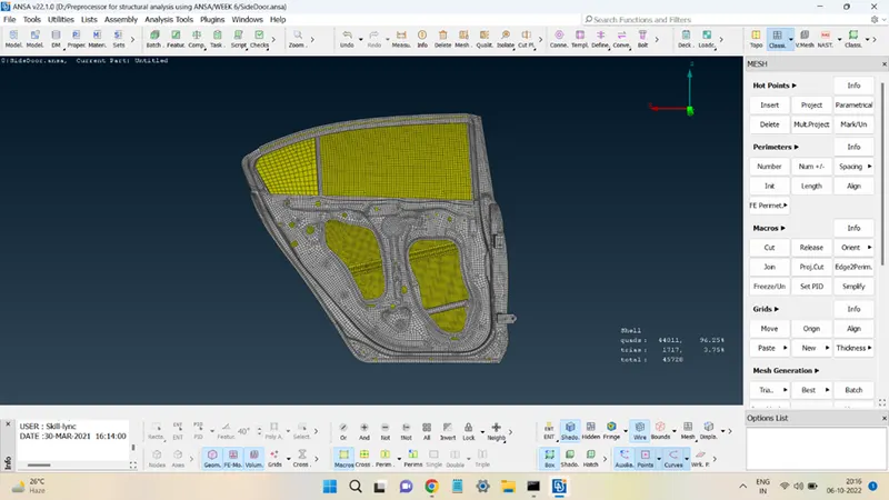
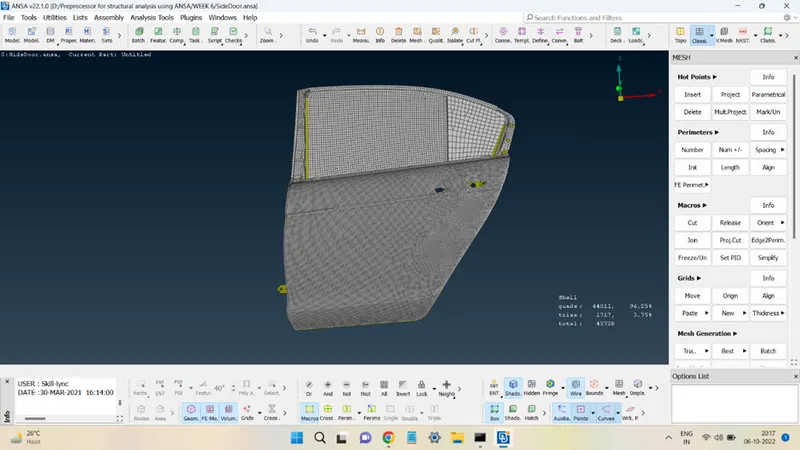
The parts of the model were assigned different PIDs for better understanding and clarity. The model, after PIDs are assigned, looks like this:
STEP 2: Adding RBE2 and Bolt joints.
RBE2 link is a joint that has all the 6 DoFs restricted, thus an RBE2 joint represents a joint fixed in space.
Similarly, the Bolt joint is also a joint that may have all its DoFs restricted.
In ANSA these RBE2 can be found in the ELEMENTS panel present in the NASTRAN deck.
Hold the left click over the RBE2 option the drop-down list will show the ways of creating these links.
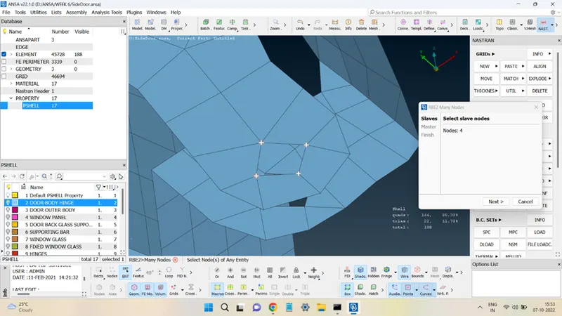
Many Nodes connect multiple slave nodes into a single master node. Two Nodes connect 2 master nodes.
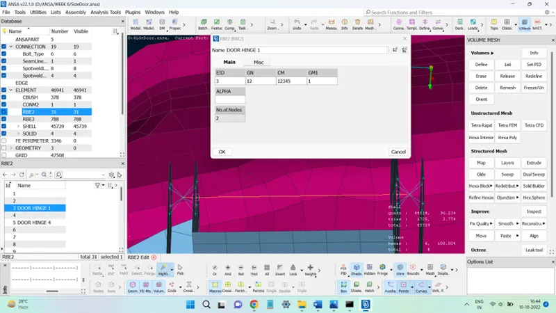
In the many nodes method, select the slave nodes, click on Next then the master node will be generated in the center. In the window, the number present in front of CM tells the total restricted DoFs of the master node obtained, as shown below:
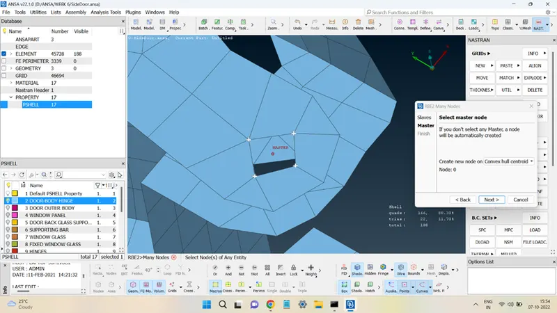
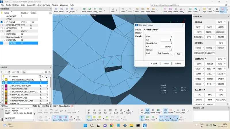
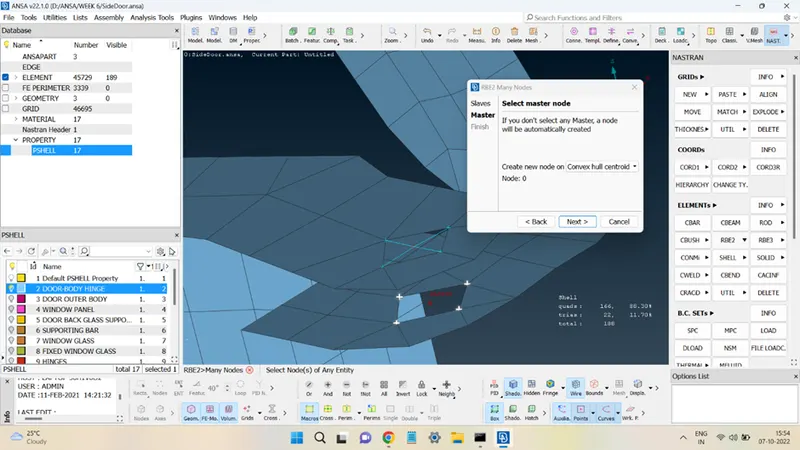
Similarly, another RBE2 master node was created for the below hole, as shown below:
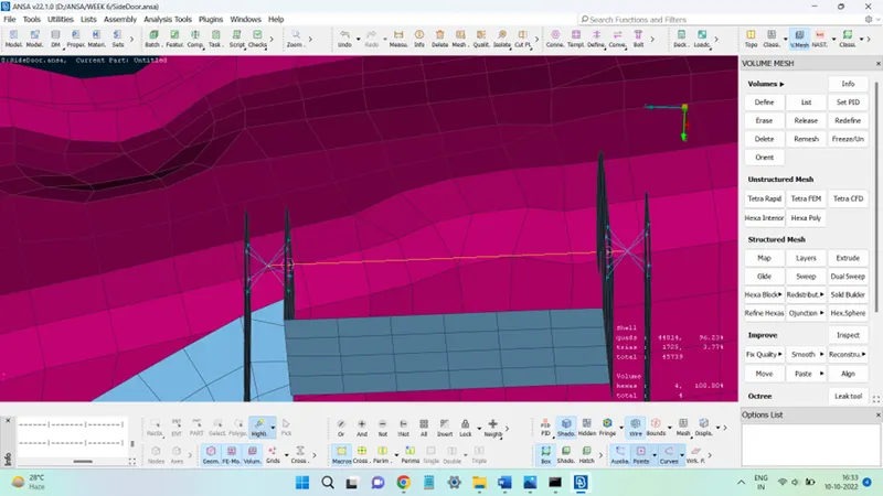
These two master nodes were then connected using Two Nodes method to get the bolt joint, as shown below:
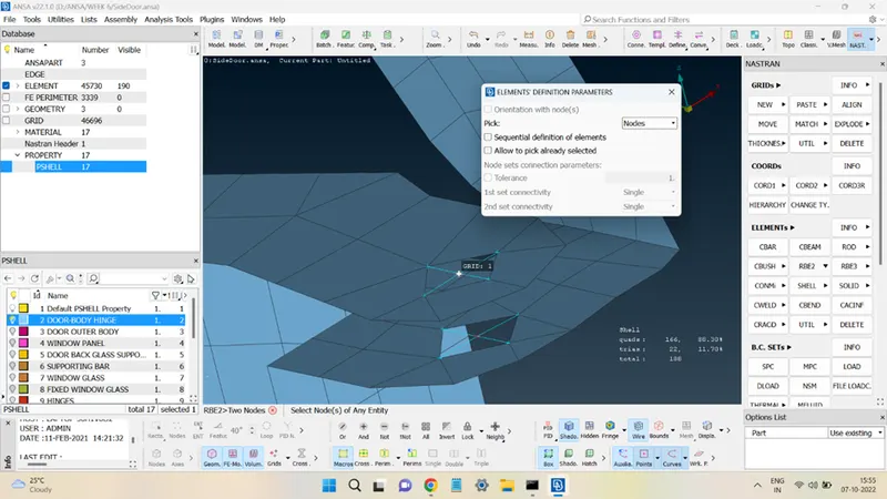
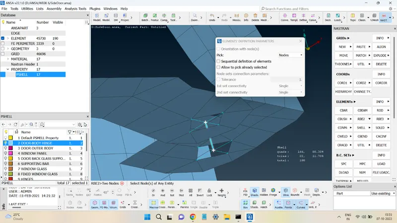
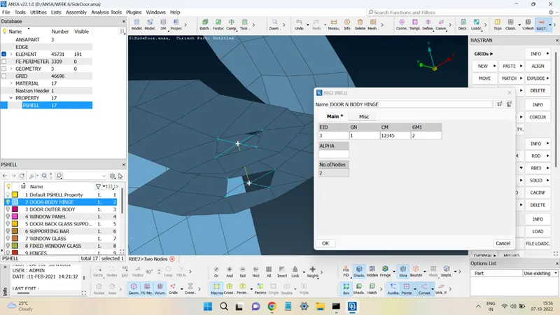
Since the above joint is a hinge joint between the car body and the door, therefore to have the door be able to move one rotational DoF of this bolted joint is kept free. This is done by entering the number in front of CM as 12345 instead of 123456.
The other method to create a bolted joint is to:
First, create a 3D point at the COG of the hole.
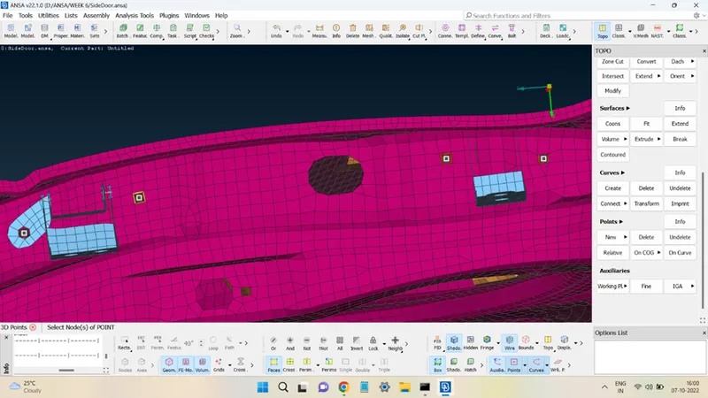
Convert the 3D point into Bolt connection type.
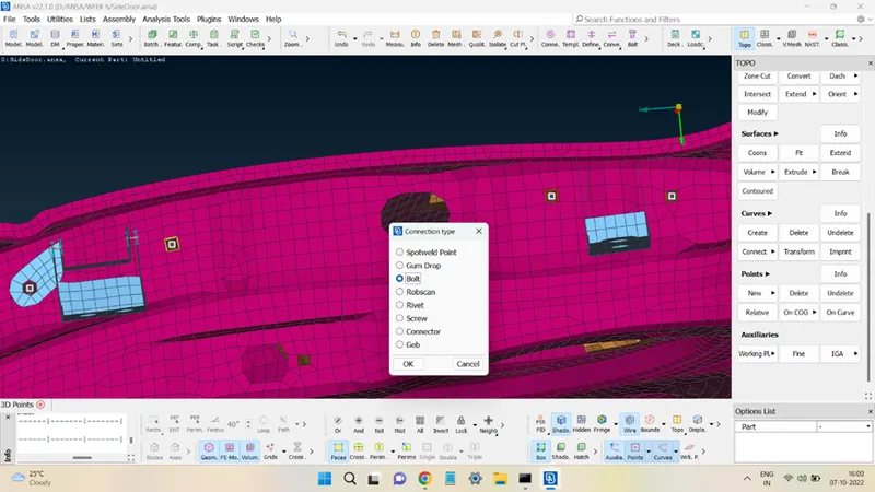
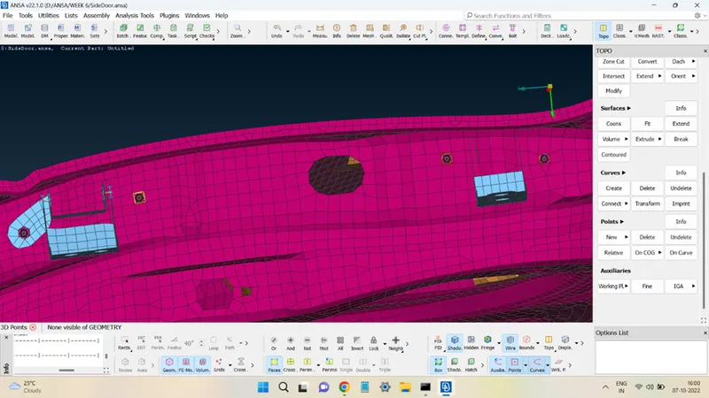
Open Connections Manager, present at the top, select the bolt point then middle click.
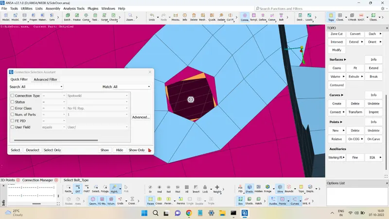
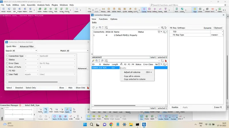
In the P1 option, right-click and then click on Modify followed by pressing the F1 key. This will open the PID window to select the component to be connected.
Choose the component to select OK and press ENTER to confirm.
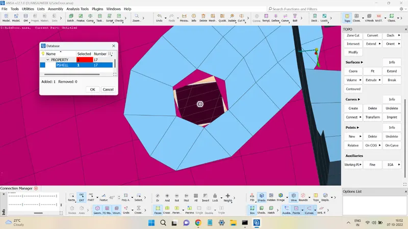
Similarly, do the same for P2 and press ENTER to confirm. In the above example, 3 layers of the components will be connected using this bolted joint. In such cases, generally, the P1 accommodates the plane in which the bolt point is present and the rest planes are accommodated in P2.
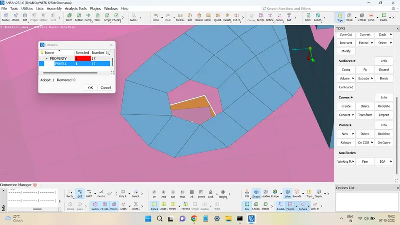
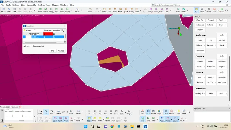
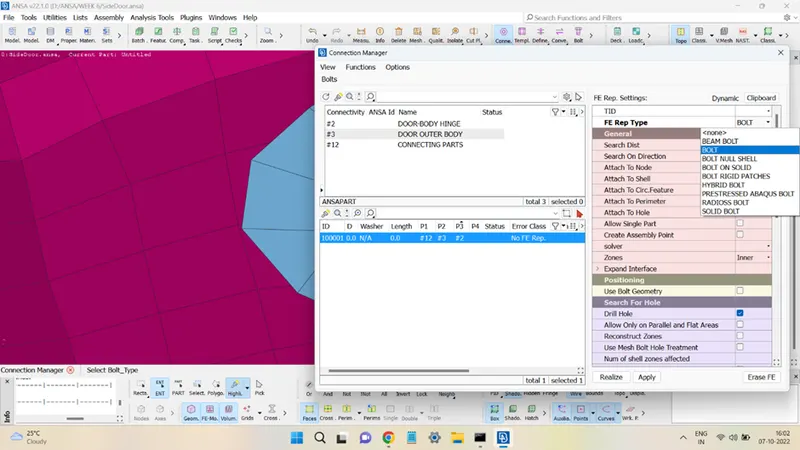
In FE Rep Types select BOLT.
Enter the appropriate value for the Search Dist to allow the algorithm to locate the nearby holes.
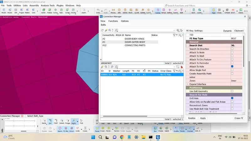
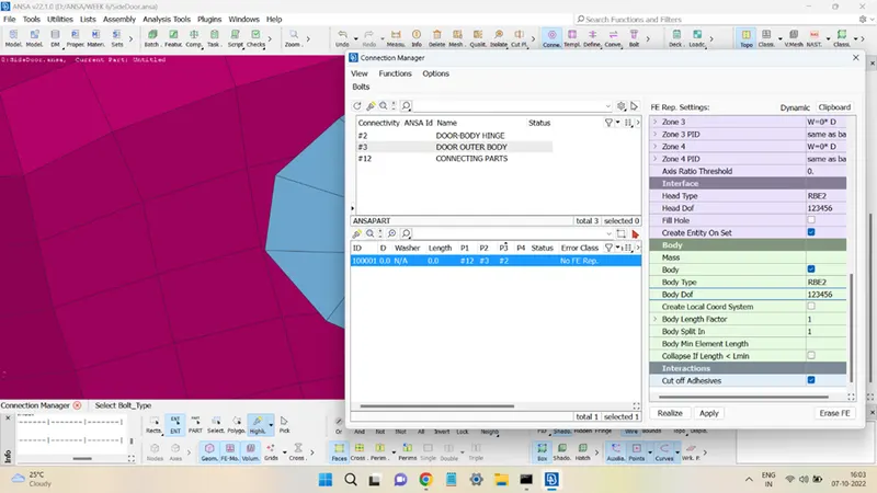
Click on Apply and Realize to generate the bolt connection.
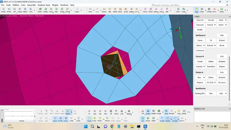
In the same way, the other bolt joints were obtained, as shown below.
In the above example, while defining the bolt properties if the Body options are left unchecked then the joint will still be bolt joint, however, now the bolt body won’t be represented and all the slave nodes will be connected to a single master node, as shown below:
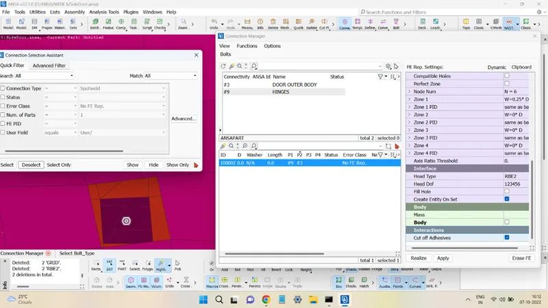
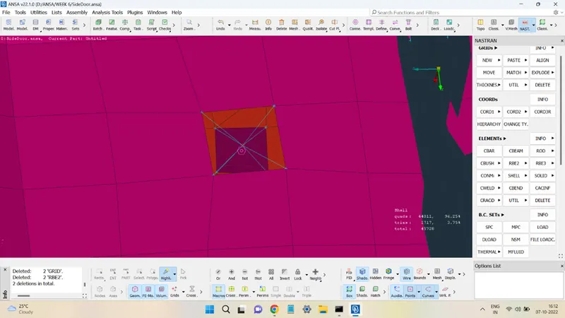
The door and body hinge joints were added through the same method and with 5 DoFs restricted.
STEP 3: Adding door handle mass element.
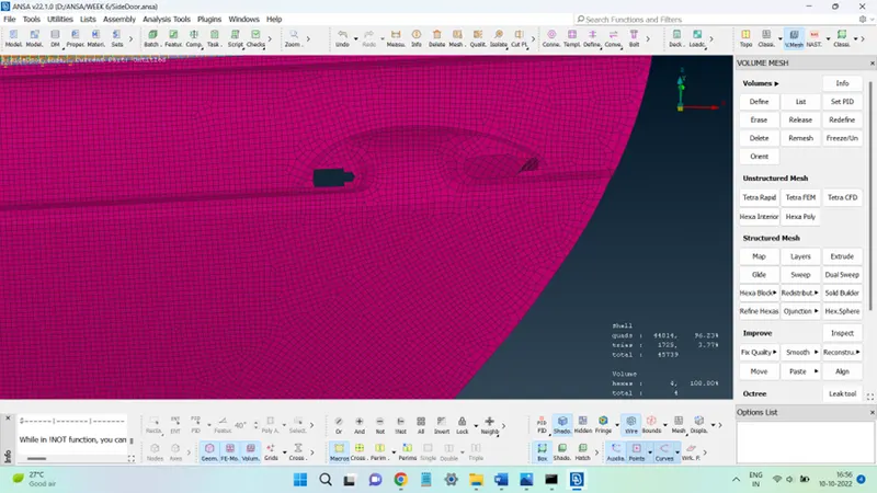
The door handle is shown in the figure below.
First, two RBE2 master nodes are created around the two cavities, shown in the figures below.
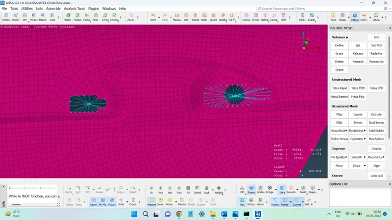
These two master nodes were connected using the RBE2 element.
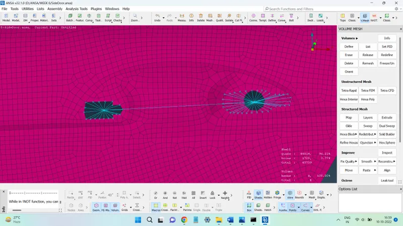
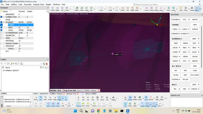
Finally, a mass element is added at the center node. The mass element in ANSA is represented by CONMi present in the ELEMENTS panel of the NASTRAN deck. Go to CONMi and left-click and hold for the drop-down window to show and in that select CONM2. Again, hold left click on CONM2, and choose the option Nodes.
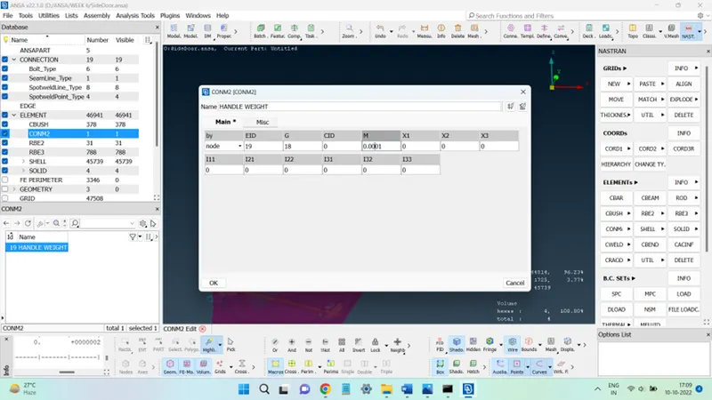
Select the center master node and give a middle click. A window will pop up, add the mass value under the option M.
Point to Remember: The default unit for mass taken up in CONM2 is Tonnes, so add mass having unit as tonnes carefully.
STEP 4: Seam Weld connection.
The two parts shown in the figure below can be connected with help of either a Spot weld joint or a Seam weld joint. For this challenge, the connection here is made using a Seam weld.
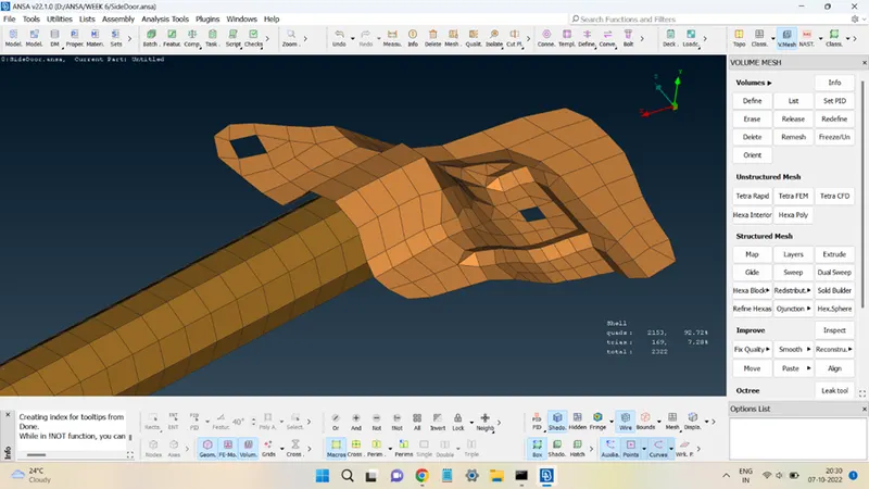
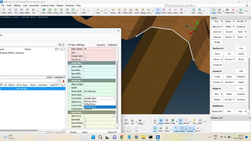
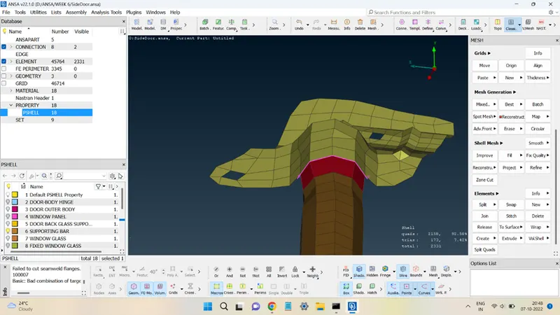
To create a seam weld, first, a seam line must be created. This is done by first converting the Con to a curve and then this curve obtained is further converted into a seamline and then this seamline is used to create a seam weld joint between the parts.
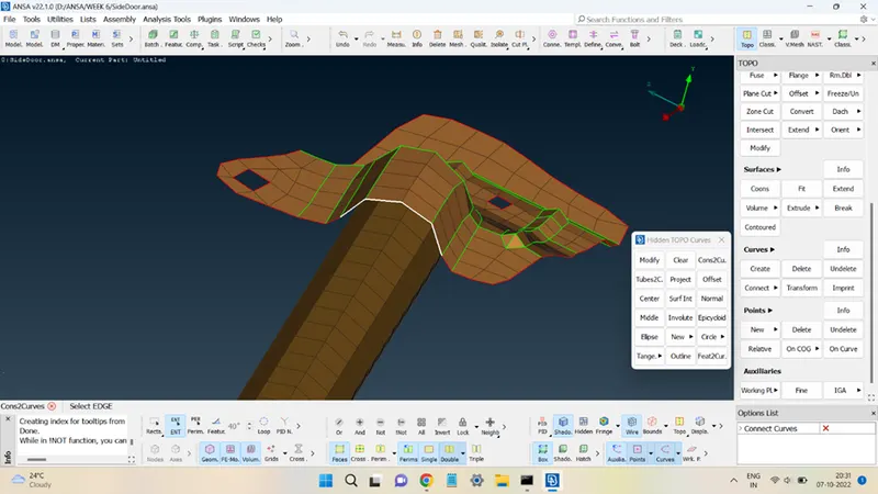
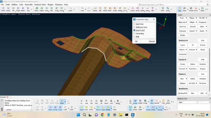
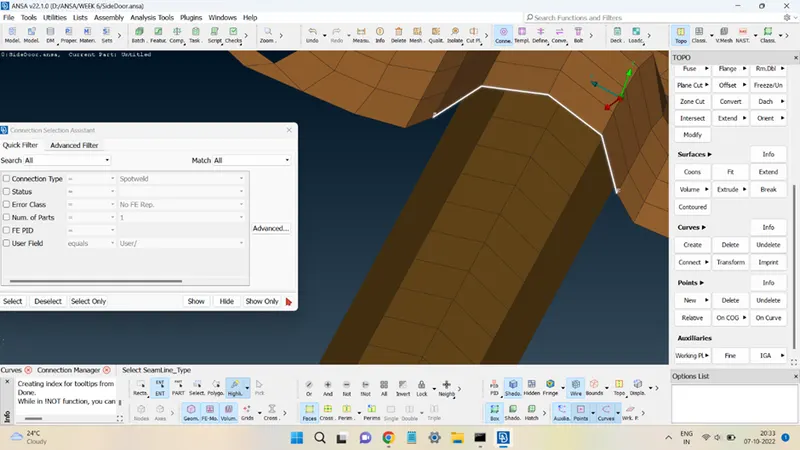
Add appropriate surfaces in P1 & P2 columns and FE rep Types choose OVERLAP-SHELL.
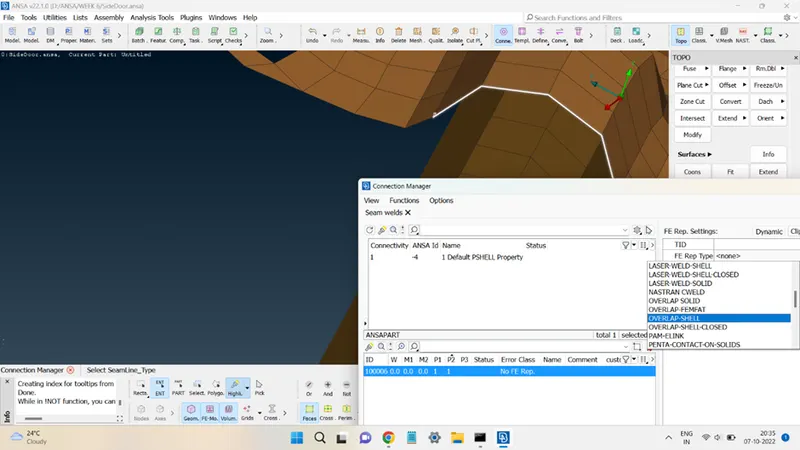
In the Root Shell option choose Double Row and click on Apply and then Realize.
STEP 5: Creating Spot Weld connections.
A spot weld connection will be established between the two parts shown below.
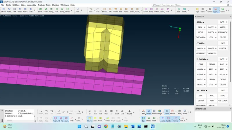
First, create a 3D point at the spot weld location.
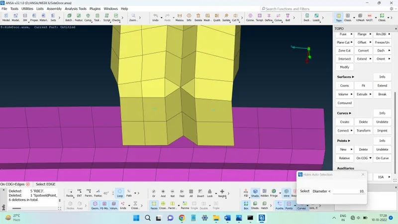
Convert the 3D point to the Spot Weld point.
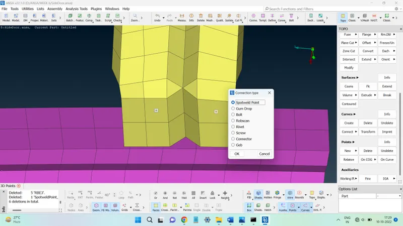
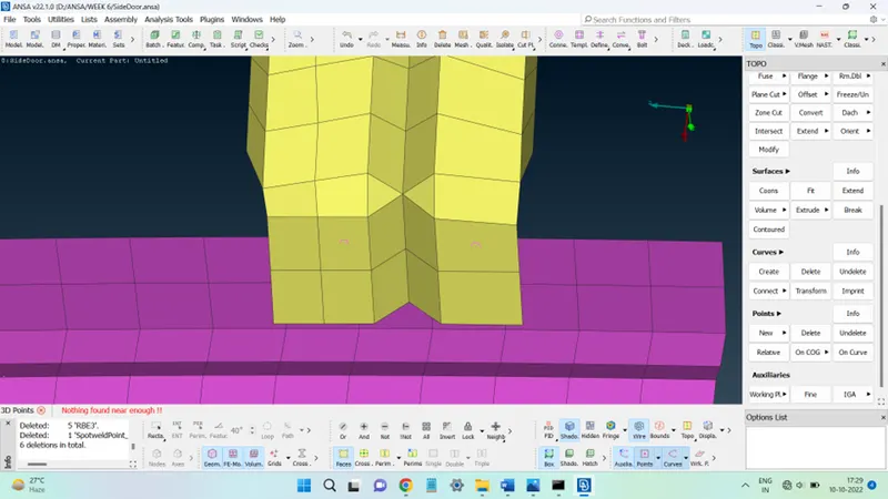
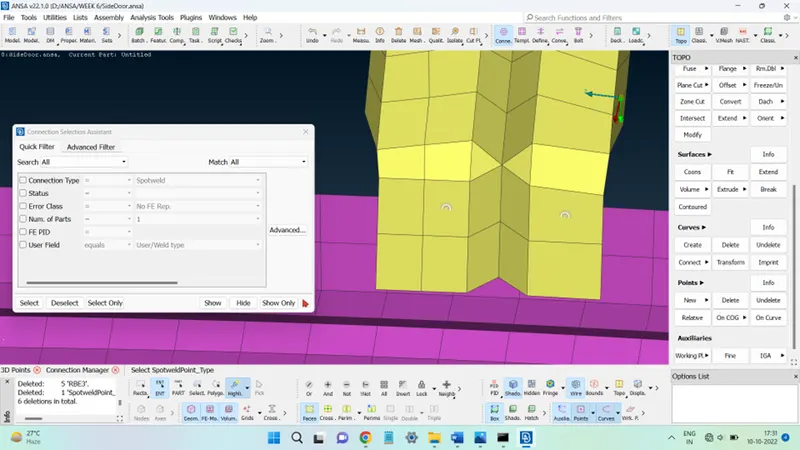
Open the Connections Manager, select the Spot weld points, and add appropriate surfaces under the P1 and P2 columns.
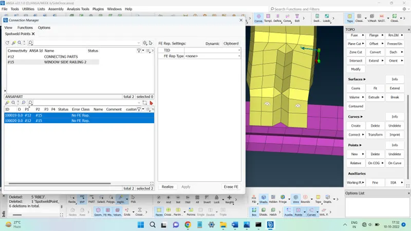
In the FE Rep Types select RBE3-HEXA-RBE3. Add the appropriate value of the Search Dist and for RefC Pinflags change the value from 123 to 123456. Click on Apply and then on Realize to finish.
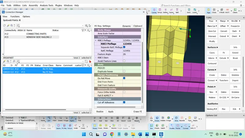

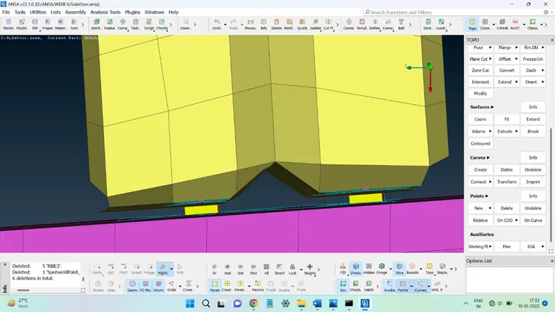
In the same way, the spot weld was obtained at the other location also.
STEP 6: Adding weather strip connections around the window glass.
In the car doors, around the glass, a black colored strip is present which provides a cushioned enclosing joint of the door. This joint in ANSA is modeled with the help of a CBUSH element link.
To obtain this connection, first FE is converted to curves and these curves are further converted into Seamline.
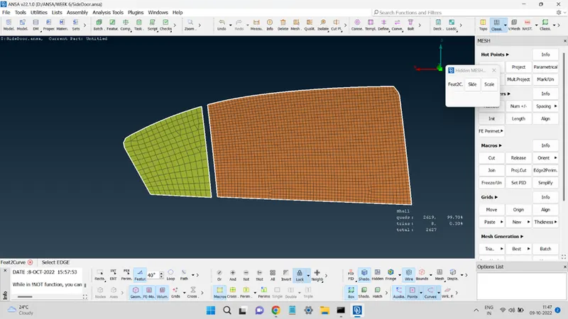
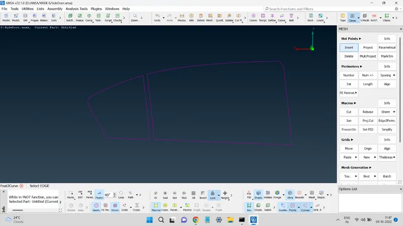
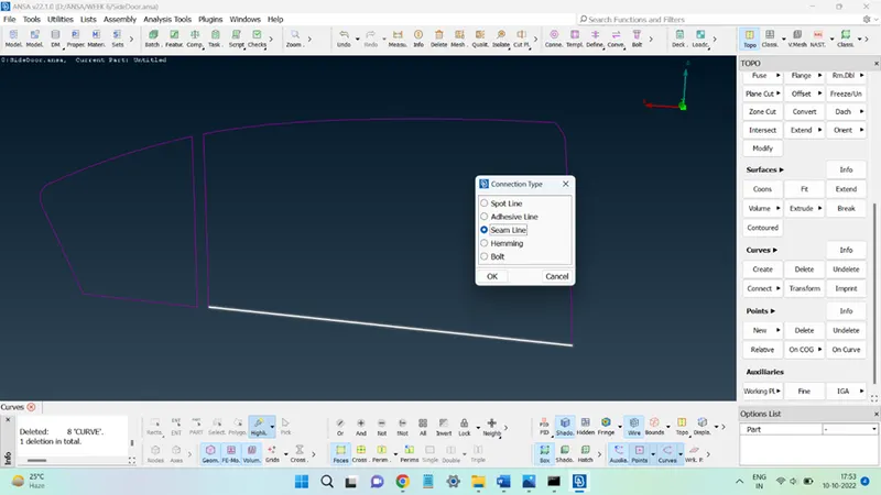
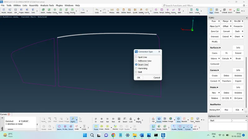
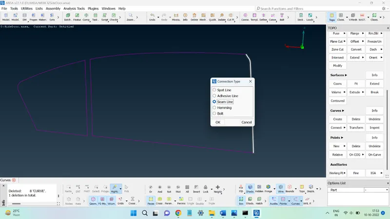
Now, open the Connections Manager, select the seamline one at a time, and correctly select the surfaces under the P1 and P2 columns.
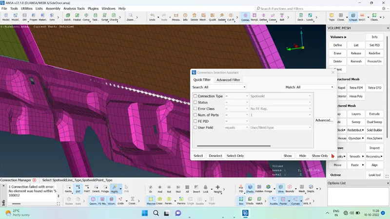
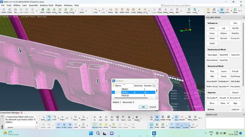
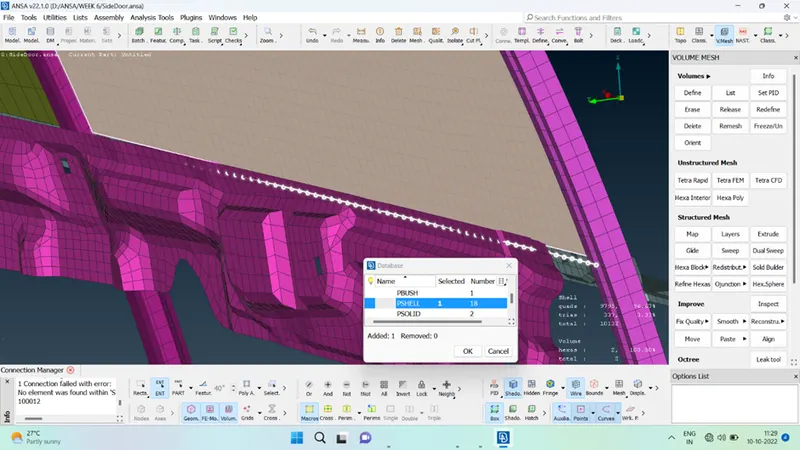
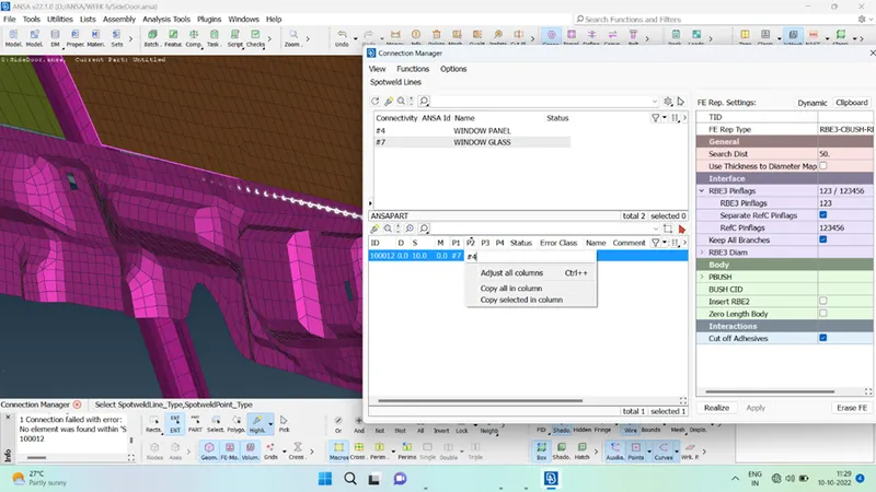
Enter the value below the Spacing column as 10 and for the FE Rep Type choose RBE3-CBUSH-RBE3, add a suitable value for Search Dist, and in the check box in front of keep All Branches. Click on Apply and then Realize to generate the connections.
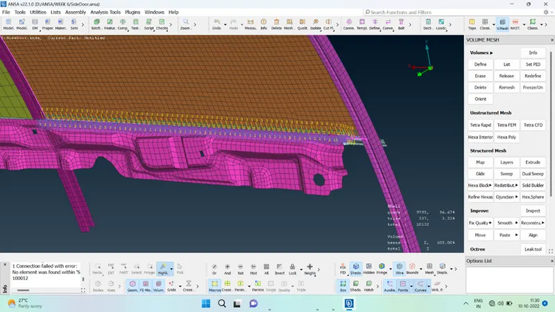
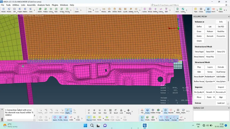
Similarly, the connection for the remaining seamlines was made to complete the weather strip connection around both the window glasses.
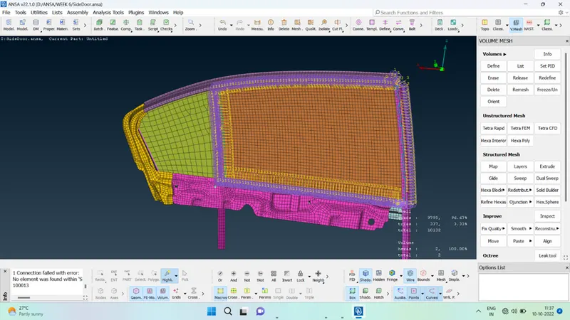
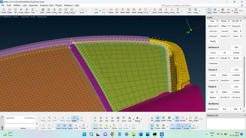
Next, all the links must be aligned in the same direction. To do so, two modifications were made to all the CBUSH links.
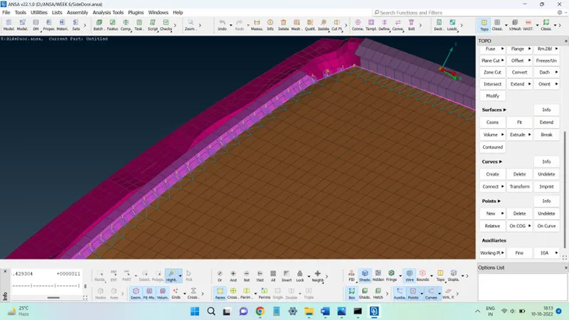
First, select all the CBUSH links, right click and select Modify. Search Orient in Modify rules and select it from the search results. Choose With the Cord option in the next column.
Next, add another modification, having the rule name as CID, and in the next column enter the value zero. This value represents the ID assigned to the global coordinate system, thus all the CBUSH elements will get aligned along the global coordinate system.
Conclusion:
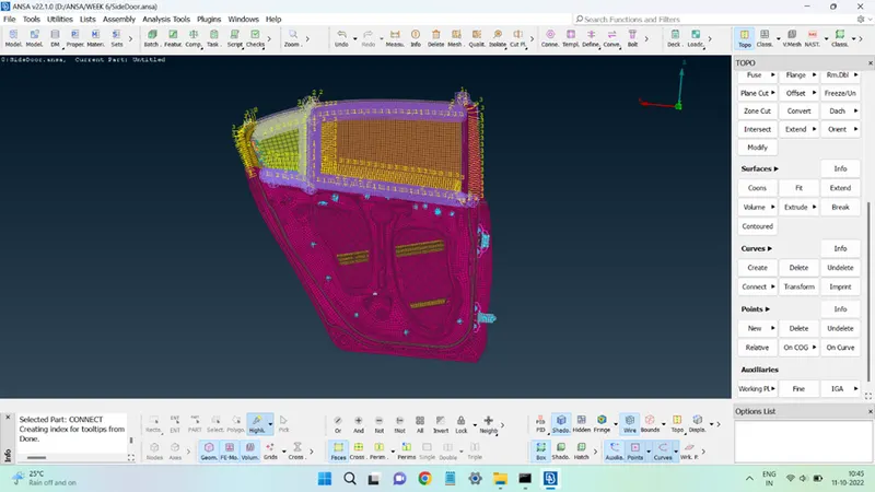
The connections were successfully added to the given FE model.
Learning Outcomes:
This challenge provides the opportunity to learn how to:
Add different types of connections between various FE parts.
Learn about the process of creating the elements and connections.
How to apply the connections and how to realize them.