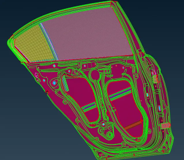
Week 6 - Creating connection for Rear door
Aim- To deploy connections in the FE model of a car side door.
Procedure-
1. Make different PIDs for the different components of the door. Every single unconnected component is given a separate PID.
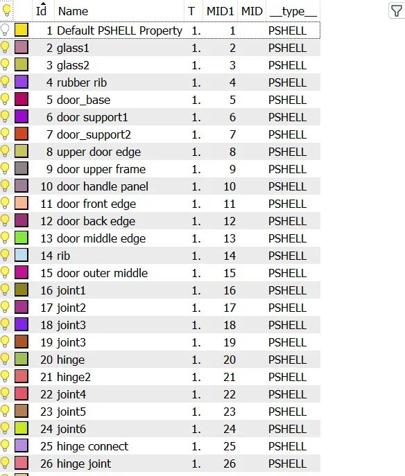
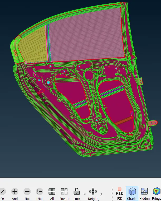
2. Give RB2 and cluster RB2 connections for required holes and near components.
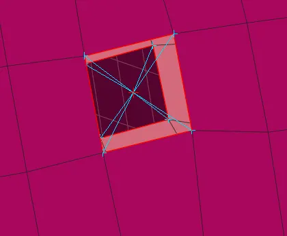
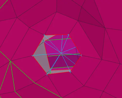
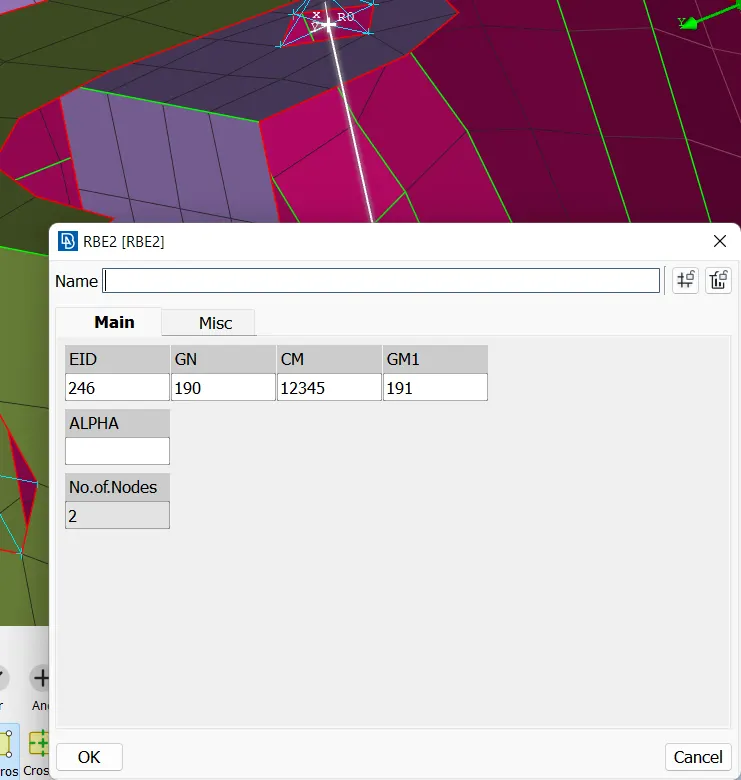
3. create the hinge connection as shown in the figure. make two RB2 multi node elements and connect the two elements with an RB2 two node element. Go to info elements and select the 2 node RB2 and free one degree of freedom door rotation about the hinge.
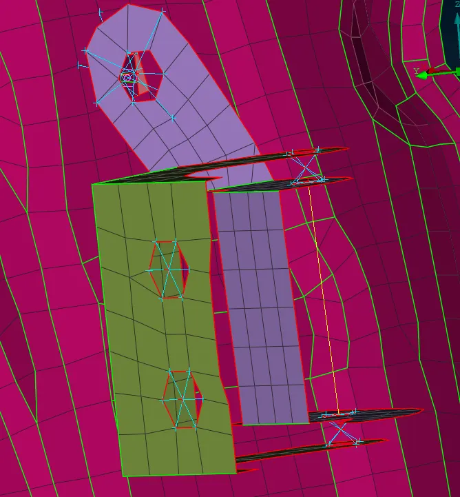
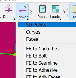
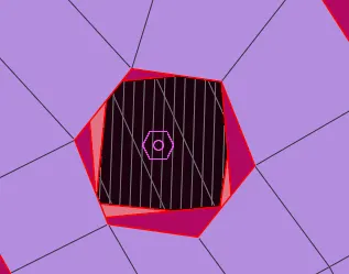
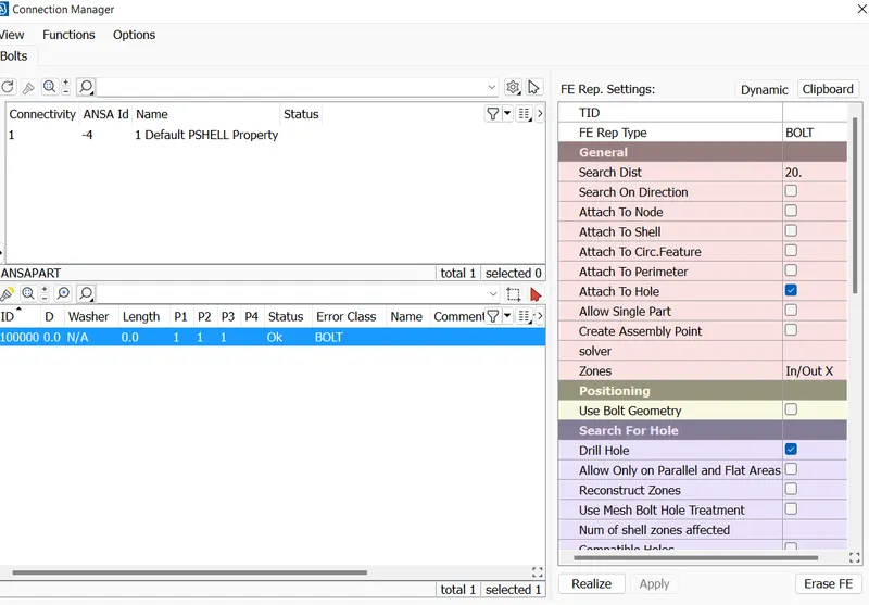
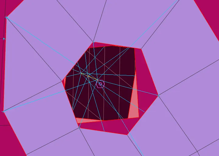
4. Go to Topo-> Points-> COG and create a point on any of the holes in line. Go to convert 3D point and convert the selected point into Bolt. Select the bolt and select the appropriate parameters in connection manager.
5. Create points on suitable metal components which are near to each other. create a point at that place. create spotweldpoint in convert option. check that the RB3 pinflag has all 123456 DOF constrained.
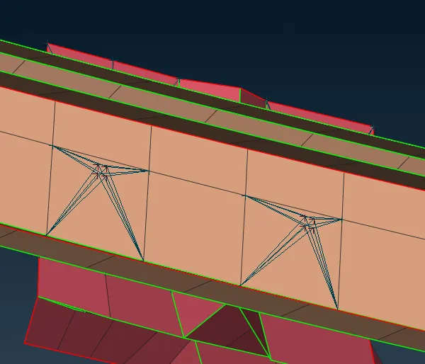
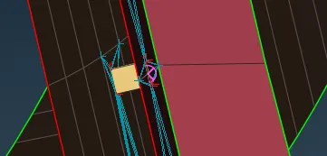
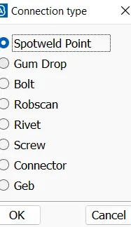
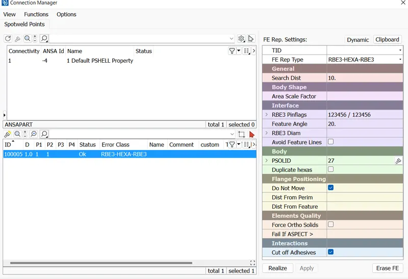
6. Similarly create other spotwelds as well.
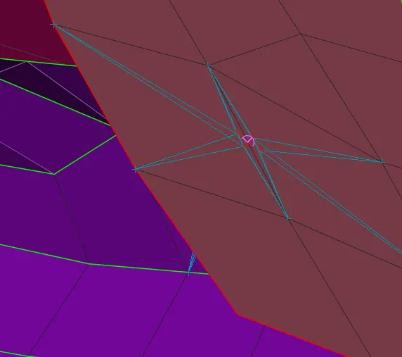
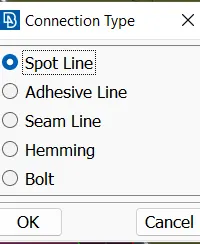
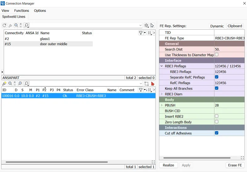
7. create curves using the glass boundary. Convert the boundary curve to spot line. select the spot line and create the CBush elements for all the glass boundary.
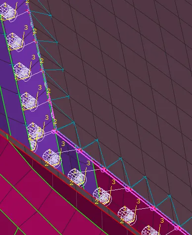
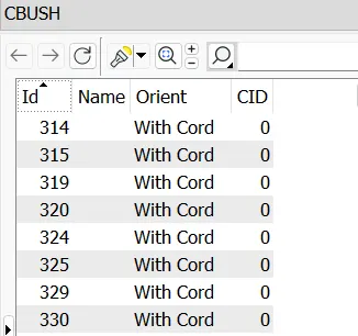
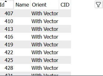
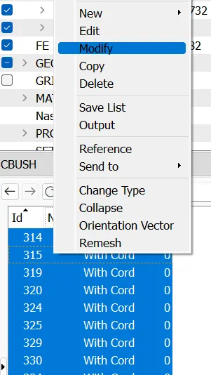
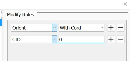
8. Go to elements-> CBush. Some CBush elements are aligned with the vector so to chage it select all and modify. Modify orientation as shown in the figure.
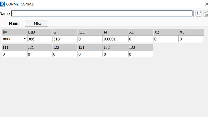
9. For door handle create cluster RB2 as shown in the figure and connect the master nodes of both the clusters. Select the middle node and give a mass of 100g at that node after converting to ton.
Learning outcome- Different connections were made and practised.
conclusion- The side door model connections were performed.