DEPLOYING THE CONNECTOR IN THE REAR DOOR
AIM :
To deploying the connectors properly on the given Rear Door FE model by using ANSA.
OBJECTIVE :
Assigning the property Identities for which each & every sub parts
Creating the RBE 2 1D element for which represents the bolts joint
Creating the RBE3 - CBUSH - RBE3 1D element for which represents the weather Strips.
Creating the RBE3 - Hexa - RBE3 element for which represents the Spot weld joint.
Creating the mass concentration element for which represents the door handle.
GIVEN FINITE ELEMENT MODEL :
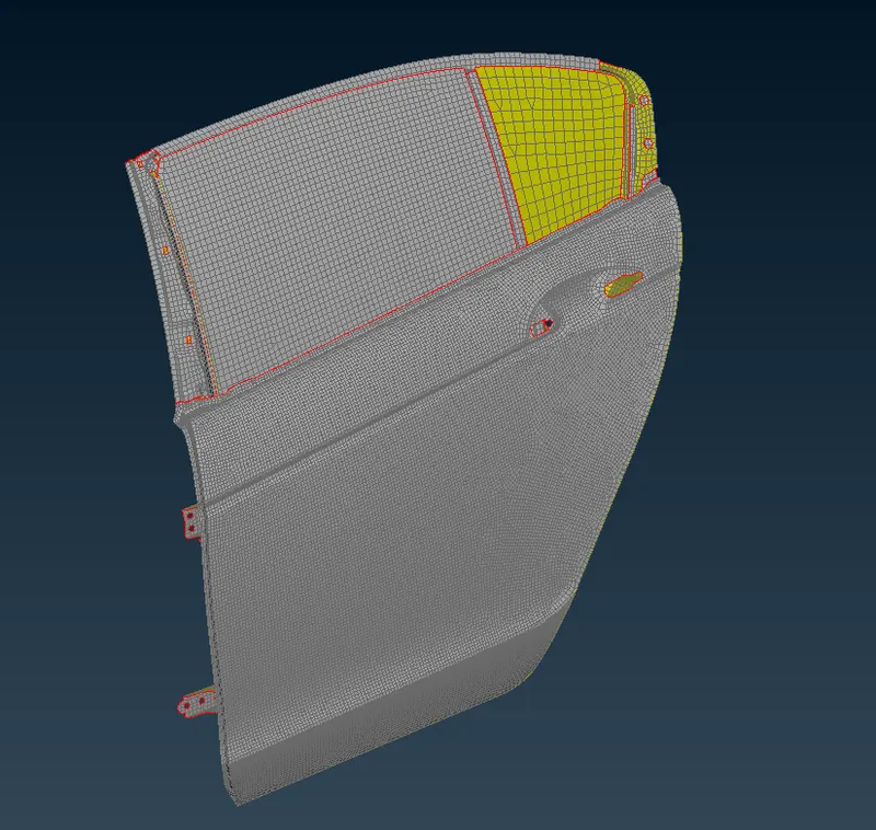
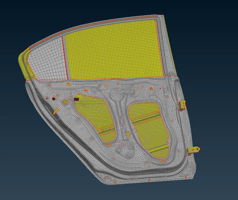
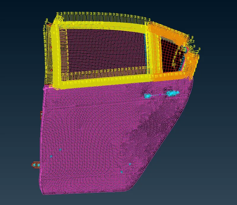
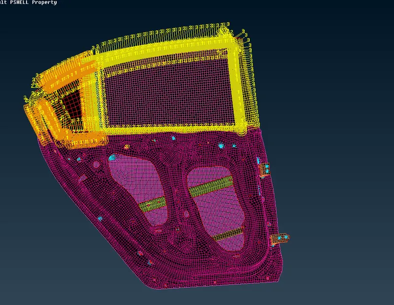
Open a ANSA software, a given FE model file type is "Nastran". Inorder to import the file, select the file at where tool bars location & followingly choose the input option and then select the nastran option to importing the appropriate file which is Rear door.
Rear Door from Outside View :
Rear Door from Inside View :
PROCEDURE TO ACQUIRING THE OBJECTIVE :
I) Assigning the Property cards :
Change into Property mode instead of Entity mode by using Draw mode gui option for which visualization purpose from the graphical window.
From the imported model, whole rear door model had been assigned by single property card. If whole component has assigned to single property card alone, we should not provide the part id's properly while we deploying the connector inbetween two parts.
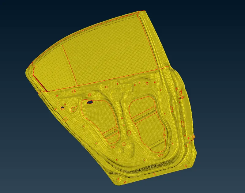
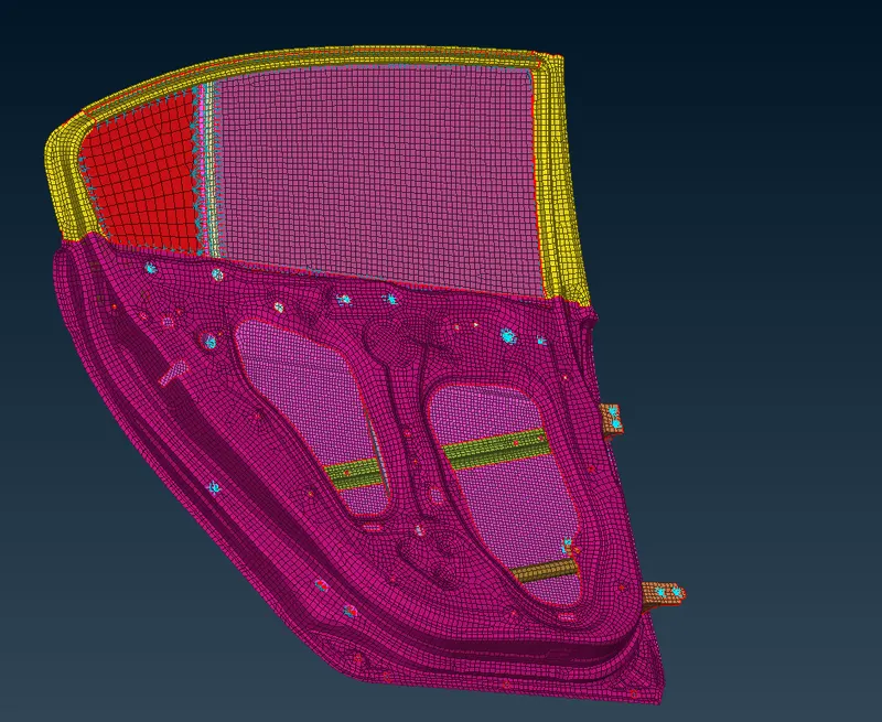
Inorder to avoid those issue while we deploying the connector inbetween the parts. First of all, We have to assigning the individual property cards to each & every subsytem on the rear door panel.
After assigned the property card to all parts, it has looks like as shown as below image.
II) Creating the RBE2 1D Element :
A RBE 2 is stands for Rigid Body Element type 2, basically it have infinite stiffness. To defines a rigid body whose indepenedent node degrees of freedom are specifiied at single point and dependent nodes degrees of freedom are specified at an arbitary number of points.
In this case, we use RBE2 1D Element for which represents the bolt holes & Rivet holes at whereever it's required.
Inorder to create the RBE2 Elements, we have select the RBE2 option under which Nastran deck module & Element sub modules.
We are creating the RBE2 Elements in two methods which are Cluster method and By using 3D bolt point.
i) Cluster method :
Select the RBE2 option under which Nastran module & Elements sub module.
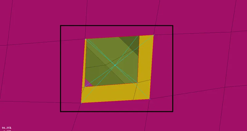
First of all, select the slave nodes which is dependent nodes and then followingly click the middle mouse buttom, it will automatically find the master location & create the node by itself which is nothing but a independent node.
When we use this method, it have multiple number of dependent nodes and only one independent node.
After creating the cluster type method, it will looks like as shown in the below image.
ii) By using 3D bolt point :
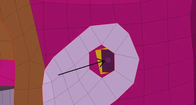
Create a COG point which is nothing but a center of gravity at particular selected location. Followingly, convert into bolt type point from 3d COG point by using convert gui option.
After creating into the bolt points, it will looks like as shown in the below image.
Click the connector manager, immediately one tab has pop up which is "Connection Selection Assistant" and then followingly select the bolt type point which we going to perform and press middle mouse button to get open a new connection manager tab.
Selecting the parts which are going to connect each other by using RBE 2 Elements, in this case we have select the three parts.
Select the FE representation type which is BOLT, Provide the distance between the parts which is generally we keep morethan the actually distance between them. Make sure keep the constraints to all possible degree of freedom. Applying it & click to realize.
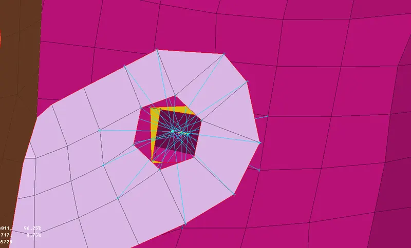
ANSA has automatically connecting between them by using RBE2 Elements like as shown in below image.
It had created the multiple number of a slave node & one master node for each part and connected between them by using two node RBE2 elements with constrainted all degree of freedoms.
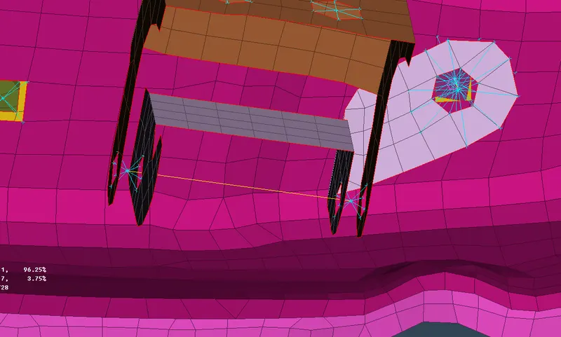
Similarly, we have to creating the connector between the hinge mating parts like as shown in below.
Make sure we have unconstrainted it on which along the Z axis rotation. Because, when we open the door, it will rotate about the Z axis.
III) Creating the RBE3 - CBUSH - RBE3 Elements :
A RBE 3 is stands for Rigid Body Element type 3, it has able to move in all possible directions Which is nothing but of there's no degree of freedom constraints on it and CBUSH have stiffness in all coordinates which in x, y & z.
Extract the curves from the FE model at where around the window glass edge by using "Feature 2 Curve " option under which mesh module & perimeter sub module.
Followingly, converting from curves to seam line by using convert gui option as looks like as shown below image.
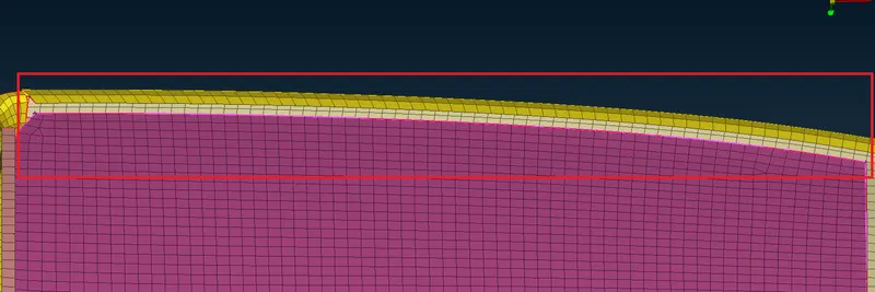
We have use those seam line to create the RBE3 - CBUSH - RBE3. Click the connector manager, immediately one tab has pop up which is "Connection Selection Assistant" and then followingly select the seam line which we going to perform and press middle mouse buttom to get open a new connection manager tab.
Select the parts properly, make sure provide space between them which is 10. Select the FE representation type which is RBE3-CBUSH-RBE3, followingly we have to provide the search distance, constraints the all degree of freedom and check the keep all branches which is help to realize it properly from one part node to another part node. Setting up like as shown in below image.
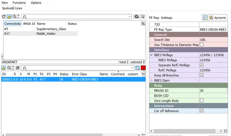
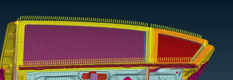
After realizing, it will create a connector between them by using RBE3 CBUSH RBE3 elements.
After done with RBE3 CBUSH RBE3 elements whereever it required, it will looks like as shown in the below image.
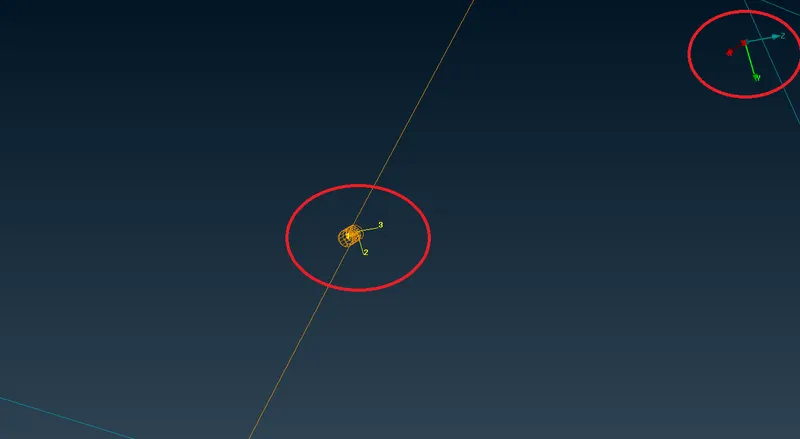
Make sure we have to keep the local coordinate is equal to the global coordinates. Now, both coordinates are have same vector direction.
IV) Creating the RBE3 - HEXA - RBE3 elements :
Create a COG point which is nothing but a center of gravity location for selected location. Followingly, converting into spot type point from COG point by using convert gui option.
After creating into the spot points, it will looks like as shown in the below image.

Click the connector manager, immediately one tab has pop up which is "Connection Selection Assistant" and then followingly select the spot type point which we going to perform and press middle mouse button to get open a new connection manager tab.
Selecting the parts which we are going to connect each other by using RBE 3 Elements with Hexa cube, in this case we have select the two parts.
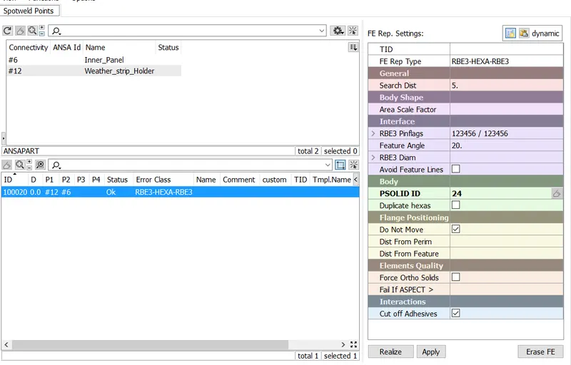
Select the FE representation type which is RBE3 HEXA RBE3, Provide the distance between the parts which is generally morethan the actually distance between them. Make sure keep the constraints to all possible degree of freedom. Applying it & click to realize.
Setting the connection card for spot weld like as shown in below.
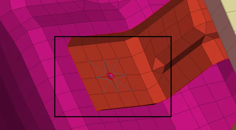
After click to realize, ANSA will automatically finds the master nodes from the selected two parts and find out the master nodes at center like as shown in below.
V) Creating the mass concentration node :
Whereever the handles, motor and other mechanism are presented in the system, we have to represent those parts with mass conecntration node while we modelling for simulations.
First of all, we have to create a RBE2 elements with multiple slave nodes & single node on both holes at where handle had fixed.
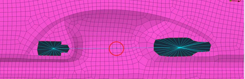
Next step, Previously created master node act as slave nodes and new master node has generating at middle like as shown in below image.
Inorder to assigning the mass concentration, we have select the "CONMi" element which means concentrated mass connection under which NASTRAN deck modules & Elements sub modules. Choose the CONM2 nodes under which CONMi
Select the center node, New tab window has pop up when we press the middle mouse button. Provide the mass value in tons units and ignored the remaning parameters like as shown in below tab image.
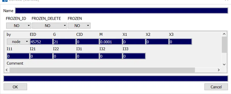
After entered the mass value in tons units, click Ok to which create apply mass concentration at center node.
CONCLUSION :
Successfully done to deploying the connector whereever required in the given Rear door component by using RBE2 Element, RBE3-CBUSH-RBE3 Element, RBE3-HEXA-RBE3 Element and CONMi element.
Outer :
Inner :
Learning Outcome :
I Learned from this challenge How to deploying the connector by using different 1D element.