Week 6:- Clamp Unit & Pin-Clamp Unit Design Challenge
DESIGN OF SWIVEL CLAMP UNIT
DESIGN OF SWIVEL CLAMP UNIT
Swivel Clamp Unit
Swivel Clamp unit is similar to that of a clamp unit. But, one change in the swivel clamp unit is that, the clamp arm is actuated by using the linear acting power cylinder. The Linear acting power cylinder clamps and de-clamps the clamp arm, by the linear motion of the connecting rod of power cylinder, which is connected to the clamp arm by bolt.
The Power cylinder automates the clamp arm movement by its linear action.
During the event of operation, the power cylinder swivels at the pivot point present on the blade, which performs the clamping and de-clamping action to the BIW panel. This swivel action names this clamp unit as ‘SWIVEL CLAMP UNIT’.
Ø Major parts of Swivel Clamp Unit
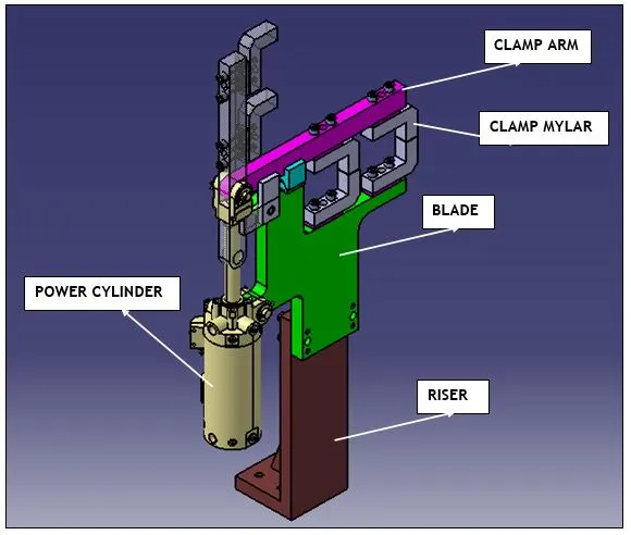
The major parts of Swivel Clamp Unit are as follows:-
1) NC block / mylars.
2) Clamp arm.
3) Power Cylinder.
4) Risers.
5) Blade.
6) Shims.
7) Travel Stopper.
DESIGN OF SWIVEL CLAMP UNIT
The designing of Swivel Clamp unit is similar to that of a clamp unit. But, one change in the swivel clamp unit is that, the clamp arm is actuated by using the linear acting power cylinder.
The Linear acting power cylinder clamps and de-clamps the clamp arm, by the linear motion of the connecting rod of power cylinder, which is connected to the clamp arm by bolt.
The Power cylinder automates the clamp arm movement by its linear action.
During the event of operation, the power cylinder swivels at the pivot point present on the blade, which performs the clamping and de-clamping action to the BIW panel. This swivel action names this clamp unit as ‘SWIVEL CLAMP UNIT’.
The Functional requirement of Swivel Clamp unit should satisfy the below condition : -
Ø Principle of Location
In order to study the complete location of a workpiece within a fixture, let us consider a workpiece in air as shown in below figure. The workpiece is assumed to have true and flat faces. In state of freedom, it may move in either of the two opposed directions along three mutually perpendicular axes – XX, YY and ZZ.
These six movements are called the “movements of translation”. Also, the workpiece rotate in either of two opposed directions around each axis, clockwise and anti-clockwise. These movements are called “rotational movements”.
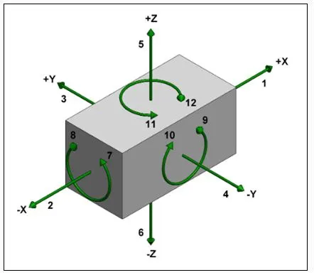
For any body there are total 12 Degrees of Freedom, as shown in above diagram,
Ø 6 Translational Degrees of Freedom
+X, -X, +Y, -Y, +Z, -Z
Ø 6 Rotational Degrees of Freedom
1.) Clockwise around X axis (CROT-X)
2.) Anticlockwise around X axis (ACROT-X)
3.) Clockwise around Y axis (CROT-Y)
4.) Anticlockwise around Y axis (ACROT-Y)
5.) Clockwise around Z axis (CROT-2)
6.) Anticlockwise around Z axis (ACROT-2)
We must fix all the 12 Degrees of Freedom in order to locate the workpieces in the fixture.
It is necessary to have 2 pins to locate car panel. one pin must arrest 4 way (4 translational motion) & other must arrest 2 way (2 rotational motion) of a car panel.
MAJOR PARTS OF A SWIVEL CLAMP UNIT
The Major parts to design a Swivel Clamp Unit are as follows: -
NC BLOCK / MYLARS
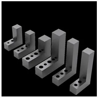
MYLAR is one kind of block that touches the panel and holds or clamps the panel.
Mylars are always designed in CAR LINE. Mylar is also called NC (Numerically Controlled) Block. Mylars are mounted on any block or plate with Shimming, so that height of mylar can be adjusted accordingly at the assembly level.
For ‘A’ class surfaces Nylon mylars are used. So that surface can be saved from scratches.
CLAMP ARM
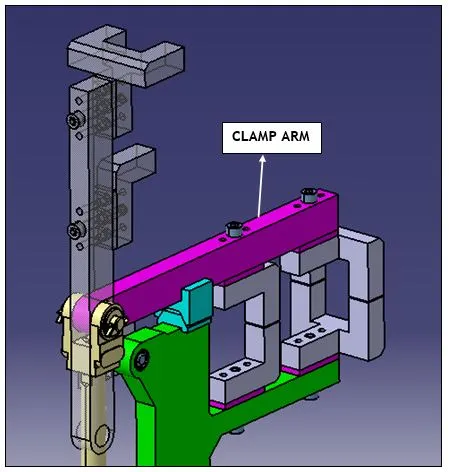
The Clamp arm is the arm which has the mylar blocks, used to clamp / de-clamp the BIW panel.
As the name comes as Clamp arm, the mylars which are connected to the clamp arm are called as clamp mylars.
The one end of the clamp arm has a hole made for connecting to the actuating rod of power cylinder.
The Clamp arm actuates by the help of power cylinder for clamping and de-clamping the BIW panel.
POWER CYLINDER
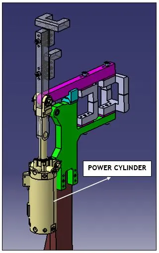
The power cylinder is a bought-out part / item, which is used to actuate the clamp arm.
The Power cylinder, has a piston inside the barrel, which connected to the one end of the rod, which is called as a piston rod, and the other end is connected to the clamp arm.
The piston linearly moves from one end of the cylinder barrel to the other end, by taking air as the input.
As, we are using the power cylinder for clamping and de-clamping the BIW panel, the type of duty used for power cylinder is ON / OFF duty.
The ON / OFF duty power cylinder performs clamping function, when we ON the power cylinder and de-clamps the BIW panel, when we select the OFF button.
RISER
The part which is mounted on the base plate and holds a clamp or pin cylinder on it, is called Riser.
Riser can be Standard Part or manufactured part, it varies from project to project.
A riser can be a Single part or welded part. Standard risers also have various shapes and sizes.
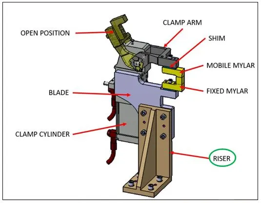
The Riser is shown in the above diagram by oval circle in green color.
BLADES
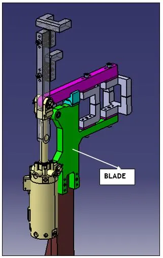
The plate which connects Riser to the Clamp cylinder is named as Blade.
This plate plays an important role in building the unit. The plate can be of any shape. But we need to keep in mind that the plate should be as compact as possible.
SHIMS
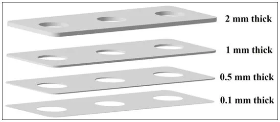
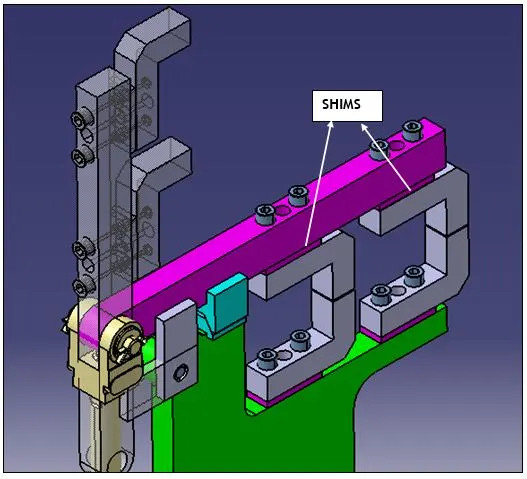
Shim is a set of thin plates (2 mm, 1mm, 0.5 mm, 0.25mm) that are used to adjust the gap or used for a better fit. Shimming can be of thickness 5mm, 8mm, or 10mm. in case no proper fitting between mylar and Panel due to manufacturing errors then this error can be removed using shims. Shims are placed in the carline position so that gap can be adjusted in the required direction like X, Y, or Z.
There are three types of shimming. These are one-way, two-way, and three-way shimming.
Number of shimming depends upon the NC cut angle and PIN angle with the car line.
v If NC cut is less than 15 deg. then mylar will have one-way shimming.
v If NC cut is more than 15 deg. in one direction then mylar will have a 2-way direction shimming
If NC has more than 15 deg. angle in two directions then mylar will have 3-way directional shimming.
TRAVEL STOPPER
The Travel Stopper is one of the important part of the Swivel clamp unit.
The Travel Stopper function is to stop the overtravel of the clamp arm, when the clamp arm performs the clamping action on the BIW panel.
The Travel Stopper is placed on the blade of the unit, in a such way that, the clamp arm performs the clamping action, within the set force limit to avoid the damage of the BIW panel, from further deformation by the mylars present in the clamp arm.
The Travel stopper is designed in a such way that, it can restrict 10 degrees of freedom.
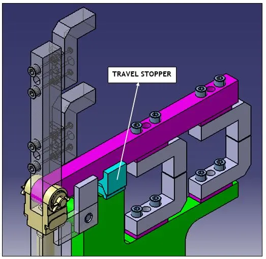
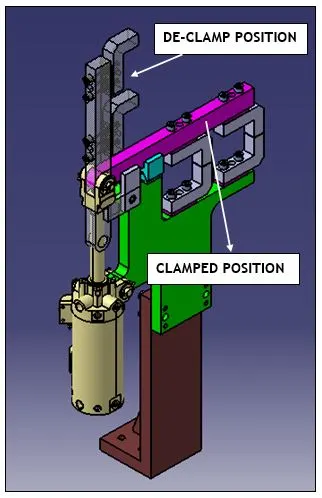
ASSEMBLED VIEW OF SWIVEL CLAMP UNIT-1
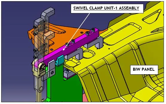
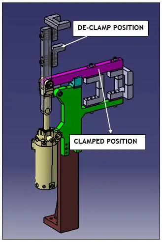
ASSEMBLED VIEW OF SWIVEL CLAMP UNIT-2
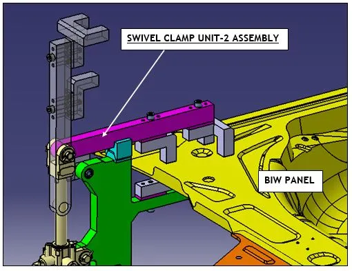
ASSEMBLED VIEW OF SWIVEL CLAMP UNIT-3 WITH ADDITIONAL ATTACHMENT OF FIXED UNIT
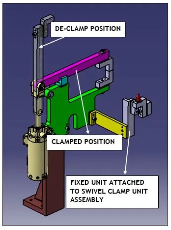
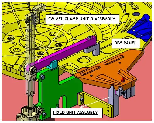
ASSEMBLED VIEW OF SWIVEL CLAMP UNIT-4
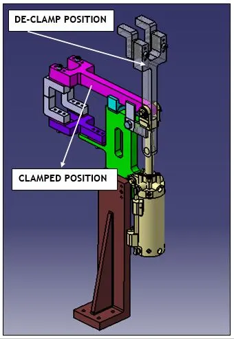
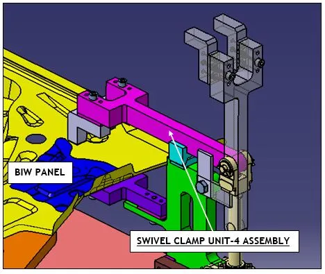
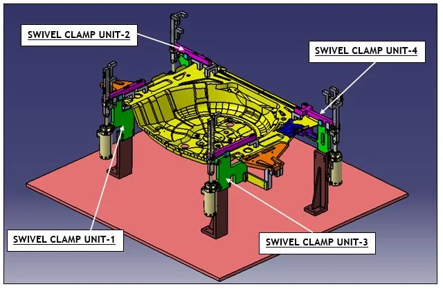
FINAL ASSEMBLED VIEW OF ALL THE SWIVEL CLAMP UNITS
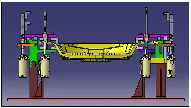
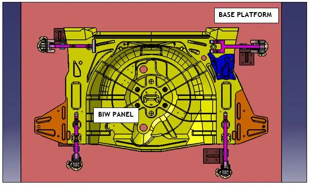
The Final assembled view shows all the swivel clamp unit assemblies, placed in a such way that, the BIW panel is held firmly from all the directions.
The Clamping forces to the BIW panel is held in a distributed manner, hence preventing the panel from deformations and loss of physical appearance.
The clamped position is shown in solid appearance, whereas the de-calmped position is shown with partial transparency, to understand the linear action of power cylinder, which actuates the clamp arm to perform the clamping engagement and clamping dis-engagement.