Week 6 - CHT Analysis on a Graphics card
AIM: To perform Conjugate Heat Transfer flow simulation over a graphics card using Ansys Fluent
OBJECTIVE:
- To conductsteady-state conjugate heat transfer analysis on a model of a Graphics Card
- To study the effect of different velocities on the temperature
METHODOLOGY:
Introduction:
Conjugate Heat Transfer:
When multiple modes of heat transfer ie., variations of temperature within solids and fluids, due to thermal interaction between the solids and fluids are involved then the process is called Conjugate Heat Transfer. In solids, conduction dominates whereas in fluids, convection dominates. It is used in processes which involve variations of temperature within solids and fluids due to thermal interaction between the solids and fluids. Heat Transfer is the study of thermal energy exchange between the two physical bodies, the rate of tansferred heat is directly proportional to the temperature difference between the bodies. It is used in following engineering applications like heat exchangers, HVAC, and electronic component design.
Wall functions are useful in calculation the solutions near the wall. Y+ is a dimensionaless quantity that can be used to understand whether the mesh is coarse or fine which in turn determines the need for wall functions. The Turbulent flow have a smaller laminar region near the wall and if we are to resolve the gradients at such a small region, very small grid size is required.
Procedure:
- Geometry preparation
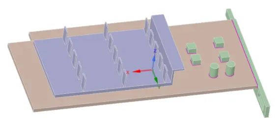
- IMPORT GEOMETRY IN SPACE CLAIM
-
Check for any edges in interference so that conformal mesh can be achieved
-
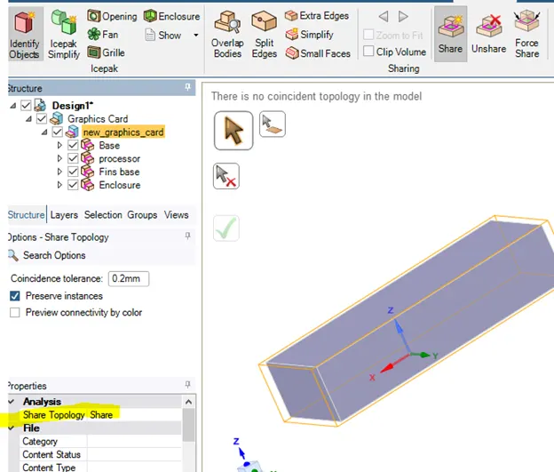
Enable Share topology between the different components so that necessary information can be shared between different zones of the mesh.
- Mesh
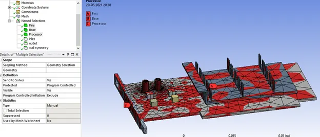
- OPEN MESH -->ENTITY SELECTION > FACE SELECTION/ Body Selection--> select the faces/Body of the geometry to be mentioned as boundaries NAMELY Fins, base, processor, INLET,OUTLET, wall and symmetry
- MESH -- > GENERATE MESH with available element size for baseline mesh
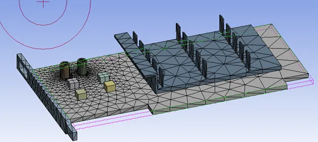
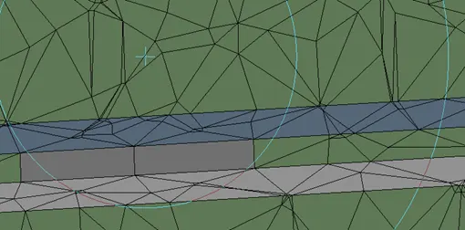
- Initailly keep the geometry in right direction to section . Now by using SECTION PLANE BUTTON, click and drag at the center to foam a line, so that it cuts the geometry.
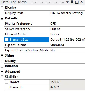
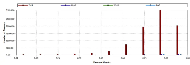
- QUALITY --> MESH METRIC --> ELEMENT QUALITY --> C GRAPH
- We have some quality of mesh less than 10%
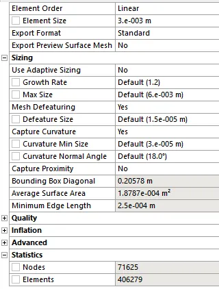
- Fine mesh
Element size: Curvature capture Fine mesh 0.003 m Body Sizing (Fin) 0.0005m Yes Body Sizing (Processor) 0.0005m Yes Body Sizing (Base) 0.003 m Yes 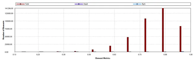
- QUALITY --> MESH METRIC --> ELEMENT QUALITY --> C GRAPH ( AS LONG AS ELEMENT QUANTITY is not lower than 5%, SIMULAION RUNS)
- Close the Mesh
- Set Up
- DOUBLE CLICK SETUP -- > FLUENT LAUNCHER -->DOUBLE PRECISION.
- Ansys Fluent is opened.
- In Graphics window --> GEOMETRY AND CONSOLE window is displayed.
- SETTING UP DOMAIN -->MESH --> select CHECK. Then in CONSOLE WINDOW --> it shows 'CHECKING MESH…. DONE'
- To Change the Units, SETTING UP DOMAIN --> click Units
- SETTING UP PHYSICS --> SOLVER --> select Time = STEADY, Type = PRESSURE BASED & Velocity Formation = ABSOLUTE.
- SETTING UP PHYSICS --> MODELS > select ENERGY. VISCOUS MODEL --> Model --> K-epsilon Model, REALIZABLE K-epsilon Model, STANDARD WALL FUNCTIONS -->OK.
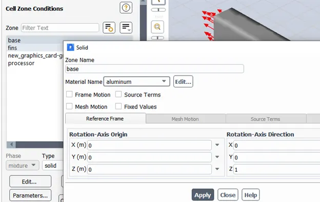
- Zones
| Zones | Material | Energy Source |
| Enclosure | Air | |
| Fin | Copper, Cu | |
| Base | Aluminium,Al | |
| Processor | Gold, Au |
yes value = 156250000 w/m^3 |
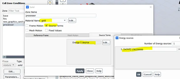
Heat Source calculation
| INPUT | VALUE | UNIT |
| Graphics Card Power | 10 | Watts |
| length and bredth of card | 8 | mm |
| Thickness of card (h) | 1 | mm |
| Volume of card (L*b*h) | 0.000000064 | m^3 |
| Heat Generated (Power/Volume of card)= | 156250000 | w/m^3 |
- Boundary Condition
|
Boundary Condition |
Values |
|
Inlet |
Type: Velocity Inlet Velocity: 1,3,5 m/s Temperature: 300 K |
|
Outlet |
Type: Pressure Outlet Pressure: 0 Pa (Gauge Pressure) Temperature: 300 K |
|
Symmetry |
Symmetry |
|
Wall |
Wall, Heat transfer =0 |
- Solution
- SOLVING --> CONTROLS, REPORTS, INITIALIZATION, RUN CALCULATION.
- INITIALIZATION --> select METHOD = HYBRID --> click t=0 INITIALIZE
- Reference Value calcuation
| Area | 0.022699 | m^2 |
| Velocity | 0.170003719 | m/s |
- RUN CALCULATION --> NO. OF ITERATIONS =500 and press CALCULATE.
5. Results and Discussion
CASE 1 Baseline
Residuals
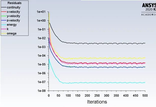
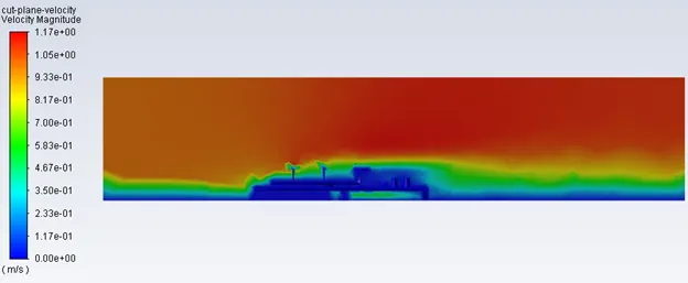
Inference: The solution can be considered as converged as variation of residuals are less and follows same pattern.
Velocity contour
Temperature Contour
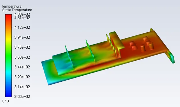
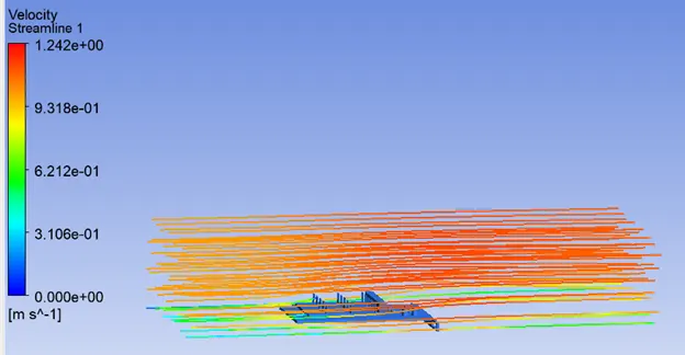
Inference: It is clear from the plot that for base line mesh the maximum velocity 438 K is observed processor when air flow is 1m/s.
Case2: Fine mesh Velocity = 1m/s
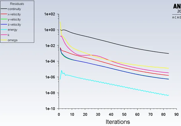
Residuals:
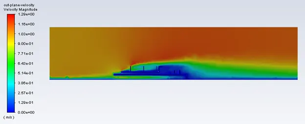
Velocity contour:
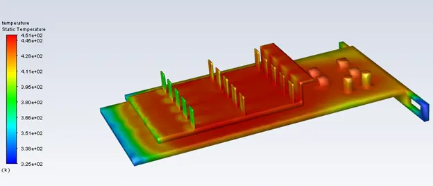
Temperature contour:
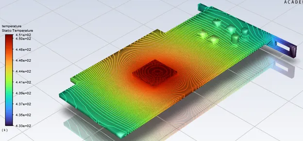
HOT SPOT
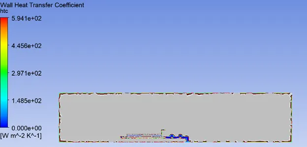
Heat Transfer Coefficeint:
Case3: Fine mesh Velocity = 3m/s
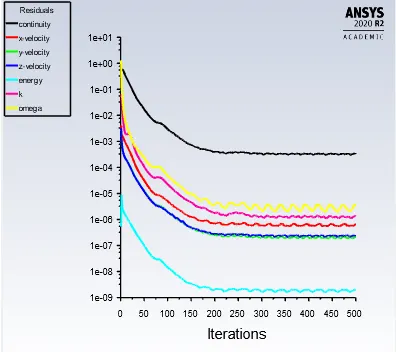
Residuals:
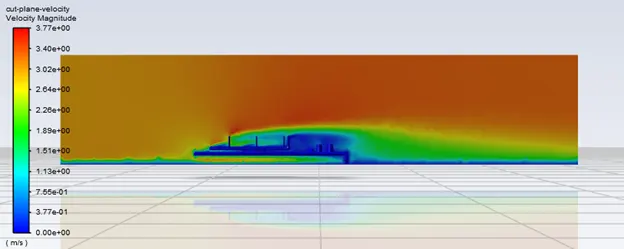
Velocity contour:
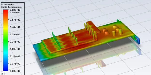
Temperature contour:
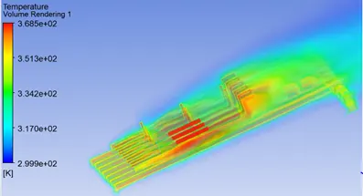
HOT SPOT
Heat Transfer Coefficeint:
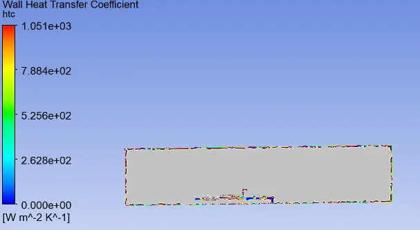
Case4: Fine mesh Velocity = 5m/s
Residuals:
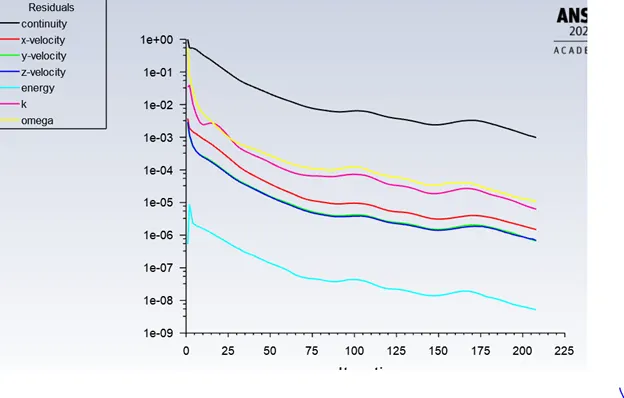
Velocity contour:
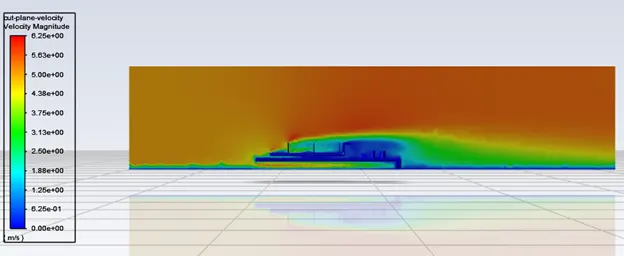
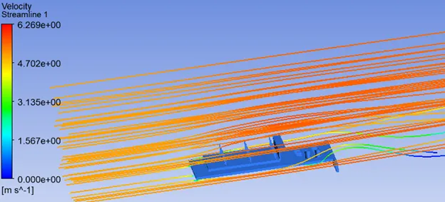
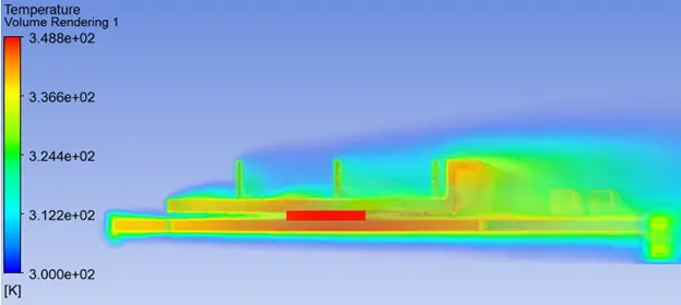
Temperature contour:
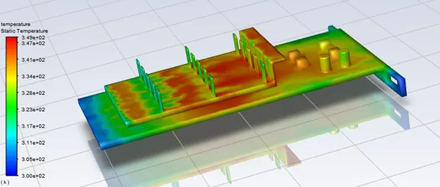
HOT SPOT
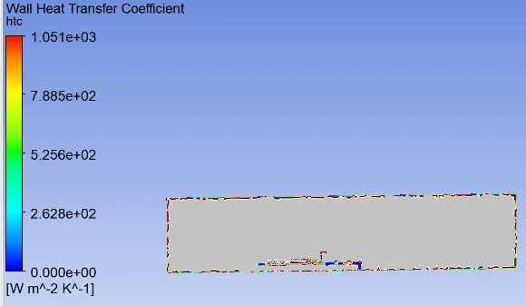
Heat Transfer Coefficeint:
Discussion:
| Fine Mesh | |||
| Velocity | 1m/s | 3m/s | 5m/s |
| Max Temp at Processor (K) | 451 (Max) | 368 | 349 |
| HTC at Fins (W/m^2K) | 5.94E+02 | 1.05E+03 | 1.05E+03 (Max) |
Inferences:
- Residuals: The solution can be considered as converged as variation of residuals are less/ the change in the gradients is very small and follows same pattern after 92 iterations for case 1, 165 iterations for case 2 and 215 iterations for case 3.
- Temperature Contour: High temperature is experienced by fin and base near the surface in contact with the processor. It is envisaged from the above plots that , hot spot region is formed in the processor(where energy source is given) which is in turn connected to base and fins. Heat transfer starts with Conduction at the contact region between the processor and fins and processor and base. After that heat transfer occurs by Convection through the inlet airflow. The maximum temperature observed in components is inversely proportional to the inlet fluid velocity. With the increase in the fluid velocity, the heat removal process by convection is quicker and less temperature is noted.
- Velocity Effect on Temperature: With increase in velocity Temperature dropped from 451 @ 1m/s to 368 @ 3m/s to 349@ 5m/s.
- Velocity Effect on HTC: With increase in velocity substantial rise in heat transfer coefficient was noticed. This in turn proves that that high-velocity cooling air can be an effective mode for heat dissipation
- Effect of Mesh Size : Fine mesh results in higher heat transfer coefficient compared to coarse mesh this is due to refinement of mesh done at fins and base of the fin and base of the graphic card for better computation of wall heat transfer coefficient at the fins and base. Finer the mesh more accurate the temperature distribution obtained.
Conclusion:
A steady-state CHT analysis on a graphics card model was performed by varying the inlet fluid velocities and mesh size. Following observations were made based on the contours:
- As mesh size reduces the temperature distribution is accurate and HTC increases
- The maximum temperature observed in components is inversely proportional to the inlet fluid velocity
- As velocity of airflow increases HTC increases