Week 6 - CHT Analysis on a Graphics card
AIM:
- To perform the steady state CHT simulation on a graphics card model
- To check the various difference occurs as we change the velocity of incoming air
INTRODUCTION:
In conjugated heat transfer analysis, there are multiple modes of heat transfer taking place simultaneously, like conduction and convection. There are many applications of such kind of simulation so it’s important to study such problems in detail.
CHT provides a detail analysis and predictions of temperature and hot spots so it cn help in designing the graphics card properly, if any sensitive component is placed in the hot spot region it can cause effect on the performance of the graphics card
PROBLEM STATEMENT:
- Simulate CHT analysis on a model of graphics card using proper material.
- Simulate by varying the velocity from 1m/s to 5m/s, 3 cases
- Find out the max temperature and heat transfer coefficient attained by the processor.
-
THEORY:
Conjugate Heat Transfer (CHT) Analysis:
Conjugate Heat Transfer analysis is used for the processes that involve a variety of temperatures concerning solids and fluids, due to thermal interaction between them. A typical example would be the heating or cooling of a solid by the flow of air.
The exchange of heat between two bodies is known as heat transfer and the rate of heat transfer is directly proportional to the temperature difference between them. Heat transfer in solids is usually occurred by conduction whereas in the case of fluids heat transfer occurs by convection. Efficiently combining heat transfers between solids and fluids is the key to design effective coolers, heaters, or heat exchangers. Forced convection is the most common way to achieve higher heat transfers. For some applications, the performance is further improved by combining convection with phase change (for example liquid water to vapor phase change).
Heat transfers in solid and heat transfers in fluids are usually combined in the majority of the applications. This is because fluid flows around solids or between solid walls and usually solids are immersed in the fluids.
An accurate description of parameters such as material properties, flow regimes, geometry configurations, selecting correct models based on the physics to be captured, heat transfer modes near the boundaries is needed for the analysis of temperature fields and heat transfer.
GEOMETRY:
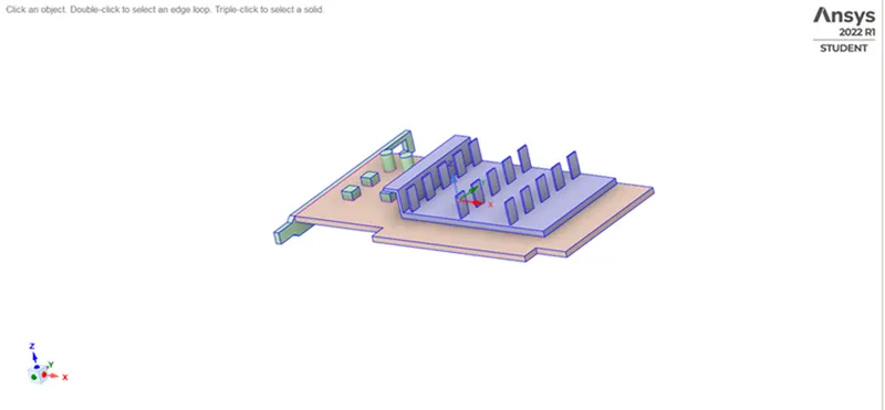
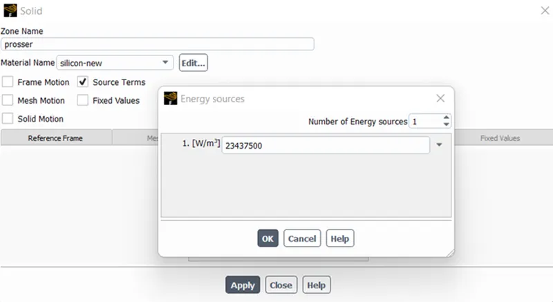
Processor is located below the fins and the heat is generated into the processor. All other parts are named under base.
Mesh:-
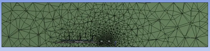
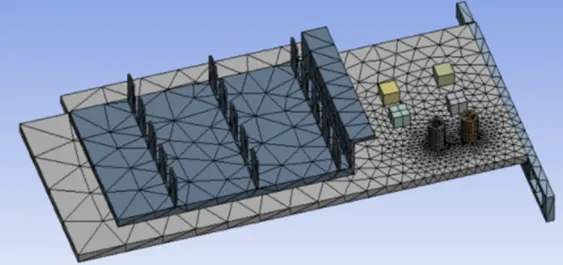
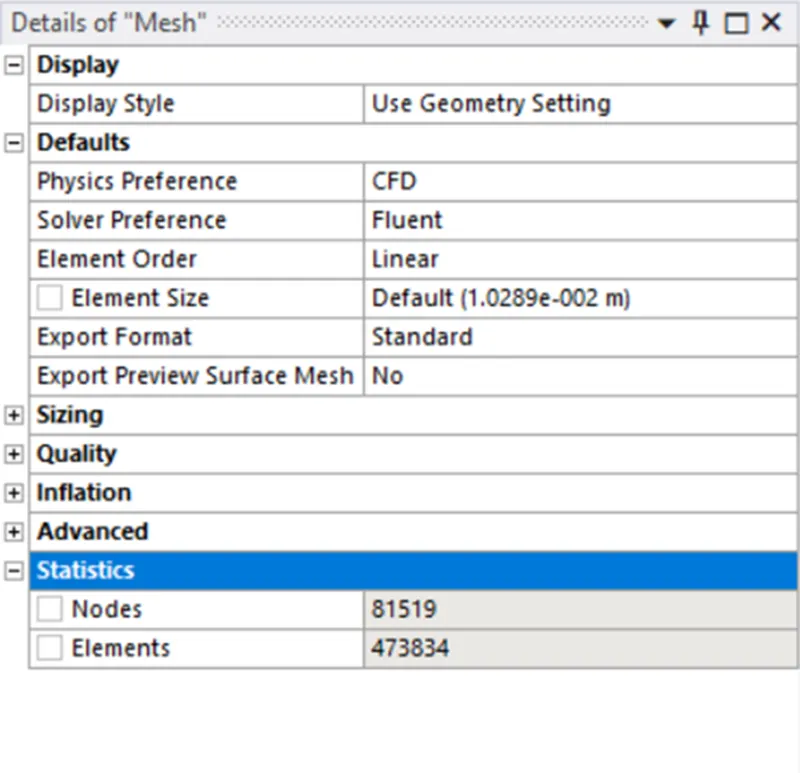
SETUP:
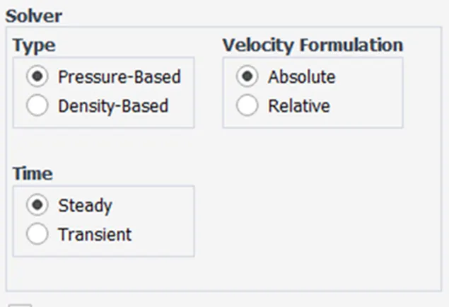
In this process we are using a steady state analysis were
Solver – pressure-based solver with energy equation activated as we have to study the temperature.
Results:-
BASE LINE MESH 5 m/s (inlet velocity)
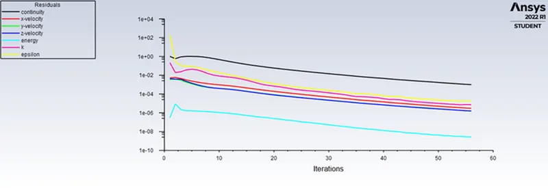
Residual:-
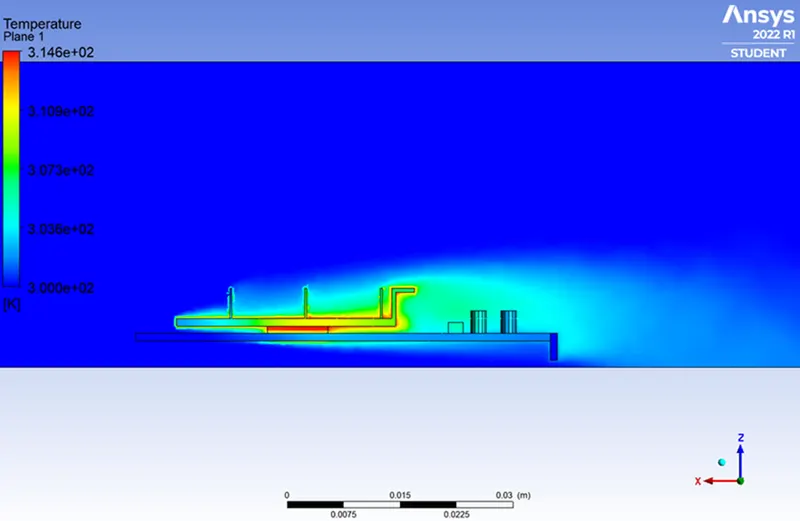
Temperature
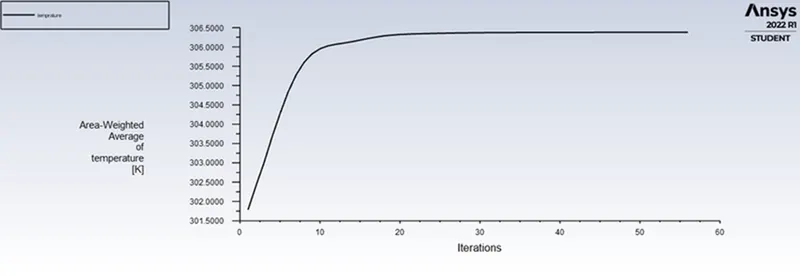
Average Temp. – 305K = 31.85 C
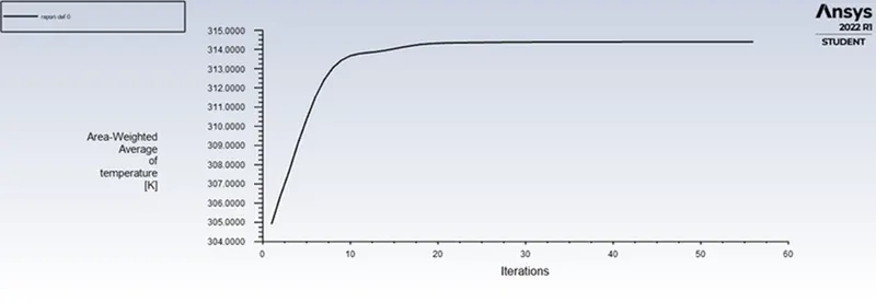
Max Temperature = 314.8 K = 41.65 C
Temperature distribution:-
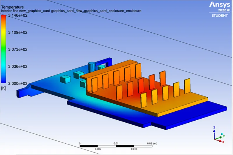
Local Temperature Distribution:-
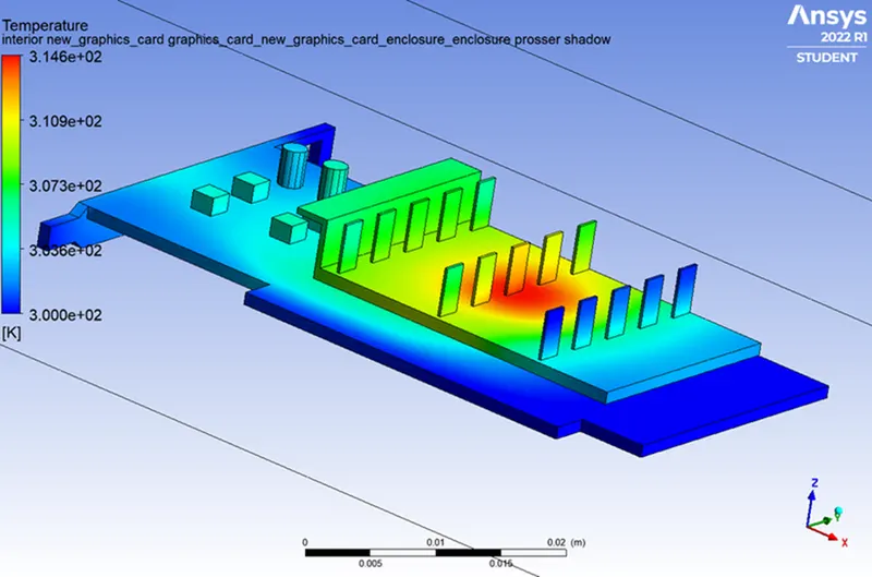
Temperature Rendering:-
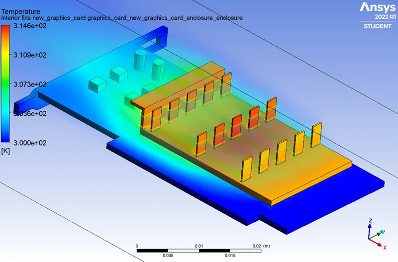
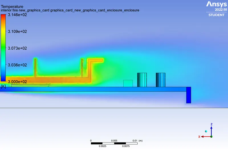
Temperature Distribution on plan:-
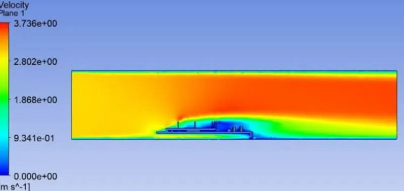
Velocity along plan:-
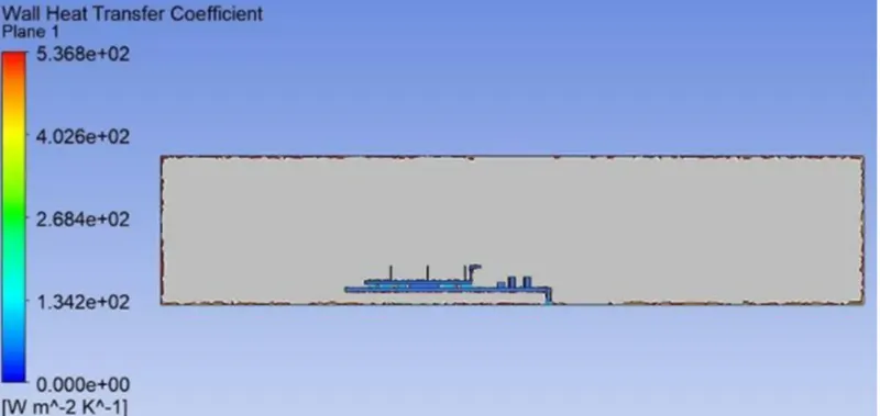
Wall heat Flux:-
Conclusion:- From this we can conclude that as inlet velocity get increased ....heat generated get decreased.