Week 6 - CHT Analysis on a Graphics card
CHT Analysis on a Graphic Card
Task: Perform a steady-state conjugate heat transfer analysis on a model of a graphics card. You can use appropriate materials of your choice for the simulation. Make sure to properly define the correct solid and fluid zones. Refer the video for further clarification and the model is provided below the video.
Run the simulation for best possible mesh with combination of coarse and refined mesh in different regions. Explain the reason for choosing the particular mesh settings.
Your Objectives:
Run the simulation by varying the velocity from 1m/sec to 5m/sec for at least 3 velocities and discuss the results.
Find out the maximum temperature and heat transfer coefficient attained by the processor.
Prove that the simulation has achieved convergence with appropriate images and plots.
Identify potential hotspots on the model.
Theory:
Conjugate Heat Transfer corresponds to the combination of heat transfer in solids and fluids (Conduction and Convection). It is mostly seen in processes like Heat Sink, Battery Cooling and Airflow over the solid object for cooling. When heat transfer takes place between solids and fluids, CHT analysis can be done to find the optimum result.
CHT Analysis is used in processes which involve variations of temp. within solids and fluids, due to thermal interaction between them.
CHT Analysis on Graphic Card:
- Import the given 3D model into Spaceclaim.
- Check Share Topology option in the left pane (Properties) as well as in “Workbench” tab à Share option.
- Open Mesh Module. Create Named Selections:
- Inlet
- Outlet
- Symmetry in the enclosure
- Processor
- Fins
- Base
- In Case 1, create a baseline mesh. (Element Size= 10.289mm)
- In Case 2 & 3, change element size to 3mm for enclosure. Add an inflation layer with total thickness of 5mm to the outer wall.
- Mesh size of processor = 0.2mm
- Mesh size of fins = 0.6mm
- Mesh size of base = 0.8mm
- Open Fluent next. Materials:
- Air (Fluid)
- Copper - Fins
- Silica – Processor (Density = 2328kg/m3, Spec. heat = 71-J/kgK, Thermal Conductivity = 150 W/mK)
- Steel - Base
- Boundary Conditions:
- Inlet Velocity:
- Case 1: 1m/s
- Case 2: 3m/s
- Case 3: 5m/s
- Inlet Temperature: 300K
- Processor Heat emission: Assume the processor consumes 83W of power. Dimensions = 8 x 8x 1m3. Therefore, energy produced = 1296875000 W/m3.
- Inlet Velocity:
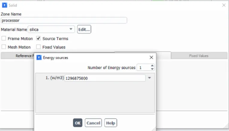
- Create Contours for Temperature and Wall heat transfer coefficient for processor, fins, and base from “Results” tab. Assign Animation accordingly from “Solve” tab.
- Solve the problem for 500 iterations.
Results:
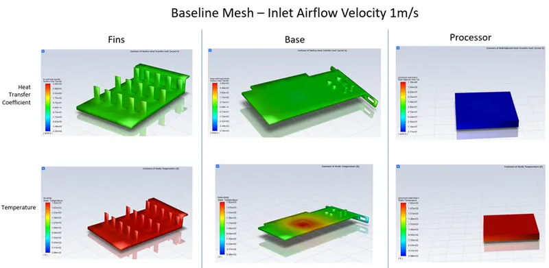
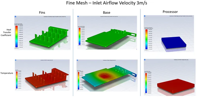
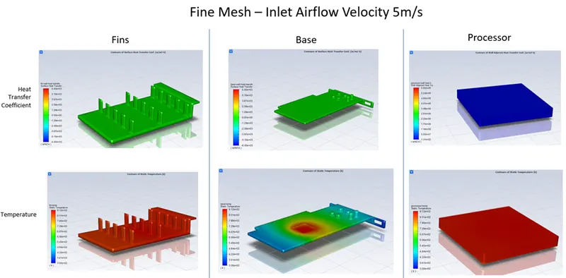
Conclusion:
|
Parameter |
Baseline mesh – 1m/s |
Fine Mesh – 3m/s |
Fine Mesh – 5m/s |
|
Max. Temp. Processor (K) |
1887 |
1150 |
900 |
|
Wall Heat Transfer Coefficient Processor (W/m2K) |
263 |
1340 |
1340 |
The processor, being the source of heat, is one of the hotspots. As the air velocity increases there was a drop in temperature and increase in heat transfer coefficient. This suggests that higher inlet velocity of air aids in heat dissipation in graphic card.
The refined mesh adds more clarity to the solution and gives realistic values.
The temperature contours suggest that the fins and base near the source of heat (processor) are hotspots.
Max temp. in the components is inversely proportional to inlet airflow velocity.