Week-6 Challenge: EV Drivetrain
AIM:
To learn about types of power converter circuits used in electric and hybrid electric vehicle, to solve a problem related to EV vehicle and to explain a blog about authors perspective.
THEORY:
The task of a power converter is to process and control the flow of electric energy by supplying voltages and currents in a form that is optimally suited for the user loads. Energy was initially converted in electromechanical converters (mostly rotating machines). Today, with the development and the mass production of power semiconductors, static power converters find applications in numerous domains and especially in particle accelerators. They are smaller and lighter and their static and dynamic performances are better. A static converter is a meshed network of electrical components that acts as a linking, adapting or transforming stage between two sources, generally between a generator and a load.
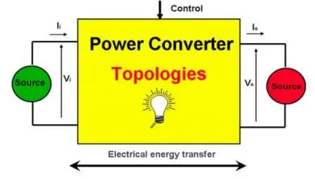
FIGURE.1
GOVERNING EQUATION:
To solve the problem, we have used following formula:
Speed -Torque Equation,
`omega=V/(K Phi)-R_a/(K Phi)^2*T_m`
Where,
`omega`= Speed of the motor
`V`= Supply Voltage
`Kphi`= constant= `E_b/omega`
`E_b`= Back E.M.F
`T_m`= Torque of moto`
`R_a`= Armature Resistance
OBJECTIVES:
- To find out which types of power converter circuits are employed in electric and hybrid electric vehicle.
- An Electric Vehicle's powertrain with 72V battery pack in shown in the diagram below. The duty ratio for acceleration operation is 'd1' and for the braking operation the duty ratio is 'd2'.
The other parameters of the electric vehicle are given below,
Motor and Controller Parameters:
Rated Armature voltage= 72 V
Rated armature current= 400 A
Ra= 0.5Ω, KΦ= 0.7 Volt second
Chopper Switching frequency= 400 Hz
The vehicle speed-torque characteristics are given by the below equation
To find what is EV steady state speed if duty cycle is 70%?
- To refer to the blog on below topic and explain in brief about author’s perspective.
SOLUTION:
TYPES OF POWER COVERTER CIRCUITS USED ARE:
i) Rectifiers:

FIGURE.2
A rectifier is an electrical device that converts alternating current (AC), which periodically reverses direction, to direct current (DC), which flows in only one direction. The reverse operation is performed by the inverter.
The process is known as rectification, since it "straightens" the direction of current. Physically, rectifiers take a number of forms, including vacuum tube diodes, wet chemical cells, mercury-arc valves, stacks of copper and selenium oxide plates, semiconductor diodes, silicon-controlled rectifiers and other silicon-based semiconductor switches. Historically, even synchronous electromechanical switches and motors have been used. Early radio receivers, called crystal radios, used a "cat's whisker" of fine wire pressing on a crystal of galena (lead sulphide) to serve as a point-contact rectifier or "crystal detector".
Rectifiers have many uses, but are often found serving as components of DC power supplies and high-voltage direct current power transmission systems. Rectification may serve in roles other than to generate direct current for use as a source of power. As noted, detectors of radio signals serve as rectifiers. In gas heating systems flame rectification is used to detect presence of a flame.
Depending on the type of alternating current supply and the arrangement of the rectifier circuit, the output voltage may require additional smoothing to produce a uniform steady voltage. Many applications of rectifiers, such as power supplies for radio, television and computer equipment, require a steady constant DC voltage (as would be produced by a battery). In these applications the output of the rectifier is smoothed by an electronic filter, which may be a capacitor, choke, or set of capacitors, chokes and resistors, possibly followed by a voltage regulator to produce a steady voltage.
ii) Inverters:
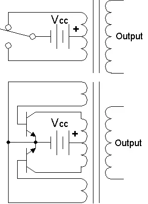
FIGURE.3
A power inverter, or inverter, is a power electronic device or circuitry that changes direct current (DC) to alternating current (AC). The resulting AC frequency obtained depends on the particular device employed. Inverters do the opposite of “converters” which were originally large electromechanical devices converting AC to DC.
The input voltage, output voltage and frequency, and overall power handling depend on the design of the specific device or circuitry. The inverter does not produce any power; the power is provided by the DC source.
A power inverter can be entirely electronic or may be a combination of mechanical effects (such as a rotary apparatus) and electronic circuitry. Static inverters do not use moving parts in the conversion process.
Power inverters are primarily used in electrical power applications where high currents and voltages are present; circuits that perform the same function for electronic signals, which usually have very low currents and voltages, are called oscillators. Circuits that perform the opposite function, converting AC to DC, are called rectifiers.
iii) Choppers:
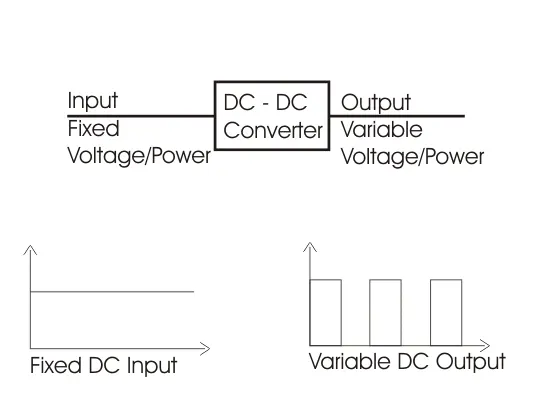
FIGURE.4
In electronics, a chopper circuit is used to refer to numerous types of electronic switching devices and circuits used in power control and signal applications. A chopper is a device that converts fixed DC input to a variable DC output voltage directly. Essentially, a chopper is an electronic switch that is used to interrupt one signal under the control of another.
In power electronics applications, since the switching element is either fully on or fully off, its losses are low and the circuit can provide high efficiency. However, the current supplied to the load is discontinuous and may require smoothing or a high switching frequency to avoid undesirable effects. In signal processing circuits, use of a chopper stabilizes a system against drift of electronic components; the original signal can be recovered after amplification or other processing by a synchronous demodulator that essentially un-does the "chopping" process.
iv) Regulator:
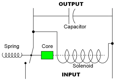
FIGURE.5
A voltage regulator is a system designed to automatically maintain a constant voltage level. A voltage regulator may use a simple feed-forward design or may include negative feedback. It may use an electromechanical mechanism, or electronic components. Depending on the design, it may be used to regulate one or more AC or DC voltages.
Electronic voltage regulators are found in devices such as computer power supplies where they stabilize the DC voltages used by the processor and other elements. In automobile alternators and central power station generator plants, voltage regulators control the output of the plant. In an electric power distribution system, voltage regulators may be installed at a substation or along distribution lines so that all customers receive steady voltage independent of how much power is drawn from the line.
TO FIND STEADY-STATE SPEED IF DUTY CYCLE IS 70% -
Given:
Rated Armature voltage= 72 V
Rated armature current= 400 A
Ra= 0.5Ω, KΦ= 0.7 Volt second
Chopper Switching frequency= 400 Hz
Speed-Torque equation of motor,
`omega=V/(K Phi)-R_a/(K Phi)^2*T_m`
For the value of 'V' we need multiply the Armature voltage with duty cycle,
therefore,
`V=72*(70/100)=50.4 text(Volts)`
By susbstituting the values in Speed -Torque equation of motor we get,
`T_m=70.56-0.98omega`
We have been given that Vehicle Speed Torque Characteristics as,
`T_v=24.7+0.0051w^2`
where,
`T_v`= Torque of the Vehicle
At Steady State,
`T_v=T_m`
By substituting the equations we get,
`24.7+0.0051omega^2=70.56-0.98omega`
On solving this Equation we get the vaules of `omega` as,
`omega=32.98,omega=-231.07`
We are considering positive value of `omega` as we have taken it has forward motion.
EXPLAINING THE BLOG:
Here the author first addresses that the technology always changes time. He states that technology which was 10 years ago has changed today by giving a battery example. Then he says how today brushless DC motors and Induction motors are used according the needs of an EV or HEV vehicles.
He then explains how a DC Brushless motor works and how an induction motor works. He then states that why inductions motors are used mostly in pure EVs and why DC brushless motors are used in HEVs. At the end he concludes that for the coming years induction and DC brushless motors might work together.
CONCLUSIONS:
- Thus we have achieved all the objectives sucessfully.
- Similar approach can be followed to solve diffirent type of problems.