Week-6 Challenge: EV Drivetrain
Q1. Which types of power converter circuits are employed in electric and hybrid electric vehicle?
Electric and hybrid electric vehicles (EVs and HEVs) have a variety of power converter circuits to manage and control the flow of electrical power within their systems. These circuits serve critical functions in converting and regulating voltage and current levels to meet the specific requirements of different vehicle components.
- DC-DC Converter :- One essential type of power converter is the DC-DC converter, which plays a key role in adjusting voltage levels within the vehicle's electrical system. It enables the conversion of high-voltage battery output to lower voltage levels suitable for charging auxiliary batteries or powering various low-voltage systems in the vehicle. By efficiently stepping up or stepping down the voltage, DC-DC converters ensure compatibility between different electrical components and optimize energy usage.
- DC-AC Converter :- Another crucial component is the DC-AC inverter, primarily used in electric vehicles. It converts the high-voltage DC power supplied by the battery into high-frequency AC power. This AC power is then directed to the electric motor(s) responsible for propelling the vehicle. Through precise control of frequency, voltage, and waveform characteristics, the inverter regulates the speed and torque of the motor, translating driver inputs into desired propulsion.
- AC-DC rectifiers :- In the case of hybrid electric vehicles, AC-DC rectifiers come into play. These converters convert the AC power generated by the internal combustion engine or captured through regenerative braking into DC power. The rectified DC power is then utilized for charging the traction battery or supplying electricity to the vehicle's electrical systems. By efficiently transforming and channeling the power generated by the engine or recovered from braking, AC-DC rectifiers contribute to maximizing energy utilization and optimizing the vehicle's overall efficiency.
- Bidirectional DC-DC converters :- These converters are integral to hybrid electric vehicles, enabling the flow of power in both directions between the high-voltage battery and the 12V auxiliary battery. These converters allow for effective energy transfer between the two batteries, stepping up or stepping down voltage levels as needed. This bidirectional capability ensures optimal utilization of energy resources, facilitating battery charging, power delivery to auxiliary systems, and smooth operation of the vehicle.
- On-board chargers play a critical role in electric vehicles, converting AC power from external sources, such as the grid or charging stations, into the DC power required for charging the traction battery. These chargers typically incorporate rectification and DC-DC conversion stages, along with power factor correction techniques to ensure efficient and reliable charging processes. By transforming and regulating external AC power into a suitable DC form, on-board chargers enable the replenishment of the vehicle's energy storage system.
- Motor controllers are vital power converter circuits responsible for managing the power delivered to the electric motor(s) in both EVs and HEVs. These controllers regulate the speed and torque of the motor, responding to driver inputs and system requirements. By precisely modulating the power electronics components, such as insulated gate bipolar transistors (IGBTs) or silicon carbide (SiC) MOSFETs, motor controllers ensure optimal motor performance and efficient energy utilization, contributing to the overall performance and efficiency of the vehicle.
In summary, power converter circuits are essential components within the electrical systems of electric and hybrid electric vehicles. By converting, regulating, and managing electrical power, these circuits facilitate the efficient operation, power distribution, and energy utilization of the vehicle, ultimately enhancing performance, range, and sustainability.
Q2.
Given parameters:-
Va = Rated Armature voltage= 72 V
Ia = Rated armature current= 400 A
Ra = Armature Resistance = 0.5Ω
KΦ= 0.7 Volt second
Chopper Switching frequency= 400 Hz
Vehicle Speed-torque characteristics = Tu = 24.7 + (0.0051)w² ........(Eq 1)
Duty cycle = 70% = 0.7
To find = EV steady state speed(w)
Solution :-
w=(V/KΦ)-((T*R)/(KΦ)^2) .......Eq 2 for Steady State speed
Here,
V= Va*dutycycle = 72*0.7 = 50.1
Therefore,
w = (72*0.7/0.7) - ((T*0.5)/(0.7)^2)
w = 72 - 0.5T/0.49
T = 70.56 - 0.98w .......(Eq 3)
Substituting Eq 3 in Eq 1,
70.56 - 0.98w = 24.7 + (0.0051)w²
0.0051w^2 + 0.98w - 45.86 = 0
By solving further, we get
w = - 231.07184 & 38.91498
Since speed is positive w = 38.91498
Hence, Steady state speed for EV if duty cycle is 70% is 38.91498 rad/s
Q3. Develop a mathematical model of a DC Motor for the below equation using Simulink.
ω= (V/Kϕ">ϕ) -(Ra/Kϕ">ϕ^2).T
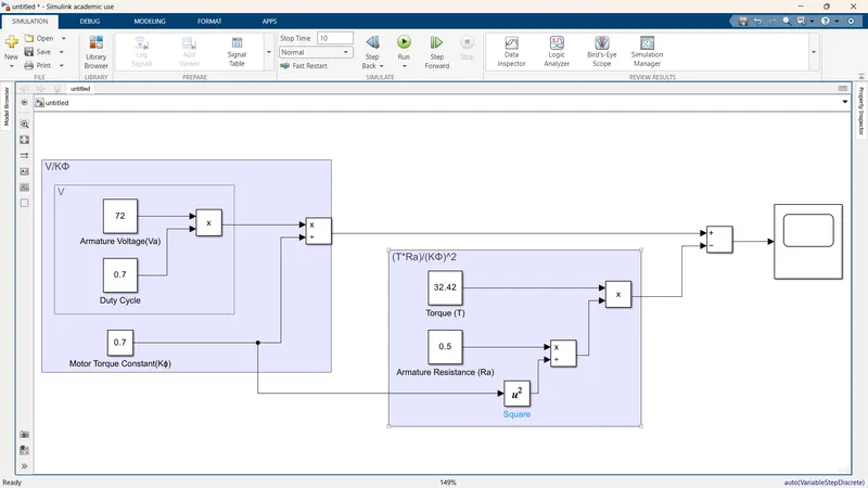
- Above mathematical modeling is based on the equation ω= (V/Kϕ) -(Ra/Kϕ^2)*T
- Values are imputed from the previous problem
- Link for the model is uploaded below
- Here, we have taken constant blocks for armature voltage (Va), duty cycle ,armature resistance (Ra), Torque (T)
- By using the product block for multiplication of Va and duty cycle, we get V, later by using the divide block for V and KΦ we get V/KΦ.
- For ((T*R)/(KΦ)^2), divide block is used for Ra and (KΦ)^2 later product block between T and R/(KΦ)^2.
- A Substract block is used for subtraction between V/KΦ and ((T*R)/(KΦ)^2) giving us (V/KΦ)-((T*R)/(KΦ)^2)
Q4. Refer to the blog on below topic:
Induction Versus DC brushless motors by Wally Rippel, Tesla
Explain in brief about author’s perspective.
Rippel begins by highlighting the diversity in the world of internal combustion engines, where various configurations exist to cater to different requirements such as price and performance. He questions why a single best engine type has not emerged, despite the expectation that it would have been determined by now. Similarly, he asserts that the same principle applies to electric vehicle drives.
He reminisces about the past when lead acid batteries, DC brush motors, and contactor controllers were prevalent. However, these components have been replaced by lithium batteries and either DC brushless or induction motors, with contactors giving way to modulating inverters. Rippel ponders whether these current elements will also become obsolete in the near future or if a certain level of stability may be achieved. While acknowledging the difficulty of predicting the future, he predicts that both induction and brushless machines will continue to compete for many years to come. Each technology will have its advocates and detractors, leading to ongoing debates and discussions in the field.
For DC brushless drives, Rippel describes that the rotor contains permanent magnets, generating a DC magnetic field. This magnetic field interacts with currents in the stator windings, producing a torque between the rotor and stator. To ensure optimal efficiency, the magnitude and polarity of the stator currents must be continuously varied in response to the rotor's rotation. This control is achieved through an inverter, which is responsible for current modulation.
Moving on to induction motor drives, Rippel mentions Nikola Tesla's invention of the 3-phase induction motor as a forerunner. He notes that the stator configuration for both induction and DC brushless motors is similar, with three sets of distributed windings in the stator core. The crucial distinction lies in the rotor design.
In contrast to the DC brushless rotor, the induction rotor does not have magnets. Instead, it consists of stacked steel laminations with buried conductors, forming a shorted structure. When currents flow in the stator windings, a rotating magnetic field is created, which induces a voltage across the shorted structure. The magnitude of this voltage depends on the speed difference between the rotor and the electrical frequency. As a result, currents are generated within the rotor conductors, which contribute to the desired rotor torque when interacting with the magnetic field.
Later he explains that 3-phase induction motors can start under load without an inverter when connected to utility power. They are directly compatible with conventional AC power, which has been a key factor in their success. In contrast, a brushless DC motor lacks starting torque when directly connected to fixed-frequency utility power. It requires an inverter that maintains phase alignment with the rotor's angular position.
While 3-phase induction motors are versatile, Rippel acknowledges their limitations. They cannot operate from DC power and are constant-speed machines when used with utility power. Additionally, their starting torque and running peak torque capabilities are somewhat limited compared to DC motors.
However, by incorporating an inverter (without feedback control), induction machines can be powered by a battery or DC source, enabling variable speed by adjusting the inverter frequency. Though torque performance is lower compared to DC machines, the addition of feedback loops allows the inverter to produce the exact frequency desired by the motor. This enhancement enables induction motors to compete with DC and DC brushless motors in vehicle applications.
Rippel provides a comprehensive comparison between DC brushless drives and induction drives, shedding light on their respective strengths and considerations. While DC brushless drives exhibit advantages such as lower rotor heat generation, higher peak point efficiency, and the ability to operate at unity power factor, induction drives offer adjustability, cost advantages, and the potential for better average efficiency.
DC brushless drives rely on permanent magnets in the rotor, providing a fixed magnetic field that interacts with currents in the stator windings. This interaction produces torque between the rotor and stator. In contrast, induction drives feature rotors without magnets, employing currents in the stator windings to generate a rotating magnetic field. This field induces voltage across the rotor, resulting in currents that interact with the magnetic field to produce desired torque.
The absence of magnets in induction drives contributes to their cost advantage over DC brushless drives, as permanent magnets can be expensive. Furthermore, induction drives possess the advantage of adjustability, as their magnetic fields are proportional to the voltage-to-frequency ratio (V/f). This enables the inverter to reduce voltage at light loads, minimizing losses and maximizing efficiency. In contrast, DC brushless drives lack the ability to adjust the strength of their fixed magnetic fields.
Additionally, Wally Rippel mentions that induction drives exhibit field weakening capabilities, allowing for lower inverter ratings and costs, especially for high-performance drives. Moreover, spinning induction machines produce little to no voltage when de-excited, making them easier to protect. On the other hand, controlling induction drives is more complex and involves intricate control laws compared to DC brushless drives, resulting in higher development costs.
In terms of their applications, Rippel observes that DC brushless drives have become dominant in hybrid vehicles, while induction drives have found notable use in high-performance pure electric vehicles such as the General Motors EV-1, AC Propulsion vehicles, and the Tesla Roadster.
Hence, it is concluded that DC brushless drives will likely remain dominant in the hybrid and plug-in hybrid markets, while induction drives are expected to maintain their stronghold in high-performance pure electric vehicles. However, he raises the question of what will happen as hybrids become more electrically intensive and performance levels increase.
Ultimately, the future of these drives in the rapidly evolving landscape of hybrid and electric vehicles remains uncertain. However, Wally Rippel's analysis suggests that both induction and DC brushless drives will play significant roles, each catering to specific market segments and evolving requirements.
A google docs link for the above is pasted below:-
https://docs.google.com/document/d/1Wcd1F8vA4Z7qCfyJrRr7_7-iQmKVAIMgRiVn9Ot-uX0/edit?usp=sharing