Week-6 Challenge: EV Drivetrain
- Which types of power converter circuits are employed in an electric and hybrid electric vehicle?
There are four main categories of power converter circuits that are used in electric and hybrid electric vehicles. They are listed and elaborated below:-
- AC to DC Converter:-
AC to DC converters is electrical circuits that transform alternating current (AC) input into direct current (DC) output. They are used in power electronic applications where the power input is a 50Hz or 60Hz sine wave AC voltage that requires power conversion for DC output. AC to DC converters use rectifiers to turn AC input into DC output, regulators to adjust the voltage level, and reservoir capacitor to smooth the pulsating DC. This video explains how AC is converted into DC. Youtube link is given below:-
https://www.youtube.com/watch?v=VZctTmmS-gA
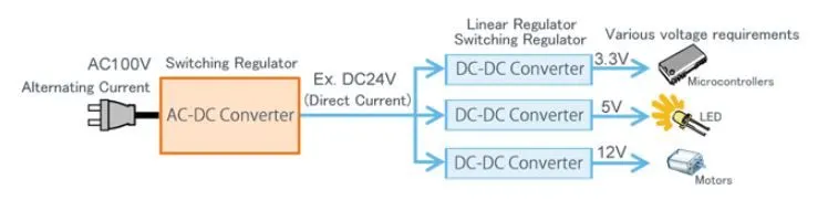
Linear devices are simple and relatively inexpensive, but also large and inefficient. They process excess power as heat, which can be problematic for the same temperature-sensitive applications.
Switching devices are more complex AC to Dc converters that use a switched-mode power supply (SMPS). A switching regulator shifts very quickly between full-on and full-off states, minimizing wasted energy. Switching converters are more efficient, smaller, and lighter, but also more complicated. They can cause electrical noise problems if not carefully suppressed, and simple designs may also have a poor power factor.
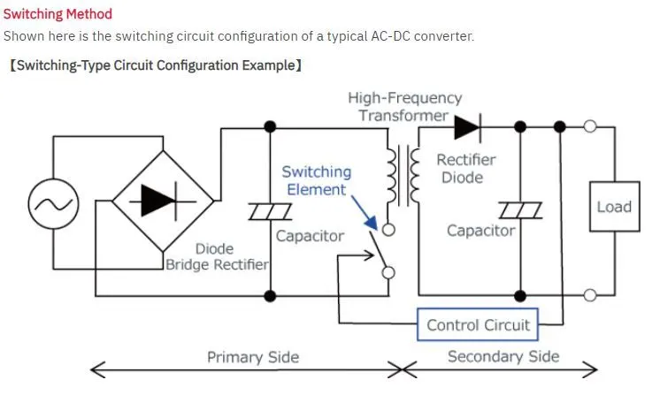
In the case of EVs or HEVs, the battery pack which operates with a DC power supply is charged at home or at a charging station both of which are supplied power in AC form from the electric grid. So, the chargers for these vehicles are an example of the AC to DC power converter.
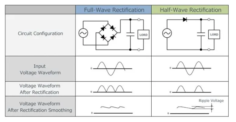
The EV charger comes in this category. It has a rectifier that takes AC supply and gives DC output. Rectifier circuits may be single-phase or multiple-phase. Most low-power rectifiers for domestic equipment are single-phase, but three-phase rectification is very important for industrial applications. Single-phase has 2 types half-wave rectification and full-wave rectifier.
- DC to DC Converter:-
A DC to DC converter is an electronic circuit or electromechanical device that converts a source of direct current (DC) from one voltage level to another. It is a type of electric power converter. Power levels range from very low (small batteries) to very high ( High-voltage power transmission).
DC to DC converter is used in portable electronic devices such as cellular phones and laptop computers, which are supplied with power from batteries primarily. Such electronic devices often contain several sub-circuits, each with its own voltage level requirement different from that supplied by the battery or an external supply (sometimes higher or lower than the supply voltage). Additionally, the battery voltage declines as its stored energy are drained. Switched DC to DC converters offer a method to increase the voltage from a partially lowered battery voltage thereby saving space instead of using multiple batteries to accomplish the same thing.
Most DC to DC converter circuits also regulates the output voltage. Some exceptions include high efficiency LED power sources, which are kind of DC to DC converter that regulates the current through the LEDs, and simple charge pumps which double or triple the output voltage.
DC to DC converters is available as integrated circuits (ICs) requiring few additional components. Converters are also available as complete hybrid circuits modules, ready for use within an electronic assembly.
Linear regulators which are used to output a stable DC independent of input voltage and output load from higher but less stable input by dissipating excess volt-amperes as heat could be described literally as DC to DC converters, but this is not usual usage. (The same could be said of a simple voltage dropper resistor, whether or not stabilized by the following voltage regulator or Zener diode.)
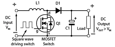
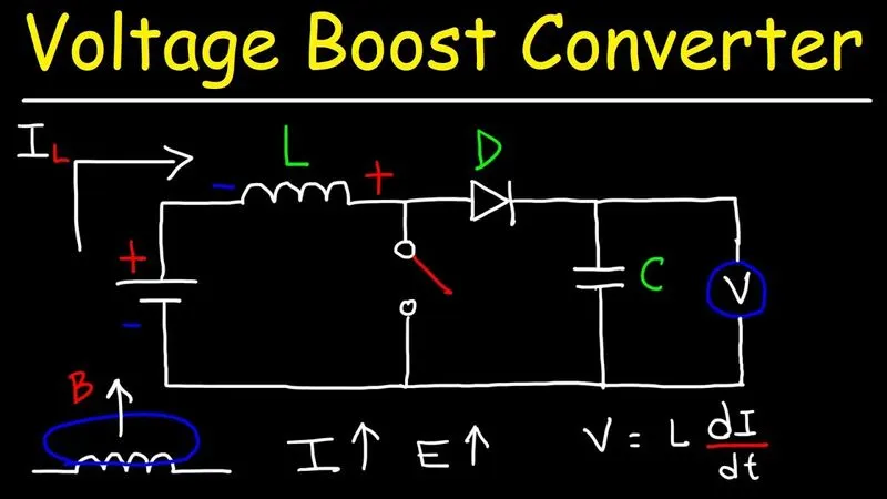
There are 2 main types of DC to DC converters which are isolated and non-isolated types. The non-isolated type can be subdivided into 5 types:-
- Buck - to step down the voltage.
- Boost - to step up the voltage.
- Buck/Boost - this can do both steps up and step down operations but is mainly used to reverse polarity.
- Cuk - similar to the Buck/Boost type.
- Charge Pump - to step up/step down the voltage for low power sources.
The isolated type can be subdivided into 2 types:-
- Flyback Converter - similar to the Buck-Boost converter except it uses a transformer instead of an inductor to store energy.
- Forward Converter - this type will use a transformer to send energy between the input and output in a single step.
- DC to AC Converter:-
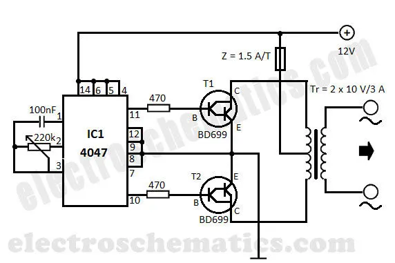
This type of converter takes a DC supply and converts it to an AC one. The power that is supplied from a battery or capacitor can have its form changed to the AC type for use in homes or systems which have an AC load. For instance, the power generated by solar panels is stored in batteries in the DC form and this can power a house that uses an AC power supply so that we can utilize this power from the mains. This type of converter is referred to as an 'inverter' and is widely used in homes and in EV/HEVs.
In the case of EVs and HEVs, the battery pack will supply its power to the inverter. The inverter contains a transformer that consists of a primary and secondary winding. The current from the battery is first supplied to the primary winding where the electronic switches will repeatedly reverse the direction of the current to create an AC waveform. This current will return back the way it came from. The AC current in the primary winding will induce an AC current in the secondary winding which then supplies this current to an AC load e.g. the AC traction motor.
DC to AC Converter 12V to 220V Voltage converter circuit given below:-
- AC to AC Converter:-
A solid-state AC to AC converter converts an AC waveform to another AC waveform, where the output voltage and frequency can be set arbitrarily. The output voltage and/or frequency can be changed or maintained depending on the application. This converter has many applications in our daily life e.g. lamp dimming, motor speed control.
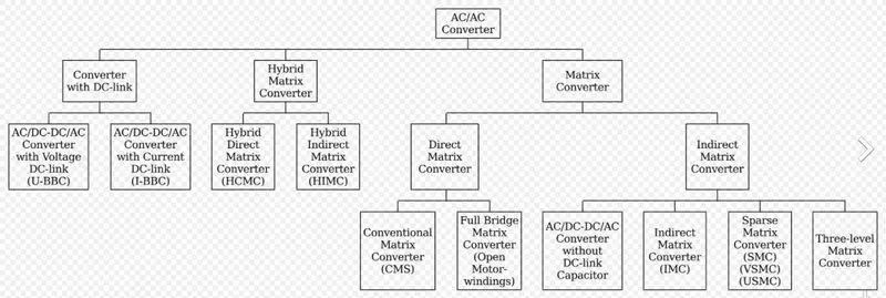
AC to AC converters can be categorized as follows:-
- Indirect AC-AC (or AC/DC-AC) converters (i.e., with rectifier, DC link, and inverter), such as those used in variable frequency drives
- Cycloconverters
- Hybrid matrix converters
- Matrix converters (MC)
- AC voltage controllers
2. An Electric Vehicle's powertrain with a 72V battery pack is shown in the diagram below. The duty ratio for acceleration operation is 'd1' and for the braking operation the duty ratio is 'd2'.
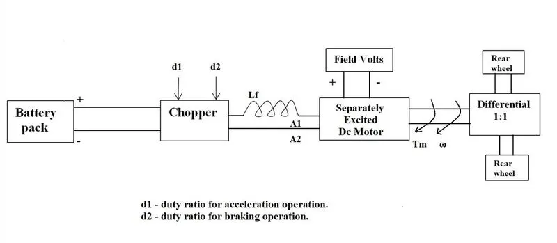
The other parameters of the electric vehicle are given below,
Motor and Controller Parameters:
Rated Armature voltage= 72 V
Rated armature current= 400 A
Ra= 0.5Ω, KΦ= 0.7 Volt second
Chopper Switching frequency= 400 Hz
The vehicle speed-torque characteristics are given by the below equation:
What is EV steady state speed if duty cycle is 70%?
Solution =
The motor voltage can be calculated as
Where,
is battery voltage, and
d is the duty cycle.
Vm=72V⋅0.7=50.4V��=72�⋅0.7=50.4�
Armature Resistance is equal to:
Ra=VaIa��=����
Ra=72V400A=0.18ohms��=72�400�=0.18�ℎ��
The torque-speed relationship is established by this equation:
T=V⋅KϕRa−(Kϕ)2⋅ωRa�=�⋅����-(��)2⋅���
Where,
V� is the battery or supply voltage,
Kϕ�� is the motor constant,
Ra�� is the armature resistance,
ω� is the angular speed of the motor in rad/s,
T� is the motor torque
On substituting all the given data we find one equation for torque:
T=50.4⋅0.70.5−(0.7)2.ω0.5=70.56−0.98ω�=50.4⋅0.70.5-(0.7)2.�0.5=70.56-0.98�---------Eq(1),
From the data given by the another equation for the torque is
Tv=24.7+(0.0051)w2��=24.7+(0.0051)�2---------Eq(2),
Bycombining equations 1 and 2, we end up with the single equation:
70.56−0.98ω=24.7+0.0051(ω)270.56-0.98�=24.7+0.0051(�)2
0.0051(ω)2+0.98ω−45.86=00.0051(�)2+0.98�-45.86=0----------Eq(3),
The final equation represents a quadratic equation a(x)2+bx+c=0�(�)2+��+�=0, where, the root x� is given by
−b±√(b)2−4⋅a⋅c2⋅a-�±(�)2-4⋅�⋅�2⋅�
x� represents the angular speed ω� and by substituting the constants we get the values for ω� as 38.92 rad/s and -230.07 rad/s.
Here EV steady-state speed, if the duty cycle is 70% then the -ve value of speed shows that the torque is transferred to the motor externally where the +ve value states that the motor generated torque reaches the wheels.
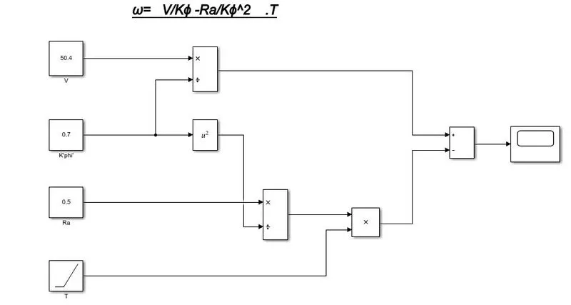
3. Develop a mathematical model of a DC Motor for the below equation using Simulink.
ω= V/Kϕ -Ra/Kϕ^2 .T
ANSWER:-
- Simulink modal for given equation given below:-
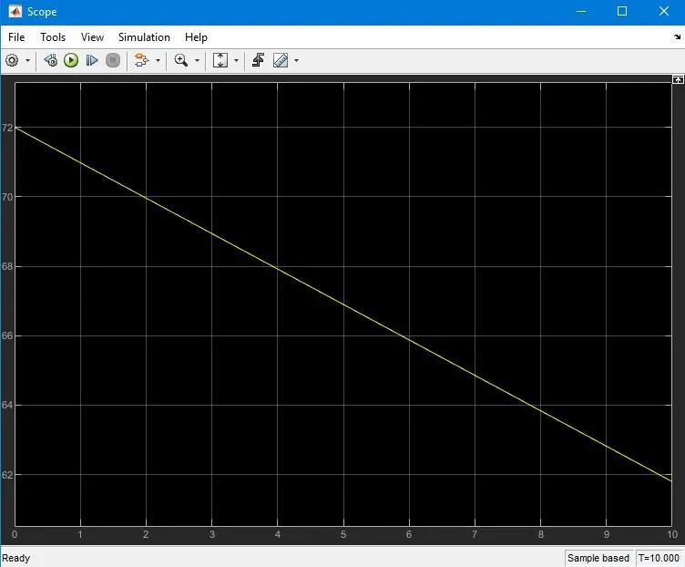
- RESULTS:-
4). Refer to the blog on the below topic:
Induction Versus DC brushless motors by Wally Rippel, Tesla
- Explain in brief the author’s perspective.
The author writes this blog to entail the differences between the two most commonly used motor drives in the automobile industry. The DC brushless motor drive and the induction motor drive. Rippel goes into detail about the differences in construction, working, and cost between the two drive types. However, with what he has written, he has not arrived at the conclusion that one type is better than the other. In the last lines of the opening paragraph, Rippel writes that "there is no one best engine type" and that it is all a matter of personal preference when it comes to choosing an engine. It is in this same regard that he ends the blog stating that there is still 'no winner' when it comes to motor drive selection either. In spite of both motor drive types having similarities, they also have their benefits and drawbacks.
For DC brushless drives, we are told that their construction implements 2 or more permanent magnets at the rotor to generate a DC magnetic field. It also consists of a stator core (made up of thin, stacked laminations). It also uses an inverter for the current control, meaning that it cannot run on a DC power supply as the current direction has to be changed repeatedly to maintaining constant torque.
For Induction drives, their rotor has no magnets but instead stacked steel laminations with buried peripheral conductors which form a 'shorted structure'. It is the current in the stator windings that generates a rotating magnetic field that interacts with the rotor.
Induction motors can be used directly with power from the mains and do not require an inverter to start the drive and generate the starting torque. It has the ability to start under the mains load applied. However, DC brushless drives cannot do the same. They cannot generate a starting torque when connected to a mains power supply. They require an inverter to do this.
Induction motor drives cannot run on a DC power supply and are solely dependent on AC power supply. Also, when they are connected to a 3 phase mains supply, the rotor rotates at a constant speed and also they have a limited starting torque as well as peak torque. In order to rectify this an inverter can be used to operate the induction drive from a DC power supply or a battery. Also, if the inverter frequency is varied, then the constant speed is no longer an issue - it can be varied.
- Difference between DC Brushless Motor and Induction Motor given below:-
| S.NO. | DC BRUSHLESS MOTOR | INDUCTION MOTOR |
| 1 | DC Supply | AC Supply |
| 2 | Require position sensor | Require speed sensor |
| 3 | The torque generated due to interaction of rotor and stator magnetic field | Stators rotating magnetic field induces a current in rotor laminations, which interact with the stator magnetic field and produce torque |
| 4 | The rotor includes two or more permanent magnets to generate a magnetic field | The rotor includes stacked steel laminations with shorted peripheral conductors for induced magnetic field |
| 5 | Less Rotor heat generated, easier rotor cooling, and higher peak point efficiency. Power factor up to 100% can be reached | Rotor cooling is difficult. Maximum power factor that can be achieved in 85% |
| 6 | Permanent magnets are costly and ferromagnets cannot be brought near the motor | Difficult to control, complex control laws for inverters |
| 7 | As for size increases, losses increase, and part-load efficiency decreases | As for size increases, losses remain approximately the same |
| 8 | The magnetic field strength cannot be adjusted thus only single torque output can be obtained | The magnetic field strength can be varied as a function of voltage supply and frequency for optimized torque output. |
| 9 | Preferred for HEV | Preferred for pure EV for high performance |
CONCLUSION:-
- Types of Converters used in HEV's and EV's vehicles
- To find the velocity using the Torque-Speed expression.
- To create the Simulink modal of given equations.
- To get to know about the induction and DC motor and try to find the best options available.
REFERENCES:-