Week-6 Challenge: EV Drivetrain
Power Electronics:
Power electronics is the application of solid state converters to the control and conversion of electric power.
The first high power electronic devices were mercury arc valves. In modern systems, the conversion is performed with semiconductor switching devices such as diodes, thyristors, and power transisitors such as the power MOSFET and IGBT. In contrast to electronic systems concerned with transmission and processing of signals and data, in power electronics substantial amounts of electrical energy are processed. An AC/DC converter (rectifier) is the most typical power electronics device found in many consumer electronic devices, e.g. television sets, personal computers, battery chargers, etc. The power range is typically from tens of watts to several hundred watts. In industry a common application is the variable speed drives that is used to control an induction motor. The power range of VSDs start from a few hundred watts and end at tens of megawatts.
The power conversion systems can be classified according to the type of the input and output power
- AC to DC (rectifier)
- DC to AC (inverter)
- DC to DC
- AC to AC
AC to DC converter (rectifier):
A rectifier is an electrical device that converts alternating current (AC), which periodically reverses direction, to direct current (DC), which flows in only one direction.
The process is known as rectification since it "straightens" the direction of the current. Physically, rectifiers take several forms, including vacuum tube diodes, wet chemical cells, mercury-arc valves, stacks of copper and selenium oxide plates, semiconductor diodes, silicon-controlled rectifiers, and other silicon-based semiconductor switches. Historically, even synchronous electromechanical switches and motors have been used. Early radio receivers, called crystal radios, used a "cat's whisker" of fine wire pressing on a crystal of galena (lead sulfide) to serve as a point-contact rectifier or "crystal detector".
Rectifiers have many uses but are often found serving as components of DC power supplies and high-voltage direct-current power transmission systems. Rectification may serve in roles other than to generate direct current for use as a source of power. As noted, detectors of radio signals serve as rectifiers. In gas heating systems flame rectification is used to detect the presence of a flame.
Depending on the type of alternating current supply and the arrangement of the rectifier circuit, the output voltage may require additional smoothing to produce a uniform steady voltage. Many applications of rectifiers, such as power supplies for radio, television, and computer equipment, require a steady constant DC voltage (as would be produced by a battery). In these applications the output of the rectifier is smoothed by an electronic filter, which may be a capacitor, choke, or set of capacitors, chokes, and resistors, possibly followed by a voltage regulator to produce a steady voltage.
More complex circuitry that performs the opposite function, that is converting DC to AC, is called an inverter.
Half way rectification Full wave rectification
DC to AC converter(inverter): A power inverter, or inverter, is a power electronic device or circuitry that changes direct current (DC) to alternating current (AC).The input voltage, output voltage and frequency, and overall power handling depend on the design of the specific device or circuitry. The inverter does not produce any power; the power is provided by the DC source.A power inverter can be entirely electronic or maybe a combination of mechanical effects (such as a rotary apparatus) and electronic circuitry. Static inverters do not use moving parts in the conversion process.Power inverters are primarily used in electrical power applications where high currents and voltages are present; circuits that perform the same function for electronic signals, which usually have very low currents and voltages, are called oscillators.
DC to DC converter(Chopper):
DC to DC converter is very much needed nowadays as many industrial applications are dependent upon DC voltage source. The performance of these applications will be improved if we use a variable DC supply. It will help to improve the controllability of the equipment also. Examples of such applications are subway cars, trolleybuses, battery-operated vehicles, etc. We can control and vary a constant DC voltage with the help of a chopper.
Chopper is a static power electronics device that converts fixed DC voltage/power to variable DC voltage or power. It is nothing but a high-speed switch that connects and disconnects the load from the source at a high rate to get variable or chopped voltage at the output.
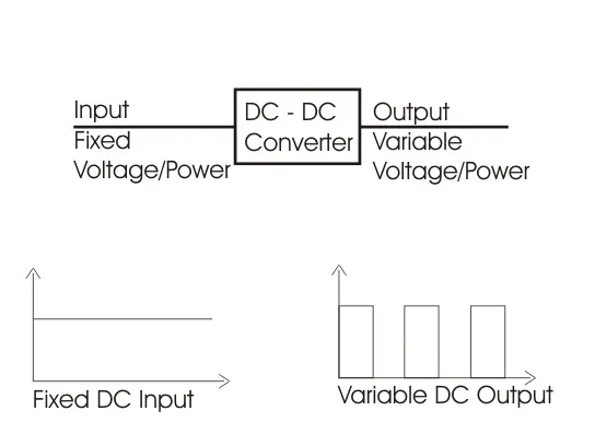
These devices are represented as a switch in a dotted box for simplicity. When it is closed current can flow in the direction of the arrow only.
1) Step down Chopper :
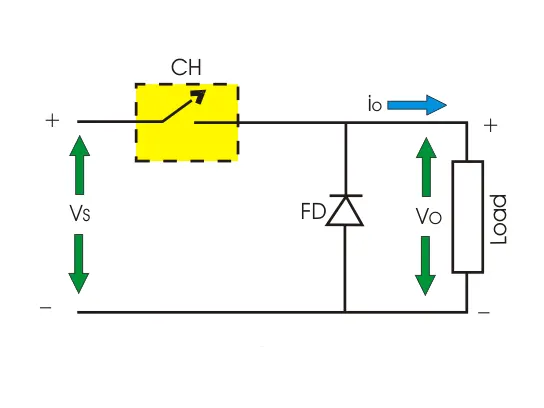
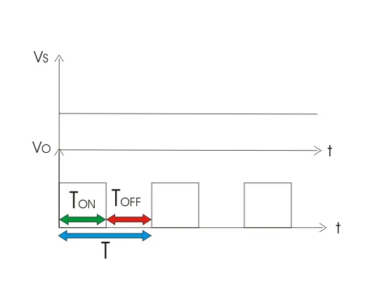
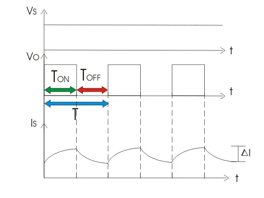
Step down chopper as Buck converted is used to reduce the i/p voltage level at the output side. Circuit diagram of a step down chopper is shown in the adjacent figure.
2) Step up Chopper or Boost Converter :
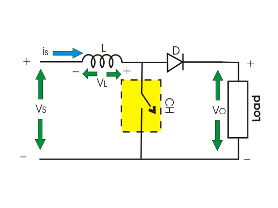
Step up chopper or boost converter is used to increase the input voltage level of its output side. Its circuit diagram and waveforms are shown below in figure.
AC to AC converter:
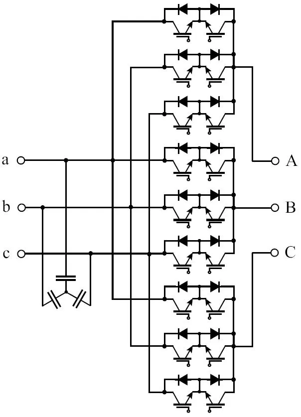
A solid-state AC-to-AC converter converts an AC waveform to another AC waveform, where the output voltage and frequency can be set arbitrarily.
2)
ans
Given data:
Rated Armature voltage = 72V
Rated armature current = 400A.
RaRa = 0.5ΩΩ
KΦKΦ = 0.7 Volt second.
Chopper switching frequency = 400 Hz
Solution:
Rolling Resistace,Frr=μrr⋅m⋅gFrr=μrr⋅m⋅g.
Drag Force,Fad=12⋅ρ⋅A⋅v2⋅CdFad=12⋅ρ⋅A⋅v2⋅Cd
Tractive Effort,Fte=Frr+FadFte=Frr+Fad
Let,
μrr=0.009μrr=0.009
Cd=0.2Cd=0.2
m=1000kgm=1000kg
ρ=1.1614kg/m3ρ=1.1614kg/m3
A=2m2A=2m2
r=0.28mr=0.28m
Frr=0.009∗1000∗9.81Frr=0.009∗1000∗9.81 = 88.29 N
Fad=12∗1.1614∗2∗v2∗0.2Fad=12∗1.1614∗2∗v2∗0.2.
Fad=0.01821∗ω2Fad=0.01821∗ω2
Fte=88.29+0.01821∗ω2Fte=88.29+0.01821∗ω2
Also ,we know that
Fte=G.TrFte=G.Tr,where G = 1
T0.28=88.29+0.01821∗ω2T0.28=88.29+0.01821∗ω2
Tv=24.7+0.0051ω2Tv=24.7+0.0051ω2
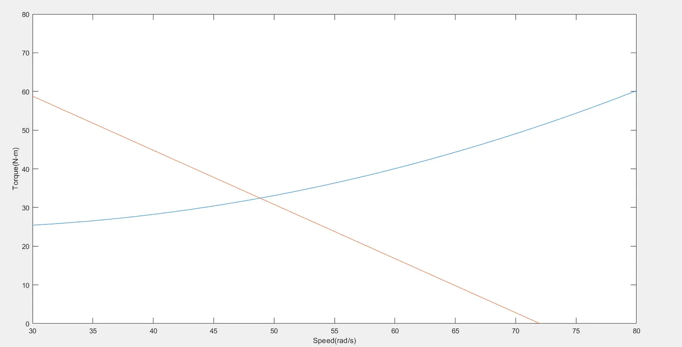
This is the torque speed characterstics of the vehicle.
Now the angular velocity ωω of DC motor i given by
ω=VkΦ−T⋅RkΦ2ω=VkΦ-T⋅RkΦ2
So, T=V⋅kΦR−ω⋅kΦ2RT=V⋅kΦR-ω⋅kΦ2R
Now putting all the values the above equation
Since duty cycle is 70%,V = 72*0.7 = 50.4V
T=50.4∗0.70.5−ω∗0.720.5T=50.4∗0.70.5-ω∗0.720.5
Tm=70.56−0.98ωTm=70.56-0.98ω
At steady state,
Tv=TmTv=Tm
On equating both the sides we get,
ω=38.90rad/sω=38.90rad/s
EV staedy state speed if duty cycle is 70% is 38.90 rad/s.
MATLAB program for speed torque characterstics.
clear all
close all
clc

% given data
V = 72; % rated armature voltage
I = 400; % rated armature current
R = 0.5; % armature resistance
K_phi = 0.7; % constant factor
f = 400; % chopper switching frequency

omega = linspace(0,100,50);
% Speed-Torque characterstics equation
T_v = 24.7 + 0.0051*omega.^2;
V = 72*0.7;
T_m = 70.56 - 0.98*omega;
omega = (V/K_phi)-((R*T_m)/K_phi);


% plotting the result
plot(omega,T_v)
hold on
plot(omega,T_m)
axis([30 80 0 80])
xlabel('Speed(rad/s)')
ylabel('Torque(N-m)')
Result:
3)
ans:-
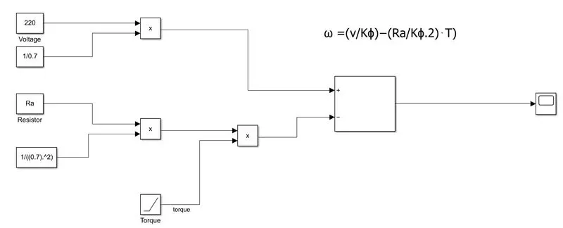
ω=(vKϕ)−(RaKϕ.2)⋅Tω=(vKϕ)-(RaKϕ.2)⋅T
model for the above equation :
Result :-
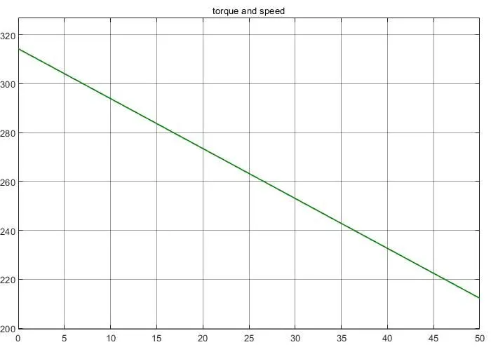
This result show torque speed curve for DC motor
4)
ans
Induction Versus DC brushless motors by Wally Rippel, Tesla
A brushless DC electric motor (BLDC motor or BL motor), also known as an electronically commutated motor (ECM or EC motor) and synchronous DC motors, are synchronous motors powered by direct current (DC) electricity via an inverter or switching power supply which produces electricity in the form of alternating current (AC) to drive each phase of the motor via a closed-loop controller. The controller provides pulses of current to the motor windings that control the speed and torque of the motor. This control system replaces the commutator (brushes) used in many conventional electric motors.
The construction of a brushless motor system is typically similar to a permanent magnet synchronous motor (PMSM), but can also be a switched reluctance motor, or an induction (asynchronous) motor. They may also use neodymium magnets and be outrunners (the stator is surrounded by the rotor), in runners (the rotor is surrounded by the stator), or axial (the rotor and stator are flat and parallel).
The advantages of a brushless motor over brushed motors are high power-to-weight ratio, high speed, electronic control, and low maintenance. Brushless motors find applications in such places as computer peripherals (disk drives, printers), hand-held power tools, and vehicles ranging from model aircraft to automobiles. In modern washing machines, brushless DC motors have allowed replacement of rubber belts and gearboxes with a much simpler and more reliable direct-drive design.
An induction motor or asynchronous motor is an AC electric motor in which the electric current in the rotor needed to produce torque is obtained by electromagnetic induction from the magnetic field of the stator winding. An induction motor can therefore be made without electrical connections to the rotor. An induction motor's rotor can be either wound type or squirrel-cage type.
Three-phase squirrel-cage induction motors are widely used as industrial drives because they are self-starting, reliable, and economical. Single-phase induction motors are used extensively for smaller loads, such as household appliances like fans. Although traditionally used in fixed-speed service, induction motors are increasingly being used with variable-frequency drives (VFD) in variable-speed service. VFDs offer especially important energy savings opportunities for existing and prospective induction motors in variable-torque centrifugal fan, pump, and compressor load applications. Squirrel cage induction motors are very widely used in both fixed-speed and variable-frequency drive applications.
Conclusion:
It has been concluded that DC brushless drives will likely continue to dominate in the hybrid and coming plug-in hybrid markets, and that induction drives will likely maintain dominance for the high-performance pure electrics. The question is what will happen as hybrids become more electrically intensive and as their performance levels increase? The fact that so much of the hardware is common for both drives could mean that we will see induction and DC brushless live and work side by side during the coming golden era of hybrid and electric vehicles.