Week-6 Challenge: EV Drivetrain
AIM :-
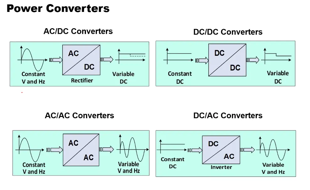
- To types of power converter circuits are employed in electric and hybrid electric vehicle.
An Electric Vehicle is a vehicle that uses a combination of different energy sources, Fuel Cells (FCs), Batteries and Supercapacitors (SCs) to power an electric drive system. In EV the main energy source is assisted by one or more energy storage devices. Thereby the system cost, mass, and volume can be decreased, and a significant better performance can be obtained. Two often used energy storage devices are batteries and SCS. They can be connected to the fuel cell stack in many ways. A simple configuration is to directly connect two devices in parallel, (FC/battery, FC/SC, or battery/SC). However, in this way the power drawn from each device cannot be controlled, but is passively determined by the impedance of the devices. The impedance depends on many parameters. temperature, state-of-charge, health, and point of operation. Each device might therefore be operated at an inappropriate condition. health and efficiency.
The voltage characteristics also have to match perfectly of the two devices, and only a fraction of the range of operation of the devices can be utilized. in a fuel cell battery configuration the fuel cell must provide almost the same power all the time due to the fixed voltage of the battery, and in a battery/supercapacitor configuration only a fraction of the energy exchange capability of the supercapacitor can be used. This is again due to the nearly constant voltage of the battery. By introducing DC/DC converters one can chose the voltage variation of the devices and the power of each device can be controlled.
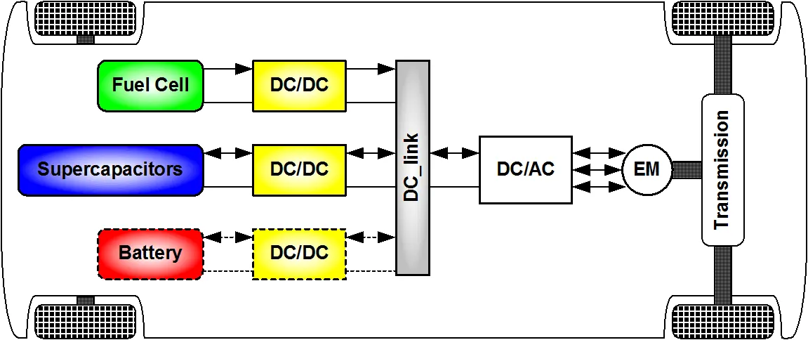
DC/DC converters can be designed to transfer power in only one direction, from the input to the output. However, almost all DC/DC converter topologies can be made bi-directional. A bi-directional converter can move power in either direction, which is useful in applications requiring regenerative braking.
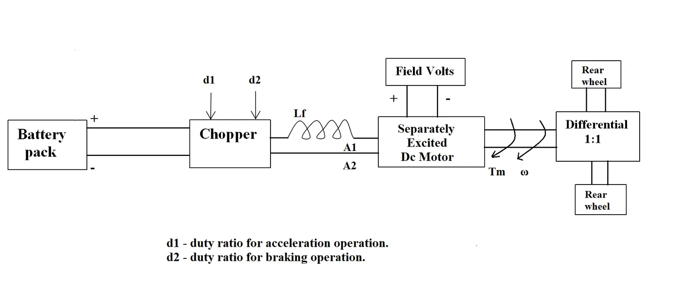
2. An Electric Vehicle's powertrain with 72V battery pack in shown in the diagram below. The duty ratio for acceleration operation is 'd1' and for the braking operation the duty ratio is 'd2'.
The other parameters of the electric vehicle is given below,
Motor and Controller Parameters:
Rated Armature voltage= 72 V
Rated armature current= 400 A
Ra= 0.5Ω, KΦ= 0.7 Volt second
Chopper Switching frequency= 400 Hz
The vehicle speed-torque characteristics are given by the below equation

What is EV steady state speed if duty cycle is 70%?
As the torque formula is given, we need to find the speed in rad/sec. Use the other expression available which is given below
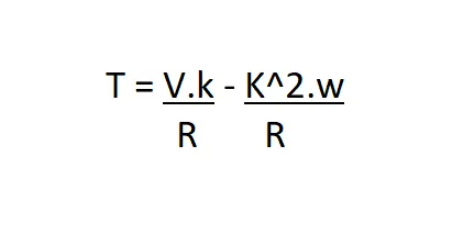
T = torque
V = armature voltage
R = resistance
w = speed rad/sec
Compare the two equations:
24.7 + 0.0051*w^2 = ((v*k)/R) - ((k^2)*w/R)
24.7 + 0.0051*w^2 = (72*0.7*0.7)/0.5 - (0.7^2/0.5)*w = 24.7 + 0.0051*w^2
70.56 - 0.98*w = 24.7 + 0.0051*W^2
w^2 + 192.15*w - 8992.15 = 0
In order to find the roots use following formula

As the speed value can not be negative
w = 38.95 rad/sec
Tv=24.7+(0.0051)*(38.95)^2.
Tv=32.43 sec.
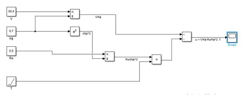
3.Develop a mathematical model of a DC Motor for the below equation using Simulink.
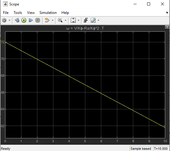
ωω= V/Kϕϕ -Ra/Kϕϕ^2 .T
Let us draw a model for the above equation.
Let V = 50.4 Volts
Kϕ= 0.7
Ra= 0.5Ω.
Model:-
Result:-
4.Explain in brief about author’s perspective
Wally Ripple is a long-time proponent of electric vehicles. Prior to joining Tesla Motors, he was an engineer at AeroVironment, where he helped develop the EV1 for General Motors and was featured in the documentary movie, Who Killed the Electric Car? Wally has also worked for the Jet Propulsion Laboratory on electric vehicle battery research, among other projects. In 1968, as a Caltech undergraduate student, he built an electric car (a converted 1958 Volkswagen microbus) and won the Great Transcontinental Electric Car Race against MIT.
Back in the 1990s all of the electric vehicles except one were powered by DC brushless drives. Today, all the hybrids are powered by DC brushless drives, with no exceptions. The only notable uses of induction drives have been the genral motor EV -1; the AC propulsion vehicles, including the tzero; and the Tesla Roadster .Both DC brushless and induction drives use motors having similar stators. Both drives use 3-phase modulating inverters. The only differences are the rotors and the inverter controls. And with digital controllers, the only control differences are with control code. DC brushless drives require an absolute position sensor, while induction drives require only a speed sensor; these differences are relatively small.
Indution Motor:-
The technology behind the induction motor is that it basically uses a 3-phase induction motor which was invented by Nikola Tesla sometime before 1889. Unlike the DC brushless rotor, the induction rotor has no magnets – just stacked steel laminations with buried peripheral conductors that form a “shorted structure.” Currents flowing in the stator windings produce a rotating magnetic field that enters the rotor. In an Induction motor current interacts with the Magnetic field generated by the stator to produce a force which is required for rotor torque.
When a 3-phase induction motor is connected to utility type 3-phase power, torque is produced at the outset. The fact that induction motors are directly compatible with conventional utility power is the main reason for their success.
Conclusion:-
- We have discussed and studied the different types of power converter circuits employed in electric and hybrid electric vehicles.
- EV Steady-state speed of an EV Drivetrain was determined with the given input conditions.
- The Mathematical model for DC motor is developed.
- To verify DC motor brushes wally ripple teshla motor.