Week-6 Challenge: EV Drivetrain
1. Which types of power converter circuits are employed in electric and hybrid electric vehicle?
The Function of a Converter
More properly called a voltage converter, this electrical device actually changes the voltage (either AC or DC) of an electrical power source. There are two types of voltage converters: step-up converters (which increases voltage) and step down converters (which decreases voltage). The most common use of a converter is to take a relatively low voltage source and step-it-up to high voltage for heavy-duty work in a high power consumption load, but they can also be used in reverse to reduce voltage for a light load source.
The overall management of electric vehicle load depends on the EV technology. There are two classifications in EVs as; plug-in hybrid EVs (PHEVs) and Battery EVs (BEVs) respectively.
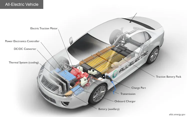
Battery electric vehicle (BEV)
On-board batteries are exclusively used to supply the desired power in BEVs which is illustrated in the figure 1.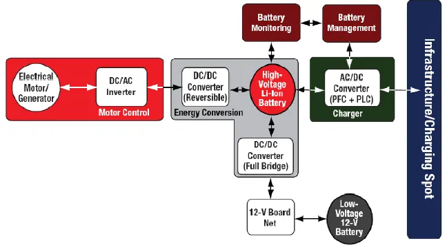
Figure 1
As it is shown in Figure, there is no feature of a combustion engine, and the vehicle is charged by plugging into the electricity grid. The overall drive systems of BEV are realized using an electric motor and a motor inverter. The coupling to the wheels is realized via a mechanic coupler (MC) and a transmission shaft (TR). The battery in the vehicle gets charged during driving and it will be useful while the EV is in regenerative braking. The only source of energy is the battery pack which is designed to fulfill a certain range.
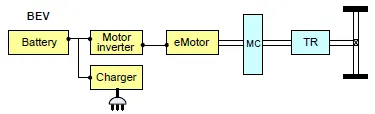
Plug-in Hybrid Electric Vehicle (PHEV):
It is a combination of ICE and electric vehicle, capable to charge using the grid and to operate over a short distance in battery mode and regenerative braking mode. The size of the battery in PHEV is smaller than the battery of BEV. However, the conventional engine and fuel tank are employed to extend the range. There are three different PHEV configurations available such as series-parallel hybrid, series hybrid, and parallel hybrid. Those PHEV configurations are depicted in Fig 2(a,b,c).
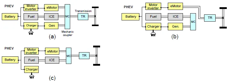
Fig 2 Plug-in Hybrid Electrical Vehicle
DC-DC converters for Electric Vehicles.
The DC-DC converters for electric vehicles are categorized into two types such as, unidirectional and bidirectional respectively. Fig.3 shows the different applications of DC-DC converters in EVs. In order to supply the onboard loads such as sensors, safety, utility, entertainment, and control equipment, the unidirectional DC-DC converters can be applied. These unidirectional converters are not only used to supply the on-board equipment and also to control DC drives in electric traction applications. The Bidirectional converters play important roles such as battery charging, regenerative braking, and back-up power. The power flow is bidirectional converters usually gets it from the low voltage side (battery or supercapacitors) to a high voltage side, which is basically defined as boost operation. During regenerative braking, the power flows from the high voltage side to the low voltage side (battery recharging), which is referred to as buck operation. These bidirectional converters are also used to supply the back-up power to the motor whenever if there is a malfunctioning or failures of internal combustion engines (ICE) or Electric drives. In order to drive the EV, basically, two different kinds of motors are used, which are AC and DC motors. In the early days of EV usage, DC motors are preferred due to their simple control mechanism. However, many different controlling techniques have been introduced to control AC motors in EVs. DC motors are usually used in the applications of the ropeway, locomotives, and steep trolleys. Whereas, AC motors are used in EVs and HEVs respectively. In recent trends, HEVs introduced by Toyota Prius and Honda Civic used permanent magnet synchronous motors. The PMSM has much better efficiency, high power density, and control by FOC (field-oriented control). A high voltage DC-DC converter supplies the desired voltage to the inverter and then its output drives the AC motors. The overall arrangement is shown in Fig.4
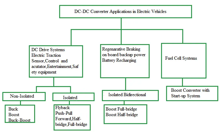
Fig 3 Applications of DC-DC converters in Electric Vehicles
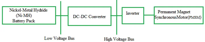
Fig 4 Power electronic circuit arrangement in HEV
Non-isolated converters
The non-isolated converters type is generally used where the voltage needs to be stepped up or down by a relatively small ratio (less than 4:1). And when there is no problem with the output and input having no dielectric isolation. There are five main types of the converter in this non-isolated group, usually called the buck, boost, buck-boost, Cuk and charge-pump converters. The buck converter is used for voltage step-down, while the boost converter is used for voltage step-up. The buck-boost and Cuk converters can be used for either step-down or step-up. The charge-pump converter is used for either voltage step-up or voltage inversion, but only in relatively low power applications.
Isolated converters
Usually, in this type of converters, a high-frequency transformer is used. In the applications where the output needs to be completely isolated from the input, an isolated converter is necessary. There are many types of converters in this group such as Half-Bridge, Full-Bridge, Fly-back, Forward, and Push-Pull DC/DC converters. All of these converters can be used as bi-directional converters and the ratio of stepping down or stepping up the voltage is high.
2. An Electric Vehicle's powertrain with 72V battery pack in shown in the diagram below. The duty ratio for acceleration operation is 'd1' and for the braking operation the duty ratio is 'd2'.
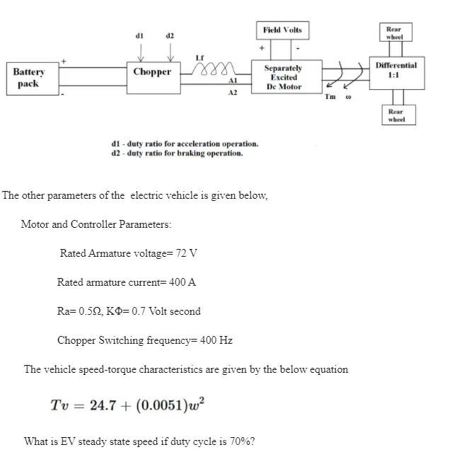
Solution:-
Armature Voltage, Varm = 72 V
Armature Resistance, Rarm = 0.5 Ω
Armature Current, Iarm = 400 A
Switching Frequency, fs = 400 Hz
Speed Constant, kΦ = 0.7 volt/s
The duty cycle is 70% it means 70% of time the switch is on position and 30% is on off position. Therefore the voltage at the output terminal is duty cycle * Armature voltage
The output voltage from the battery is = 72 * 0.7 = 50.4 v
The torque speed characteristic equation for the DC motor is
`T = (kphi)/(R_(arm)) *v - (kphi)^2/(R_(arm))*omega` ------------------------(i)
Where T is the torque ; is the angular speed in the rps ; Rarm is the armature resistance and is the speed constant.
The given vehicle speed – torque speed characteristics
`T = 24.7 + (0.0051omega^2)`
Equation the equation (i) and (ii)
`(0.7 * 50.4)/0.5 - (0.7^2)/0.5 *omega^2 = 24.7 +0.0051omega^2`
`0.0051omega^2 + 0.98 omega - 45.86 = 0`
Solve this quadratic equation
`omega_1 = 38.914 rps` and `omega_2 = -231.07 rps`
The –ve roots not satisfied the equation. Therefore the steady speed for the EV with 70% duty cycle is 38.94 rps.
3. Induction Versus DC brushless motors by Wally Rippel, Tesla
Explain in brief about author’s perspective.
- There are two types of motor available in the market (i) DC brushless and (ii) Induction motor.
- Both these motor have their own advantage and disadvantage.
DC Brushless machine
- The rotor includes permanent magnets that generate a DC magnetic field.
- The stator core is made up of a thin, stacked lamination.
- The current flowing in the winding of the stator core produces a magnetic field which interacts with the permanent magnet of the stator core and the opposite pole attracts with each other which produces torque in the rotor.
- To produce continuous torque the magnitude and polarity of the stator current be continuously varied.
- For the constant torque and for the right way of changing the polarity of the stator core, a sensor is used called an inverter. Without inverter the brushless motors are useless.
3-Phase induction motor
- 3 – Phase induction motor was invented by Nikola Tesla.
- The stator core has distributed winding similar to the DC motor stator core.
- There is no permanent magnet in the induction motor rotor, it is made up form stacked steel lamination with a peripheral conductor that forms a “shorted structure”.
- The rotating magnetic field is produced by the current flowing in the stator core.
- The rotating magnetic field induces a current in the rotor due to which constant torque produced and the rotor starts moving.
- The rotating magnetic field speed is called synchronous speed, the rotor tries to reach the synchronous speed and due to which there is a slip between the speed between the synchronous speed and rotor speed.
- When a 3 – Phase induction motor is connected to utility type 3-phase power, torque is produced and the motor has the ability to start under the load.
- No inverter is needed in the induction motor.
Difference between the Brushless or Induction
- DC brushless drives require an absolute position sensor, while induction drives require only a speed sensor
- Much less heat is produced in the brushless rotor. Rotor cooling is easier and peak point efficiency is generally higher for the brushless compared to the induction.
- Magnetic Fields are adjustable in the induction motor since B is proportionate to voltage/frequency. At light loads, the inverter can reduce the voltage so that magnetic losses are reduced and efficiency is maximized.
- As machine size grows, the magnetic losses increases proportionately and part load efficiency drops. With induction as machine size grows, losses do not necessarily grow.
- The induction motor is difficult to control. The control laws are more complex and difficult to understand compared to the DC brushless.
My conclusion is that DC brushless drives will likely continue to dominate in the hybrid and coming plug-in hybrid markets, and that induction drives will likely maintain dominance for the high-performance pure electrics.