Week-6 Challenge: EV Drivetrain
AIM: To understand and answer the following objectives:
1. Which types of power converter circuits are employed in electric and hybrid electric vehicle?
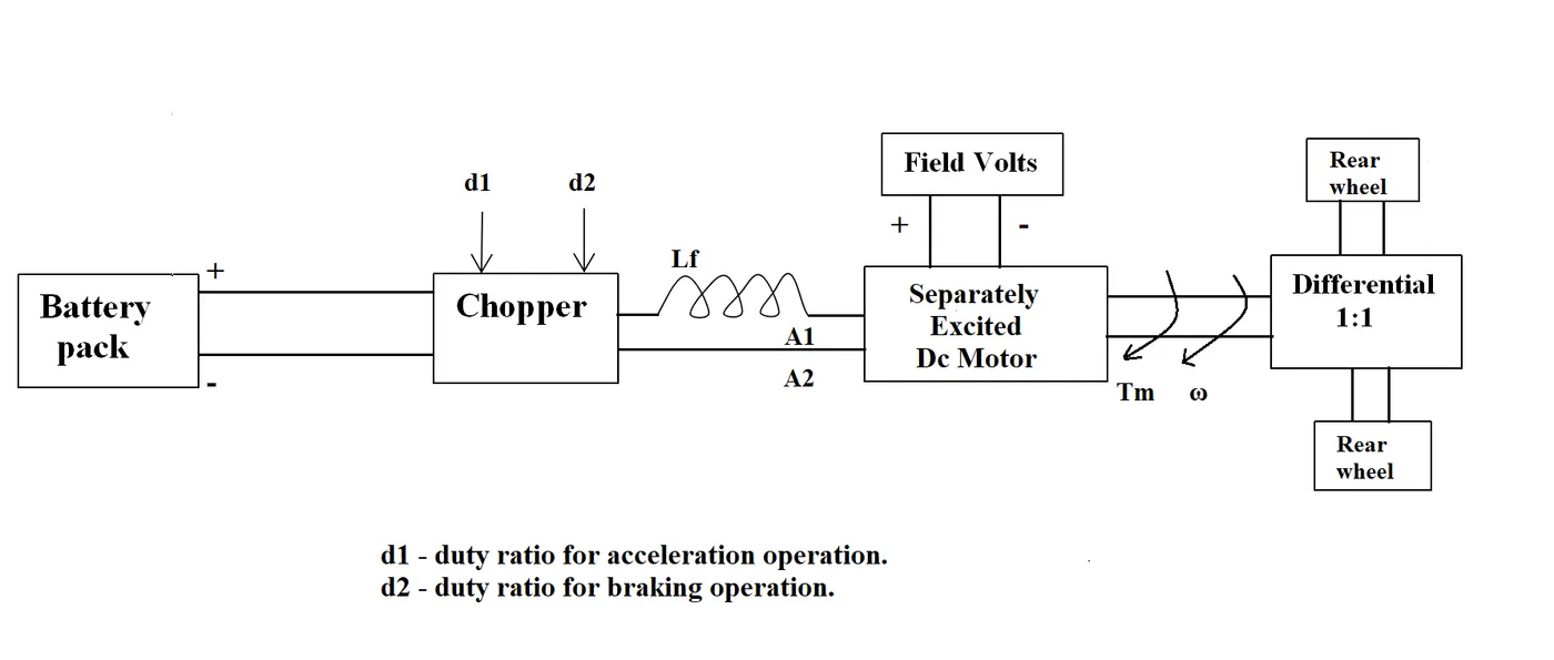
2. An Electric Vehicle's powertrain with 72V battery pack in shown in the diagram below. The duty ratio for acceleration operation is 'd1' and for the braking operation the duty ratio is 'd2'.
The other parameters of the electric vehicle is given below,
Motor and Controller Parameters:
Rated Armature voltage= 72 V
Rated armature current= 400 A
Ra= 0.5Ω, KΦ= 0.7 Volt second
Chopper Switching frequency= 400 Hz
The vehicle speed-torque characteristics are given by the below equation

What is EV steady state speed if duty cycle is 70%?
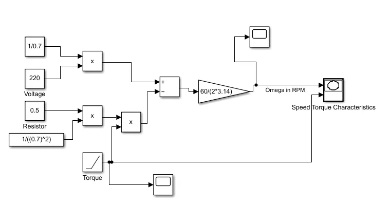
3. Develop a mathematical model of a DC Motor for the below equation using Simulink.
ω">ωω= V/Kϕ">ϕϕ -Ra/Kϕ">ϕϕ^2 .T
4. Refer to the blog on below topic:
Induction Versus DC brushless motors by Wally Rippel, Tesla
Explain in brief about author’s perspective.
METHODOLOGY
1. Which types of power converter circuits are employed in electric and hybrid electric vehicle?
Answer:
An electric motor drive encompasses power converter and controller.
Power electronic converter is used to handle the flow of bulk power from the source to the motor input terminals and controller in turn process the command input and feedback information to produce the switching signals for power converter semiconductor switches.
Power converter are mainly of two types namely a
DC drive supplying a DC motor
AC drive supplying an AC motor.
AC-DC converters are considered as electrical circuits that transform alternating current (AC) input into direct current (DC) output. (Controlled Rectifiers)
Application: Used in places where the power input 50 Hz or 60 Hz sine-wave AC voltage that requires power conversion for a DC output.
A DC/DC converter has a very high conversion efficiency and are operated at very high frequency. The switches are tuned ON and OFF by pulse width modulalion(PWM). The power converter consist of high power quick action semiconductors devices like bipolar junction transistor.
Step converters are classified into two types namely
Step up- When a low voltage input is converted into a high voltage output it is a step-up converter.
Step down- when a high voltage input is converted into a low voltage output it is a step down converter.
Other Types include:
- DC to AC Converter for Inverter applications - say battery to traction motors
- Static Switches
HEV & EV:
Electirc vehicles have clean energy sources like Fuel Cell (FC) stack, battery bank, and Super- capacitors (Xs). Thus, Advanced DC/DC , AC/DC and DC/AC converters are required for higher efficiency in conversion by adapting the output voltage and current levels with high power quality.
2. An Electric Vehicle's powertrain with 72V battery pack in shown in the diagram below. The duty ratio for acceleration operation is 'd1' and for the braking operation the duty ratio is 'd2'.
The other parameters of the electric vehicle is given below,
Motor and Controller Parameters:
Rated Armature voltage= 72 V
Rated armature current= 400 A
Ra= 0.5Ω, KΦ= 0.7 Volt second
Chopper Switching frequency= 400 Hz
The vehicle speed-torque characteristics are given by the below equation
What is EV steady state speed if duty cycle is 70%?
Solution:
Vehicle speed-torque Characteristics is given by the below equation
Torque Formula:
`T=(V.K)/R - (K^2.omega)/R`
Where;
T- Torque
V - armature voltage
R - resistance
`omega`- speed rad/sec
Combining both equations for Torque
`24.7+0.0051*omega^2=((v*k)/R)-((k^2)*omega/R)`
On simplifying and substituting the know values we get
`omega^2+192.15*omega-8992.15=0`
Solving the qudratic equation we get
'omega'=38.95 rad/sec
3. Develop a mathematical model of a DC Motor for the below equation using Simulink.

Solution:
Plot:
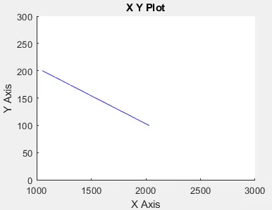
Inference: It is envisaged from the plot that As Torque increases in Y axis Speed decreases
4. Refer to the blog on below topic:
Induction Versus DC brushless motors by Wally Rippel, Tesla
Explain in brief about author’s perspective.
The author through his blog compares the type of motor that could be used in an Electric Vehicle and Hybrid Electric Vehicle.
Brushless DC Motor
In this case the rotor consists of 2 or more permanent magnets used to produce the Magnetic field DC. This field passes through the stator and interacts with flowing current within the windings to generate torque interactions between the rotor and stator. To maintain constant torque inverter is used. There is no starting torque in case of brushless DC motor so support from invertor is required. Phase is maintained in step with the angular position of motor.
Advantages:
Heat generation in rotor is less
Peak point efficiency is high
Has operation at Unity power factor so low consumption
Cons:
Due to fixed magnetic field Hysteresis and eddy current losses are higher
Not feasible when considered economical aspect
Higher Cost
Size is comparatively bigger size and as size increases magnetic losses increases and part load efficiency decreases
THREE PHASE INDUCTION MOTOR
It is made of steel laminations stacked with peripheral conductors forming a shorted structure. Unlike Brushless DC it does not have any permanent magnets. When rotating magnetic field produced by the current flowing through stator windings interacts with rotor emf is induced, Faraday’s Law. Torque is generated since rotor is a closed circuit.
Pros:
Compatible with conventional utility power
Hysteresis and eddy current losses are lower compared to Brushless DC motor. The magnetic field density can be varied by V/F Control
Suitable for high performance application as with increase in size, increase in losses is minimal
Cost is comparatively cheaper
Average Efficiency is high
Cons:
Rotor Heat generation is higher in comparison due to difficulty in realizing a cooling method
Max Power factor is only 85%
Lower efficiency compared to Brushless DC motor
Conclusion: Brushless DC will dominate HEV and Induction motor will dominate the high performance EV.