Power electronics and Ev drive train applications
Introduction to power electronics in Ev Drive train
In this project, we are going to study various types of power converter devices used in an electric vehicle and will understand briefly their workings.
Depending on the usage the power type requirement varies inside an electric vehicle. some components may work on an AC supply while others may require a DC current input. Some component needs less voltage while others need the full battery potential. Depending upon the usage a microcontroller of an electric vehicle may require to perform all these functions within a fraction of seconds in order to keep the operation smooth.
Depending on the type of function performed, power electronic converters are categorized into the following types.
- AC to DC = Rectifier: It converts AC to unipolar (DC) current
- DC to AC = Inverter: It converts DC to AC of desired frequency and voltage
- DC to DC = Chopper: It converts constant to variable DC or variable DC to constant DC
- AC to AC = Cycloconverter, Matrix converter: It converts AC of the desired frequency and/or desired voltage magnitude from a line AC supply.
AC to DC Rectifier - An AC to DC converter, also known as a rectifier, converts alternating current (AC) supply from main lines to direct current (DC) supply for the load. The rectifier's essential components include a transformer, a switching unit, a filter, and a control block.
The transformer modifies the primary AC source supply to the rectifier stage's input. Typically, a step-down transformer is used to reduce the supply voltage to a circuit operating range.
The rectifier converts the low voltage AC supply to a direct current supply.
Depending on the type of rectifier, it is made up of diodes and/or thyristors. Because the rectifier's output is pulsed DC, it must be filtered using a filter circuit, which is typically comprised of a capacitor or a choke.
The diode rectifiers are classified into the following types.
- single-phase half-wave rectifier
- single phase full wave bridge rectifier
- Three-phase half-wave rectifier
- Three-phase full-wave rectifier
DC to DC inverter -
Many DC-powered applications require varying levels of DC voltage from a single DC source.
Subway cars, DC traction systems, control of large DC motors, battery-powered vehicles, trolleybuses, and other applications are examples of these. They require variable DC to produce variable speed, which necessitates the use of a power conversion device.
A DC chopper is a fixed device that converts a fixed input DC voltage to a variable DC output or a fixed DC output with a different magnitude (that can be lower or higher) than the input value.
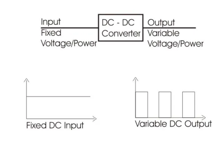
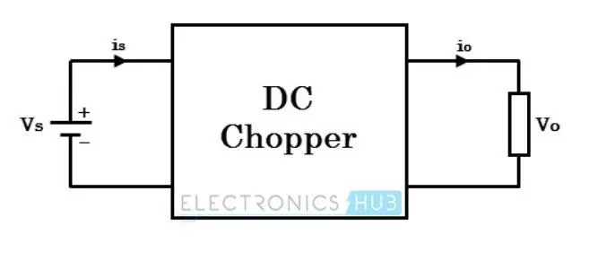
The chopper circuit is connected between the direct current input source and the direct current load. This chopper is made up of power electronic switching devices such as thyristors that are wired together to produce the required DC voltage to the load.
The output voltage is controlled by altering the ON time of the thyristor (or switch), which changes the width of the DC voltage pulse at the output. This switching method is known as pulse width modulation (PWM) control.
The chopper's output can be less or greater than the input, and it can also be fixed or variable. Depending on the design, these can be unidirectional or bidirectional devices.
DC choppers are most commonly found in DC drives. i.e HEv or Electric drive vehicles.
AC to AC Converter -
AC/AC converters connect an alternating current (AC) source to an alternating current (AC) load by controlling the amount of power delivered to the load. This converter changes the magnitude and frequency of the supply voltage to convert the alternating current voltage from one level to the other.
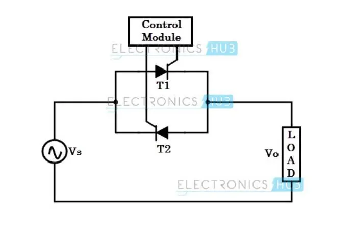
When the triggering is applied, thyristor-1 is forward biassed during the positive half cycle of the input signal and begins conducting. As a result, power flows from source to load.
Thyristor-2 is forward biassed in the negative half cycle of the input and begins conducting when triggered, whereas thyristor-1 is turned OFF.
DC to AC Converter -
These converters are connected between a fixed-input DC source and a variable-input AC load. These DC to AC converters are commonly referred to as inverters. An inverter is a fixed device that converts a fixed DC supply voltage to variable alternating current voltage.
In most power electronic converters, the fixed DC voltage is obtained from batteries or via a DC link. The inverter's output can be variable/fixed AC voltage with variable/fixed frequency.
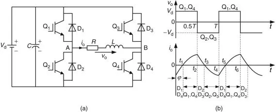
The figure depicts a single-phase full-bridge inverter with four power switches: Q1–Q4. The switch pairs (Q1, Q4) and (Q2, Q3) operate sequentially. The load's two terminals are connected to the middle points of the bridge circuit's left and right legs, respectively. The load under consideration is an RL load with an impedance phase angle of Furthermore, four diodes, D1–D4, are used to provide paths for the load current, which is driven by the stored energy in the load inductor. T denotes the period of a cycle.
Application of Chopper motor characteristics in an Electric vehicle.
Aim - In this project, we are going to find the Steady speed for an Ev motor with the following data.
Input -
An Electric Vehicle's powertrain with a 72V battery pack is shown in the diagram below. The duty ratio for acceleration operation is 'd1' and for the braking operation the duty ratio is 'd2'.
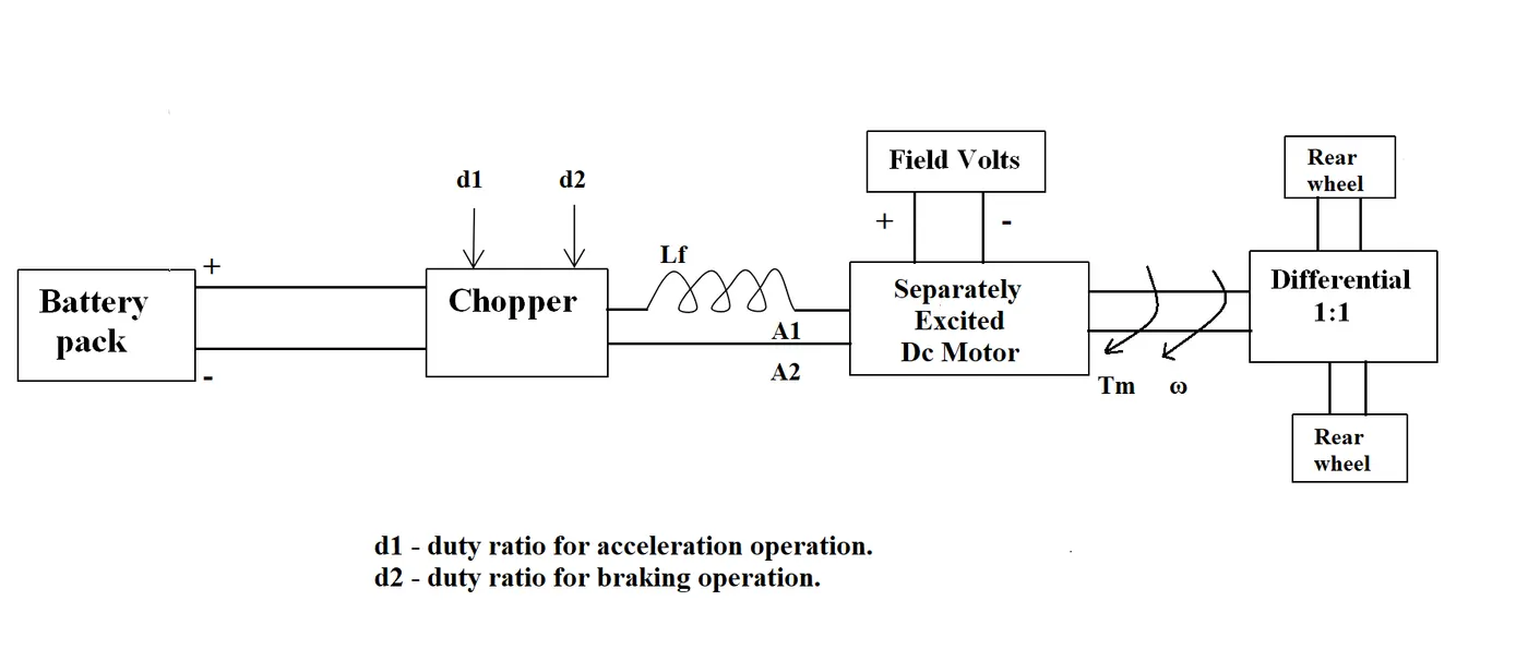
The other parameters of the electric vehicle are given below,
- Motor and Controller Parameters:
- Rated Armature voltage= 72 V
- Rated armature current= 400 A
- Ra= 0.5Ω, KΦ= 0.7 Volt sec
- Chopper Switching frequency= 400 Hz
- The vehicle speed-torque characteristics are given by the below equation

- Duty cycle - 70%
At 70% duty cycle the voltage input for the motor is 50.4 V
We know that,
`T = (V.Kphi)/(Ra)-(Kphi)^2/(Ra)*omega`
putting the values in the above equation
`T = 70.56-0.98*omega`
In order to attain the steady-state, the Vehicle torque must be equal to the Motor torque value.
i.e,
`70.56-0.98*omega=24.7+(0.0057)*omega^2`
Solving the above equation we get a quadratic equation,
`0.0051omega^2+0.98omega-45.89`
Using
`-b+-root()(b^2-4ac)/(2a)`
we get,
`(-0.98+-root()(0.98^2-4*(0.0051)*(-45.89))/(2*0.0051))`
`omega = 38.92 (rad)/s`
Mathematical model of Motor speed-torque characteristics equation using Simulink
In this project, we are going to develop a simple mathematical model of the motor speed-torque characteristics equation and will study the results.
Tools used -
- MATLAB Simulink
Block Used -
- Constant
- signal builder
- scope
- square
- multiplication
- division
- subtraction
Model -
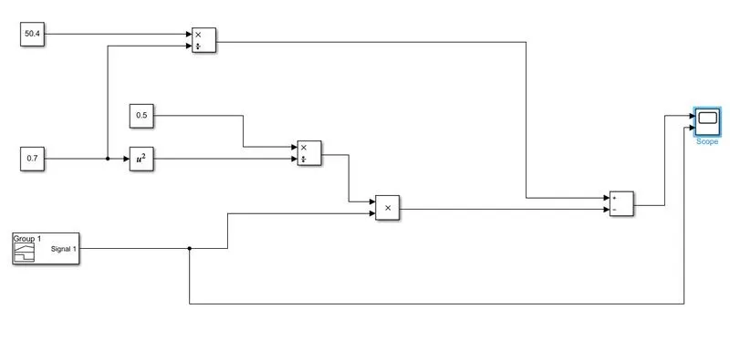
Input data -
- Torque signal
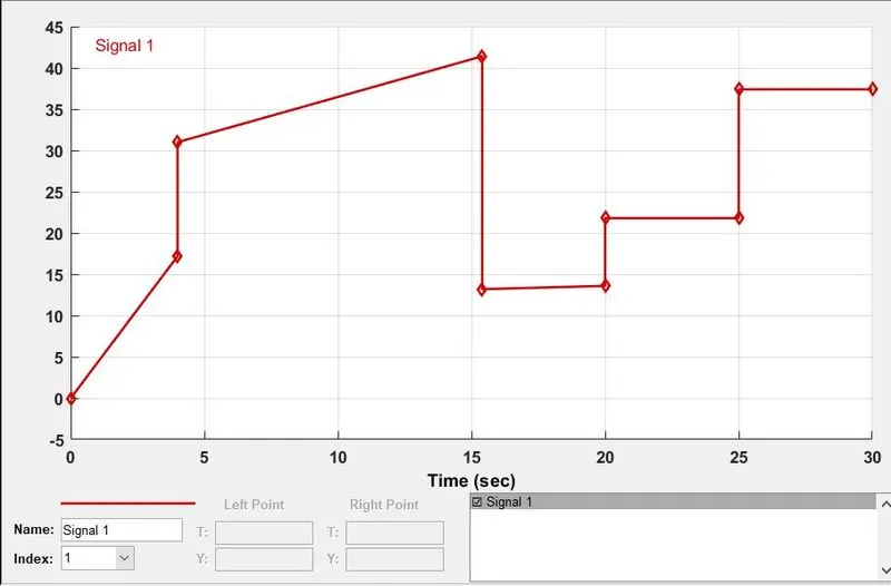
- Voltage and Armature resistance are taken from the previous model
Output -
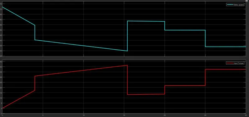
Conclusion -
- The red line indicates the input value of torque
- The blue line indicates the motor speed
- By putting 2 graphs side by side we can see the Torque is inversely proportional to motor speed. As the motor torque increases the speed decrease and vice versa.
A brief explanation of Wally Ripple's article on DC brushless motor and Induction motor.
Wally ripple is the principal power electronic engineer at tesla. Before joining tesla he worked with GM in the development of GM EV 1, because of his extensive experience in the industry he has pretty interesting thoughts on Brushless and Induction motors.
- in the case of a DC brushless motor the stator is made up of winding coils but the rotor is made up of permanent magnets.
- Whereas in the case of induction motors the rotor is made up of a laminated steel plate on which emf is induced whenever the polarity in the stator coil is changed.
- The peak power is more in the case of a DC brushless motor and heating is less as compared to that of an Induction motor. in an Induction motor, a peak efficiency of 85 percent can be achieved only.
-However, both DC and Induction motors are used heavily in the Ev market and are going to be present in long run. depending on the budget and power requirements we can switch between dc brushless and Induction motors.
Model link - https://drive.google.com/drive/folders/1iP4mNbxvr3ldmlQbyWeJGGCyPxc2qP4K?usp=sharing