Meshing Hood Geometry of a car
OBJECTIVE:
- Generate mid surface and perform geometry clean-up of the component
- Generate mesh with low tria concentration and proper mesh flow
- Satisfy all the below given quality parameters
Target Element Size = 5mm
|
S.N |
Quality Criteria |
Value |
|
1 |
Aspect Ratio |
5 |
|
2 |
Skewness |
45 |
|
3 |
Warping |
15 |
|
4 |
Taper |
0.5 |
|
5 |
Min. Length |
2 mm |
|
6 |
Max. Length |
8 mm |
|
7 |
Min angle Quad |
45 |
|
8 |
Max angle Quad |
135 |
|
9 |
Min angle Tria |
20 |
|
10 |
Max angle Tria |
120 |
|
10 |
Tria % |
10 |
SOLUTION:
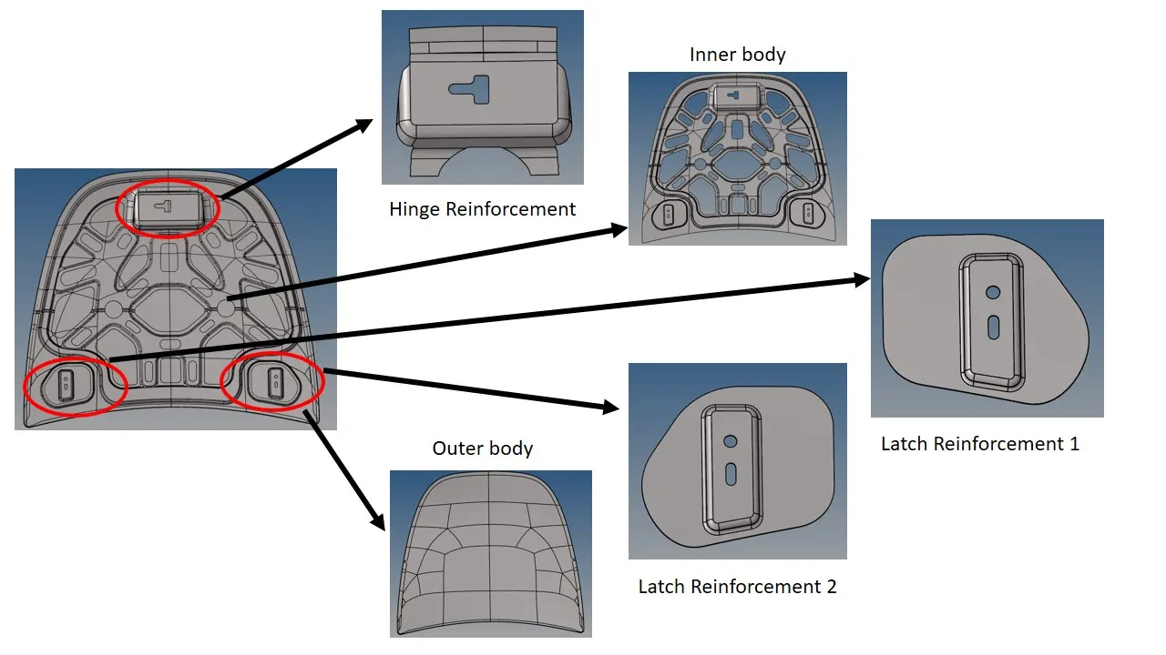
The objective of the project is to perform proper meshing of the given component. The component provided for the task is named Hood and is made of five different parts. For performing proper meshing of the component, each of these parts needs to be separated and meshed individually. The mid surface of each parts has to be extracted and geometry clean-up needs to be performed on each of the parts. The meshing should be done using quad elements and maintaining minimum tria element concentration. The final mesh has to satisfy all the given quality parameters and should have a god mesh flow.
Step 1:
The Hood is made of Outer body, Inner body, two Hinge reinforcements and latch reinforcement. After importing the Hood model into the Hypermesh GUI, each of these parts were separated and saved in a different file.
Step 2:
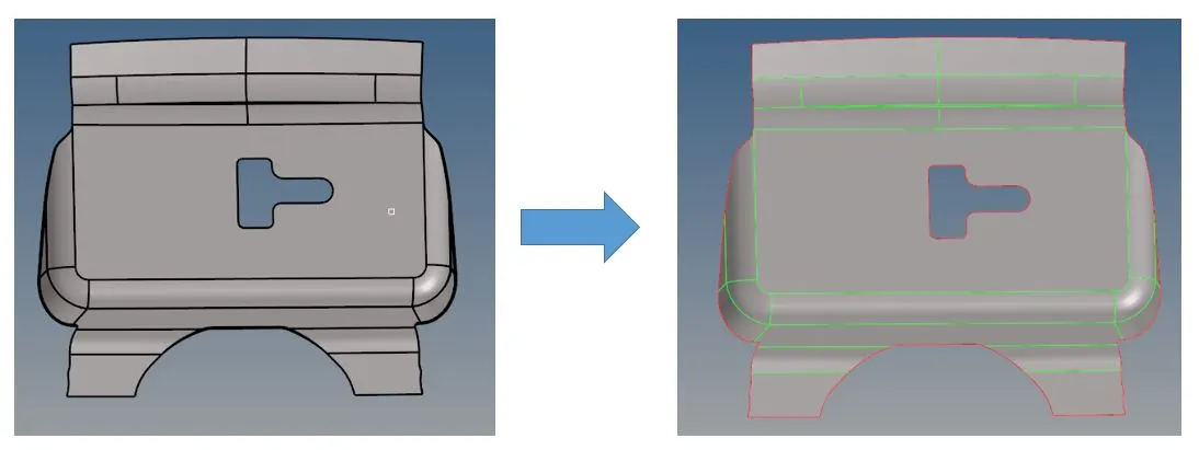
The part is loaded into the GUI and the mid surface of the component was extracted. This was done using the midsurface tool in the Geom panel. In extraction option, skin offset was selected and the autoextraction was performed. An example of this is shown in below diagram.
Step 3:
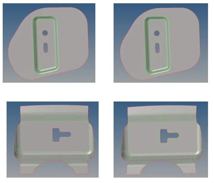
After extracting the mid surface, the geometry clean-up of the surface was carried out. For this autocleanup option in the Geom panel was used. The given parts have multiple hole features of varying shapes in the geometry. When the meshing is performed, it is highly probable that the surfaces adjacent to these features is not captured properly. To better capture the geometry, washer splits are created around these features, so that the area covered inside these lines is given a dedicated mesh flow. Further, depending on the feature geometry and size of the component multiple split line may be provided around the features. This was done using the quick edit option in the Geom panel. The size of the washer splits can be decided by taking into consideration the target element size. Here the value was maintained as 5mm for all washer splits created.
Step 4:
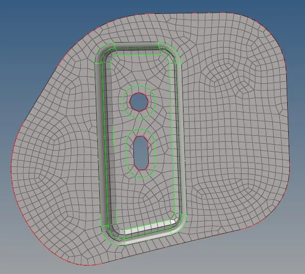
The mesh was created using quad element of 5mm size using the automesh option in 2D panel. An example of the initial mesh generated for a component is shown below. This is a computer generated mesh and requires clean-ups to satisfy the quality parameters and for good mesh flow.
Step 5: Mesh clean up
The mesh generated is supposed to have a good flow and satisfy all quality criterions. Some steps to achieve the same is as described:
- Some modification in the mesh can be brought by controlling the changing the number of elements at the different sections. This action can be performed at the initial step of meshing.
- For removing local element concentration and to imparting good mesh flow, the elements in these areas may be selected and meshed again. Sometimes, multiple iterations may be required to get a good mesh.
- For generating the mesh of required quality, various tools are available in the qualityindex and elem cleanup options in 2D panel.
- Some commonly used tools for generating good quality mesh includes element optimize, place nodes, combine tria elements, split quad elements, cleanup, automesh, check elements and so on.
Step 6: Material and Property
The material for components were selected as Steel and the material parameters were defined. Further, a thickness of 2.5 mm was defined for all components. This can be done by creating a thickness property and assigning it to the component.
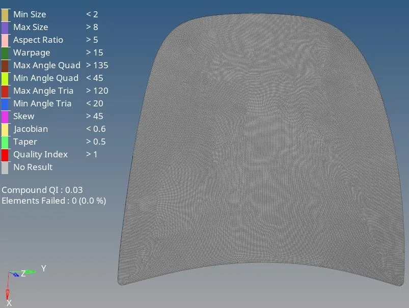
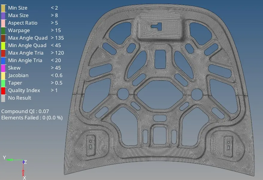
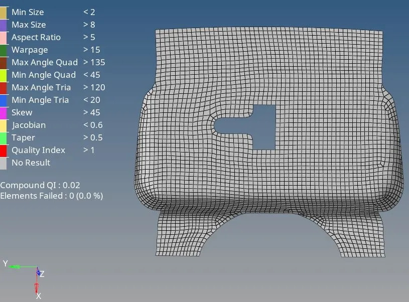
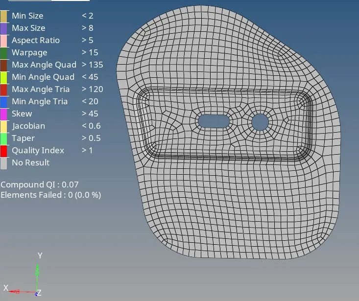
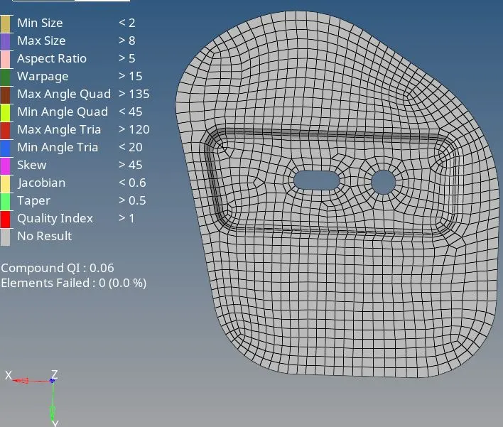
The different meshed parts of the component are as shown:
Conclusion:
- The different parts from the given components were separated and meshed.
- The mid surface for each component was extracted and geometry cleanup was performed on the part. Washer splits were provided wherever necessary.
- All parts were meshed using quad elements and the mesh was modified to get good mesh flow.
- Further each quality parameter, as defined in the problem statement, was cross checked and necessary changes were incorporated into the mesh.
- Each of the components were assigned steel as the material and the thickness of the parts were defined as 2.5mm.