Week 6 Challenge
Aim:- To analyze and design the bridge underpass raft foundation considering, earth pressure,self-weight, Surcharge, Braking loads.
Modeling in STAAD-Pro:-
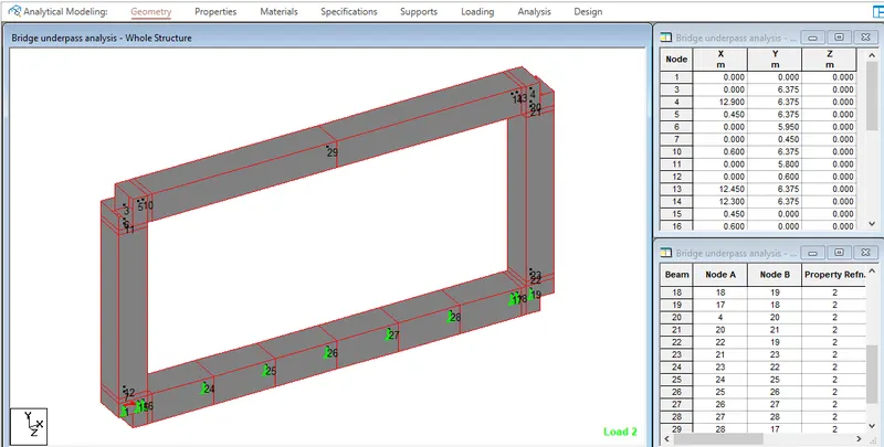
The bridge underpass is modeled as a plane frame structure taking the centerline dimension of the structure in STAAD-Pro. As the length of the underpass is more than twice its width, the box will be analyzed for unit length and the design will be adopted for the entire length. Loads corresponding to the unit length are evaluated and the structure is analyzed and designed. Since the box is fully resting on the soil, discrete spring supports are provided below the base on a sub-grade modulus of the soil available at the base. The sizes of the member are assigned accordingly in the model.
STAAD-Pro Model:-
Loading on the structure
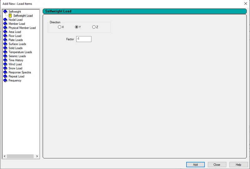
Self-weight of the base slab
The sizes of the members are given below:-
| The thickness of the top slab | 0.85m |
| Height of top haunch | 0.15m |
| Clear height | 5.5m |
| Width of the Underpass | 12m |
| Height of bottom haunch | 0.15m |
| The thickness of the bottom slab | 0.9m |
| The volume of the bottom slab is | 0.9x1x(12+0.9+0.9) = 12.42 m^3 |
| Weight of bottom slab | 12.42x25=310.5 kN |
Earth Pressure:-
| Angle of repose | 30 degree |
| At rest earth pressure co-efficient | 0.5 |
| Density of soil | 20 kN/m^3 |
| Height from the top (m) | The intensity of earth pressure (kN/m^2) |
| 0.425 | 4.25 |
| 0.85 | 8.5 |
| 1 | 10 |
| 6.2 | 62 |
| 6.35 | 63.5 |
| 6.8 | 68 |
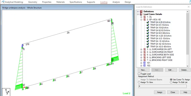
The earth pressure acting on the structure is assigned as trapezoidal on both sides of the box structure in staad.
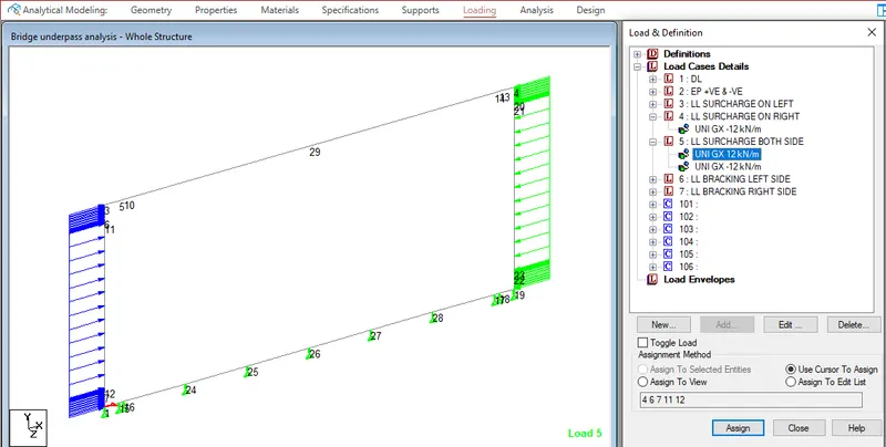
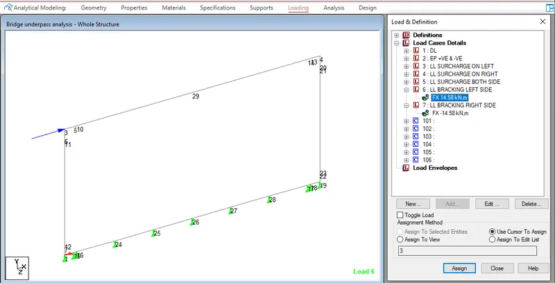
Similarly, the live load surcharge and braking loads are applied using specific load commands
Live load surcharge:-
| Equivalent height | 12 | |
| Intensity of loading | 1.2*20*0.5 | 12 kN/m^2 |
Braking load
| Max. Live load on the box | 700 kN |
| Width of the box | 12m |
| Braking load | 14.58 kN |
Load combination
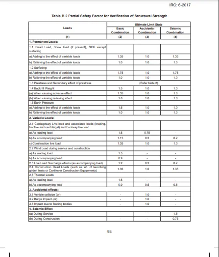
Partial safety factors for the ultimate limit state are considered as per IRC 6. The following loaded combinations are used.
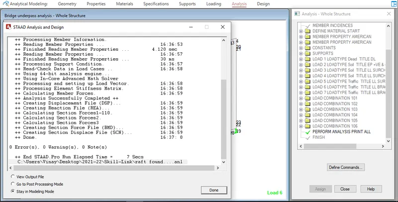
The analysis is carried out using STAAD-Pro
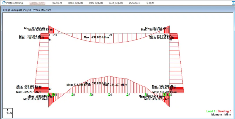
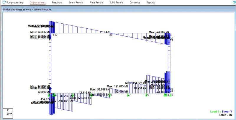
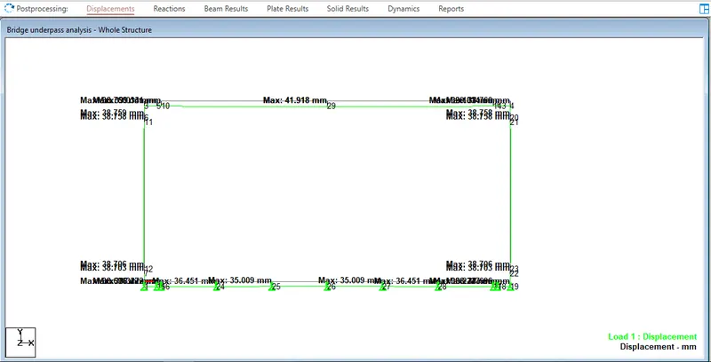
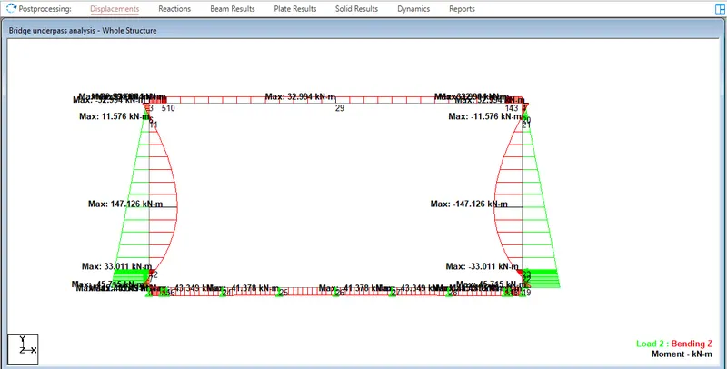
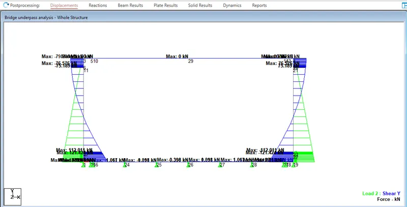
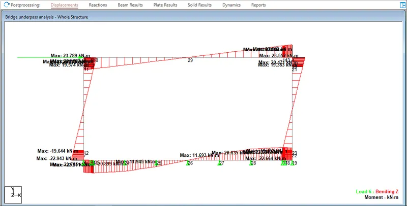
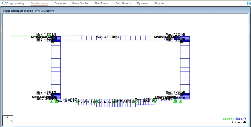
From the analysis results, a critical case of the load values is adopted for the design. The bending moment will be maximum at the center of the base slab. For the worst combination, design has to be carried out. The critical section for shear will be at the distance "d" from the face of the support. The bending moment, shear force and deflection diagram are given below.
Analysis Results
| Load | Bending Moment, Mz, (kN.m) | Shear Force, Fy, (kN) |
| Dead load | 398.83 | 232.11 |
| Earth Pressure | 41.38 | 1.07 |
| Live load Surcharge | 12.98 | 17.8 |
| Braking | 11.94 | 6.06 |
Bending moment, Shear force & deflection diagram.
DEAD LOAD
EARTH PRESSURE.
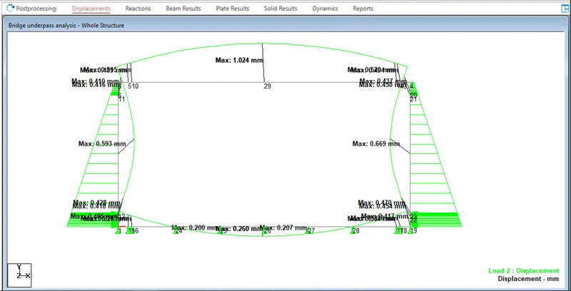
LIVE LOAD SURCHARGE.
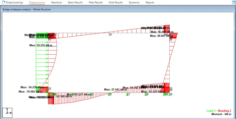
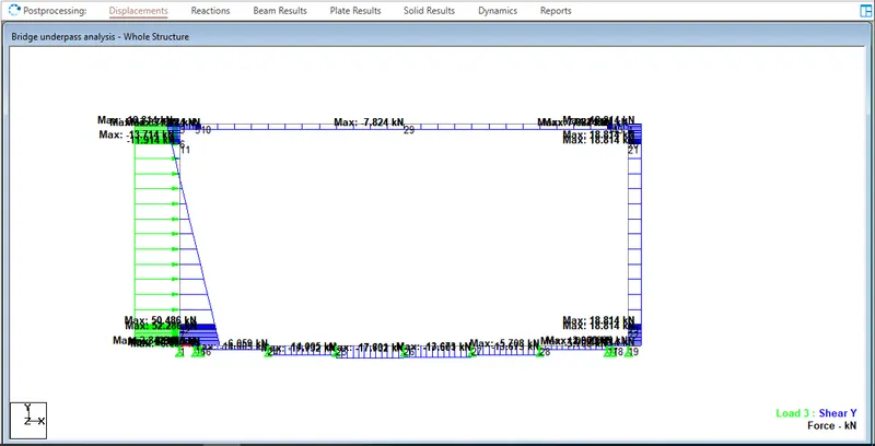
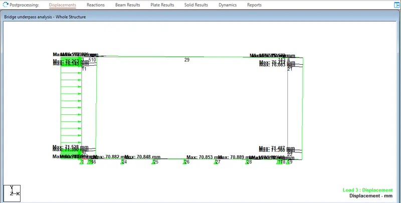
BRAKING LOAD

2. Design of the member based on the analysis and indicate the selection of the member size.
The members of the underpass i.e., the top and bottom slabs and vertical walls are designed as the beam members subjected to axial thrust and flexure. The assumed dimensions of the sections are for adequacy of the reinforcement provided and stresses in the concrete and reinforcing steel.
Using the load combination, Bending moment envelops for the structures are obtained. For the maximum B.M corresponding, axial forces are picked out from the STAAD post-processor.
| Max factored bending moment | 470 kN.m | |
| Max factored shear force | 320 kN | |
| Depth of base slab, D | 900 mm | |
| Width of base slab, b | 1000 mm | |
| Grade of concrete | M30 | |
| Grade of steel | Fe500 | |
| Es | 2x10^5 Mpa | |
| Ecm | 31000 Mpa | |
| Design yield strength of shear reinforcement | Fywd=0.87fyk/Ys | |
| 0.8*500/1.15 | ||
| 348 Mpa | ||
| Material safety factor | ||
| Concrete | 1.5 | |
| Steel reinforcement | 1.15 | |
| Ultimate compressive strain in concrete | 0.035 up to fck | |
| Modular ratio | 6.45 | |
| Long term modular ratio | 12.9 | |
| Ultimate tensile strain in steel | 0.00217 | |
| Coefficient, | 0.67 | |
| Factor, lamda | 0.8 | |
| Eta | 1 | |
|
13.4 Mpa | |
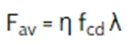 |
10.72 | |
 |
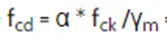
0.42 | |
| The effective depth of the member | 900-50-10 | |
| 840 mm | ||
| M/(bd^2*Fav) | 470*10^6/(1000*840^2*10.72) | |
| 0.062 | ||
| Limiting NA depth, Xlim | 840*0.0035/(0.00214+0.0035) | |
| 518.52 mm | ||
| Force in compression=Force in tension | ||
| fy*As/Ys=n*fcd*λx*b=Fav*x*b | ||
| M=Fav*x*b*(d-bx) | ||
| Which gives, x= d(1-√(1-4bkav))/2b | ||
| 53.44mm<518.52 mm | ||
| Required reinforcement area, As= 1.15*10.72*53.44*1000/500 | ||
| 1317.6 mm^2 | ||
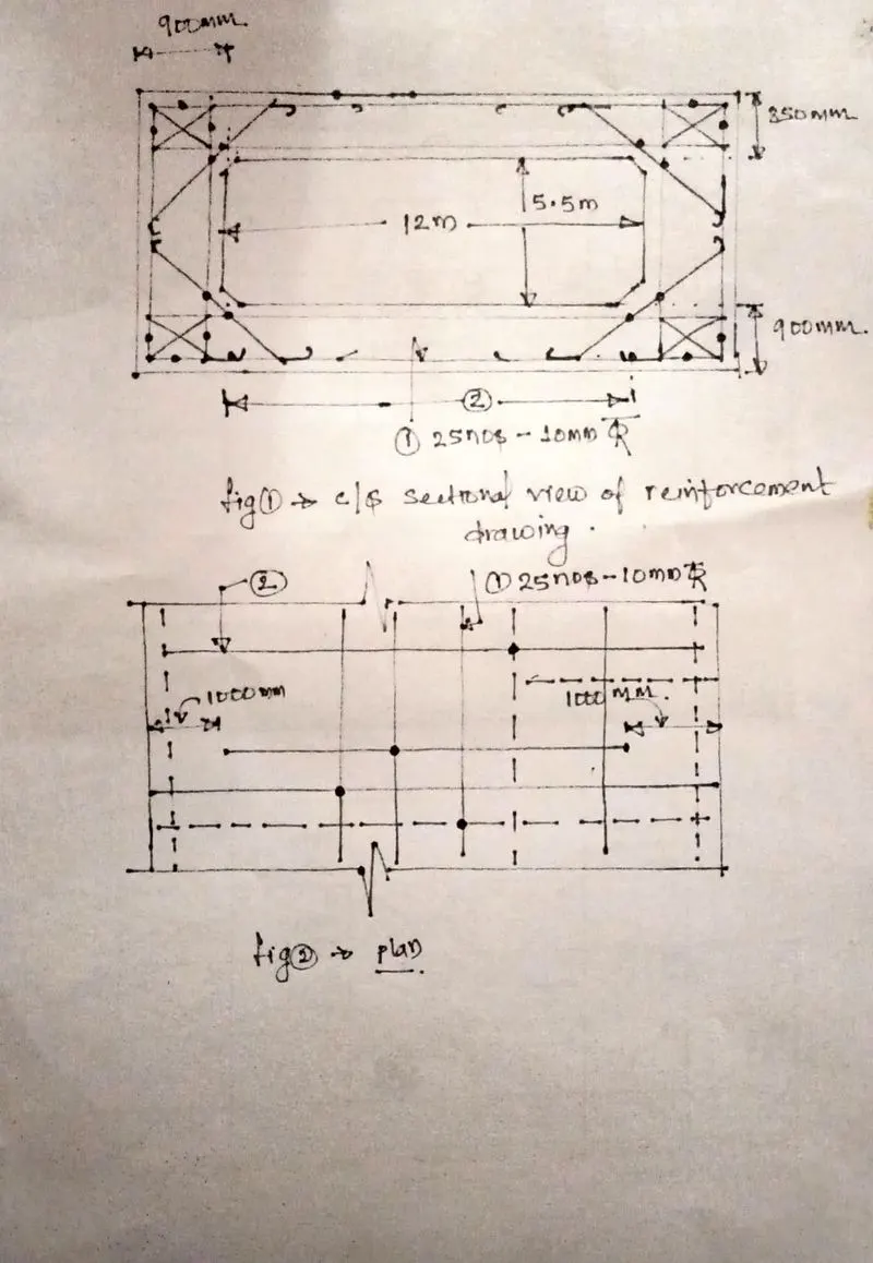
| Provide 10 mm reinforcement 25 nos | ||
| Providede reinforcement= 1963 mm^2> 1317.6 mm^2 | ||
| Hence ok | ||
| Neutral axis depth, | 79.62mm<518.52 mm | |
| Hence ok | ||
| Xlim/d | 518/840 | 0.617 |
| Rlim | 4.98 | |
| Effective depth required | √(Mu/(Rlim*b)) | |
| 307 mm<900mm | ||
| Hence safe | ||
Selection of member size:-
The size of the base slab depends upon factors such as the height of the bridge, uplift pressure acting on the foundation, soil fill on the top of the box.
When the height of the bridge is more, the size of the member required will be more because of the increase in lever arm as well as force. In such cases, the forces can be reduced by reducing the height of the structure and providing fill on top. The hydrological parameter should be taken into account in this case.
To avoid uplift, the size of the base slab can be increased. Alternately, the length of the raft slab can be increased. This will result in an increase in uplift but can be compensated by the earth from the top. The more the fill on the top slab, the proportion of the raft foundation is more. Generally, span/10 is adopted for selection of base slab thickness, later it can be optimized seeing design and economy. While determining the member sizes feasibility, safety, hydrology, and site criteria should also be observed.
3. Reinforcement detailing in the base slab.
4. To analyze the change in shear in the base slab if there is a 5m fill
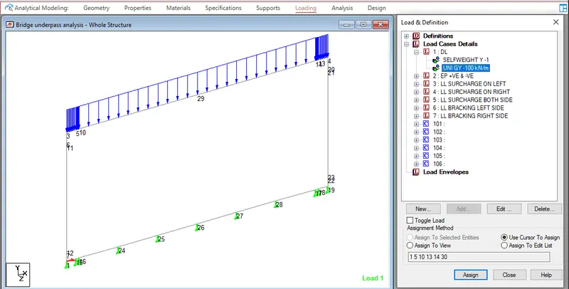
SIDL due to earth fill
The thickness of the earth fill on top is 5m
The density of fill material 20kN/m^3
UDL due to earthfill 100kN/m
It is applied as a dead load on top, uniformly distributed throughout the width of underpass.
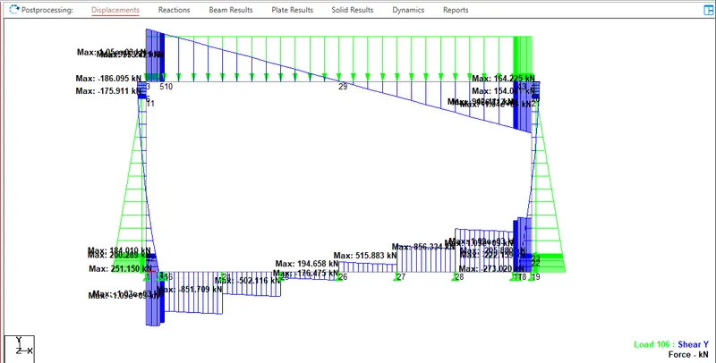
After analysis, the design shear force is taken as 1096 kN
Shear Design:-
Shear force= Ved=0.5*bw*d*v*fcd; = 0.5*1000*840*16.26*13.4; = 91511.3 kN
Where v is the strength reduction factor
Longitudinal force=0kN
Shear force by shear reinforcement = Vrds= Asw*z*fywd*cot(theta)/s
Shear resistance of the section without shear reinforcement
Vrdc= 0.12k(80ρ1fck)^0.33+0.15σc*ρ*bw*d
K=0.522
Vmin=0.031*k^3/2*fck^1/2; =0.064
ρ1= Ast/bw*d; = 0.0023
Vrdc=100.937 kN
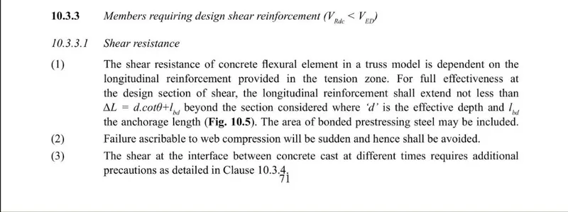
Hence share reinforcement is required
Vns=Vrd.max
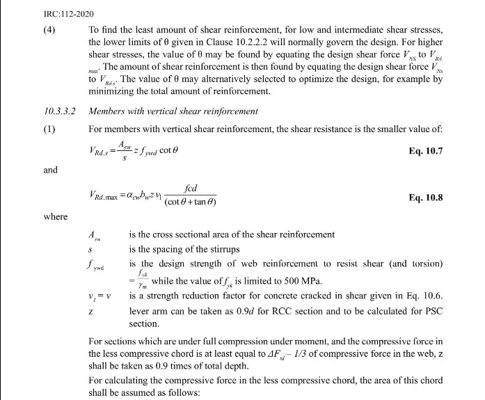
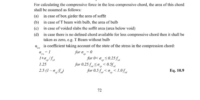
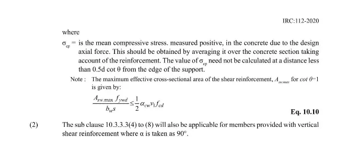
The diameter of the bar used as shear reinforcement is 2 legged 10 mm
Shear force by shear reinforcement Vns
Spacing 190 mm c/c
Provide shear reinforcement vertically 2 legged 10mm dia @ 190 mm c/c.
b. To analyze the change in shear in the base slab if there is a 0m fill
After analysis, the design shear force is taken as 339 kN
Shear Design:-
Shear force= Ved=0.5*bw*d*v*fcd; = 0.5*1000*840*16.26*13.4; = 91511.3 kN
Where v is the strength reduction factor
Longitudinal force=0kN
Shear force by shear reinforcement = Vrds= Asw*z*fywd*cot(theta)/s
Shear resistance of the section without shear reinforcement
Vrdc= 0.12k(80ρ1fck)^0.33+0.15σc*ρ*bw*d
K=0.522
Vmin=0.031*k^3/2*fck^1/2; =0.064
ρ1= Ast/bw*d; = 0.0023
Vrdc=100.937 kN
Hence share reinforcement is required and should be provided as per IRC 112-2020.
Vns=Vrd.max