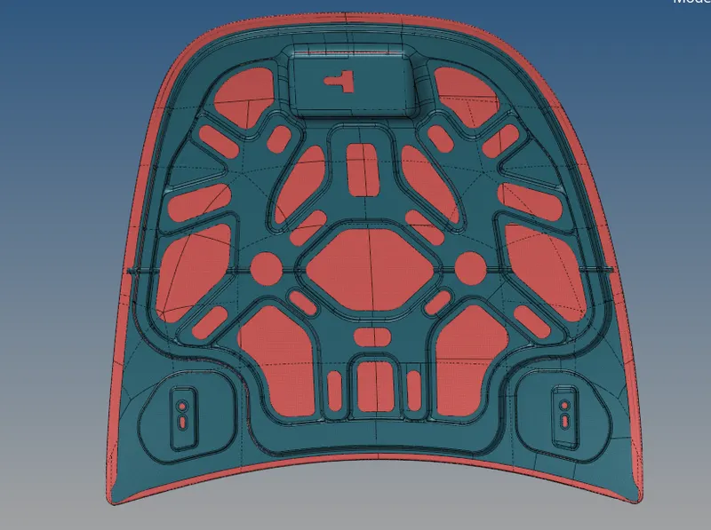
Creating Mid surface, Geometry Cleanup, Meshing and Quality Check on Hood model by using HYPERMESH
AIM :
To Preprocessing the given hood component and created mesh should pass all the quality parameters.
OBJECTIVES :
1) Extracting the midsurface individually in each part from which given parent component.
2) To cleanup the extracted midsurface by using both automatic as well as manual.
3) Discritization on extracted individual midsurface.
4) Checking the mesh quality as per given quality criteria.
CAD MODEL IMAGE :
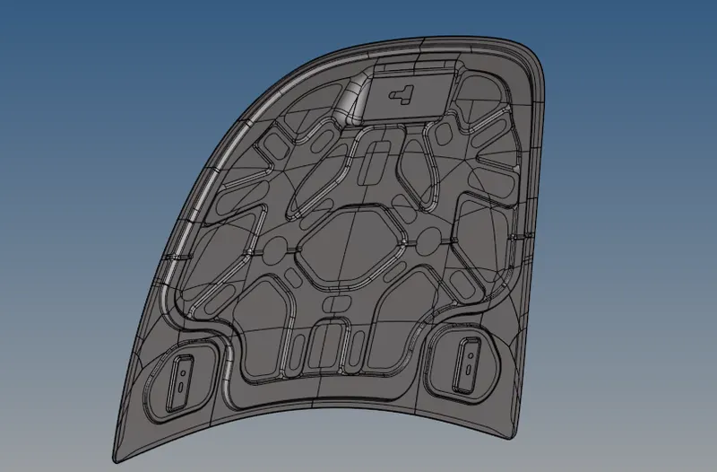
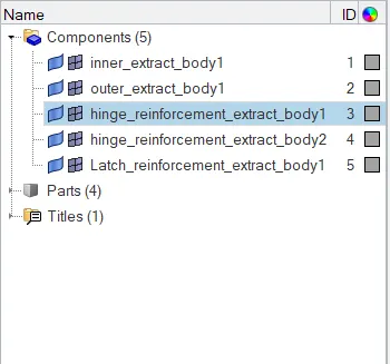
1) Open a Hyperworks software then click the 'Import Solver Deck' option, then select the option called 'Import Geometry' afterwhere choose the file type which is 'STEP' Format. Because, given file format is 'STP file' and then select the appropriate file which we want perform afterthat click 'Import option'. After importing the file, a component should shows same as below snap.
2) A Model contains five components are One Latch, two Hinge, Inner body and then outer body.
PROCEDURE FOR ATTENDING THE OBJECTIVES :
A given hood model have five components, initially importing the model all component were visible to see from graphical display. Inorder to extracting the midsurface one by one, we have to unselected the 'component visible option' for all components except one components for which performing on it.
i) Latch Reinforcement component :
Delete Solid part :
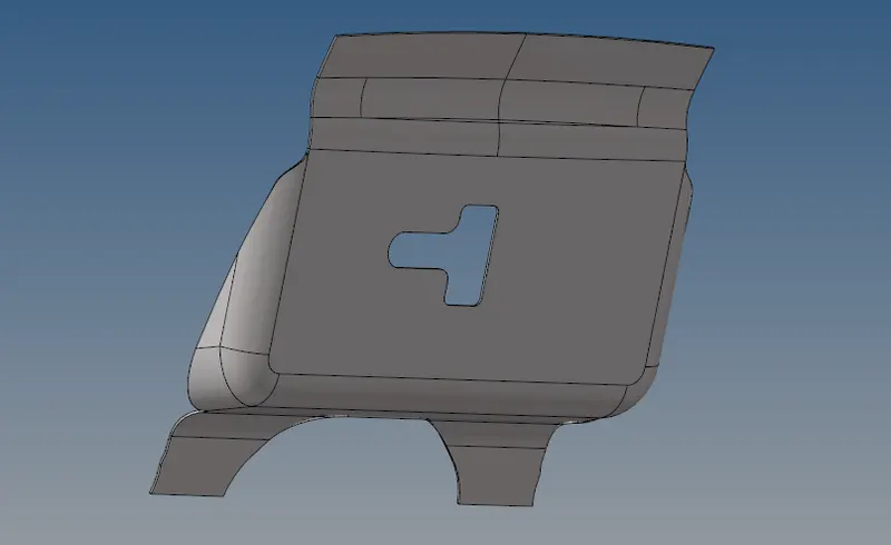
1) After select the latch component, it will showing the component from hyperworks window. This component is a solid part, we need only surface for extracting the midsurface from that Latch component. So, we has to delete the solids by using delete option.
2) Click the 'Delete option' from tool bar or else press F2 from the keyboard. Choose the 'Solid' from selector bar then selecting the solids from latch component and then click the 'delete option' or else click middle mouse button.
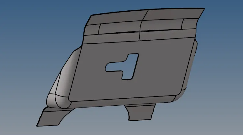
3) After deleted the solid part from latch component, remaining things were surfaces only available. Above snap is represents solid object and below snap is represents surface object.
Extracting Midsurface :
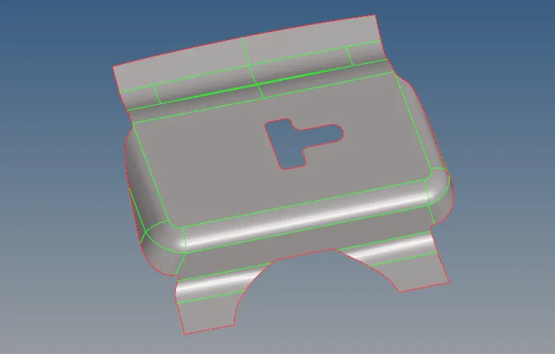
1) Basically a midsurface means creates between two surfaces, which will help us to minimize the calculating time and storage space. If the cross section area of the component is same as throughout the model bywhich means we use 'Auto Midsurface' Option under 'Mid surface' panel from " Geometry " main menu bar. In this case, a model thickness is varying constant and thickness value is 1.2 mm.
2) By using 'Auto Midsurface' option to extract the midsurface. After extracting midsurface from parent component, a midsurface looks like same as below snap.
3) Naming the extracted midsurface as per convenience for easy to reference.
Geometry Cleanup :
1) First, have to perform automatic cleanup on that particular component, after that we perform manual cleanup.
2) Make sure set the "Edit criteria" as per given values. After set the parameters values then click to proceeding for autocleanup on a component.
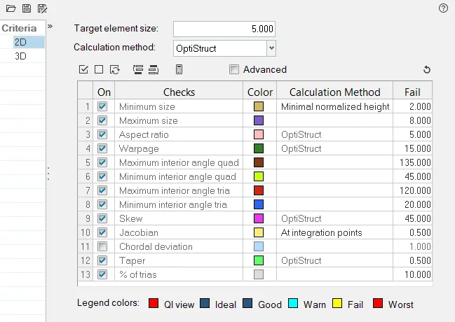
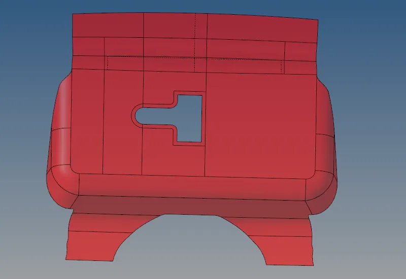
3) By using 'Auto Cleanup' option to cleanup the latch component, after that cleanup the geometry in manually by using 'Quick edit panel' option.
4) Under the 'Quick edit' panel, it have some of the sub panel were available on it. Mostly, using sub panel are 'Split surf - line', 'Toggle edge', 'Adjust/set density', 'Washer split', 'Add/Remove point' and 'Replace point'.
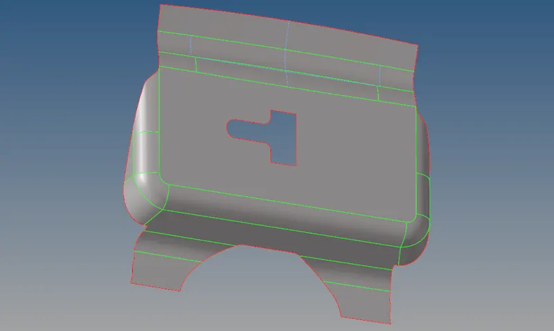
5) For manual cleanup, we have suppress any one of the line if distance between the two lines are less than the 2mm. Create a sharped edge lines additionally between some small surfaces which are helps us to increase the mesh element quality on that particular area.
6) Create a 'Washer Split' for which capturing the element properly near the cutted surfaces.
Meshing :
1) To discritize the component into infinitesimal comtrol volume, that frame is called meshing. This process is called discritization.
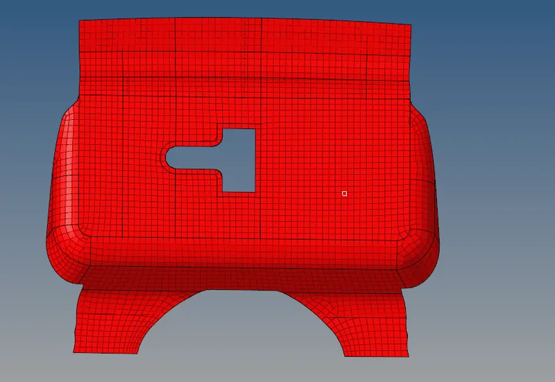
2) By using "Auto Mesh" option to generate mesh on that particular selected surface, similarly to do for all the remaining surface on a latch component. By using 5mm element size and element type is 'Quad' under the 'Size and Bias' option with that uncheck the 'Size and Skew' option and then meshing it.
3) Repetitively do the meshing operation whenever we will get the proper flow mesh and also whenever we get element are merging into surface on it.
ii) Hinge Reinforcement component :
Unselect the Latch Reinforcement component and select the one of the Hinge Reinforcement component.
Delete Solid:
1) After selecting one of the Hinge Reinforcement component, it will showing the component from hyperworks window. This component is a solid part, we need only surface for extracting the midsurface from that Hinge component. So, we has to delete the solids by using delete option.
2) Click the 'Delete option' from tool bar or else press F2 from the keyboard. Choose the 'Solid' from selector bar then selecting the solids from Hinge component and then click the 'delete option' or else click middle mouse button.
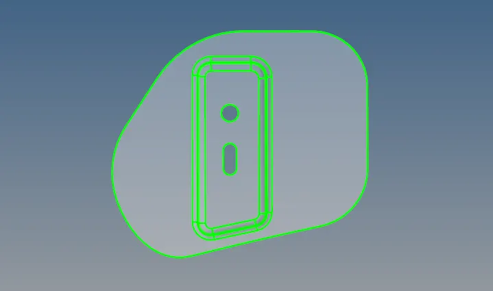
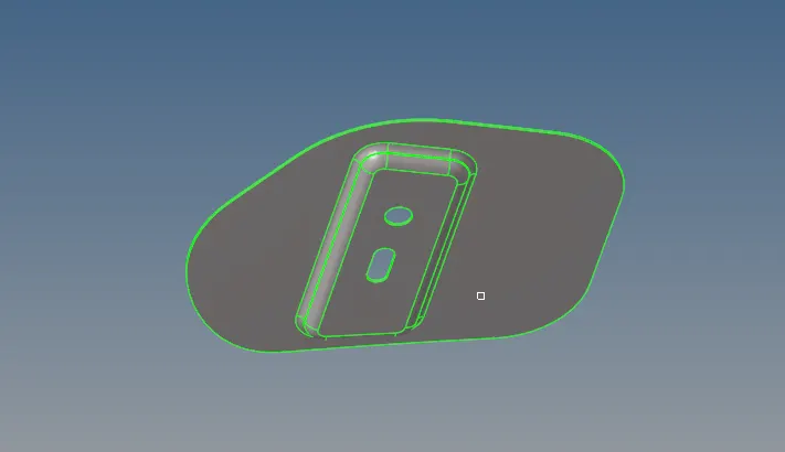
3) After deleted the solid part from parent Hinge component, remaining things were surface object only available. Above snap is represents solid object and below snap is represents surface object.
Extracting Midsurface :
1) Select the "Geometry" under the main menu panel we have option called " Midsurface" and under the midsurface option we have auto midsurface. By using " Auto Midsurface" to extract the midsurface from parent Hinge reinforcement component. Below snap is shows a mid surface for Hinge reinforcement component.
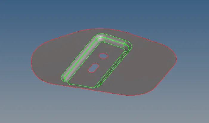
Geometry Cleanup :
1) After extracting midsurface, we have to cleanup the component for getting quality mesh. First, by using 'Auto cleanup' option to perform a automatic cleanup on a component. Before proceeding into autoclean, make sure set the "Edit criteria" as per given values.
2) Inorder to get the proper geometry cleanup, by performing manual cleanup on that particular component.
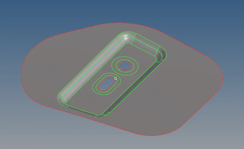
3) By performing an manual cleanup by using "Quick edit" option. In this component, mostly have to used option are called 'toggle option' to suppress or unsupress the line.
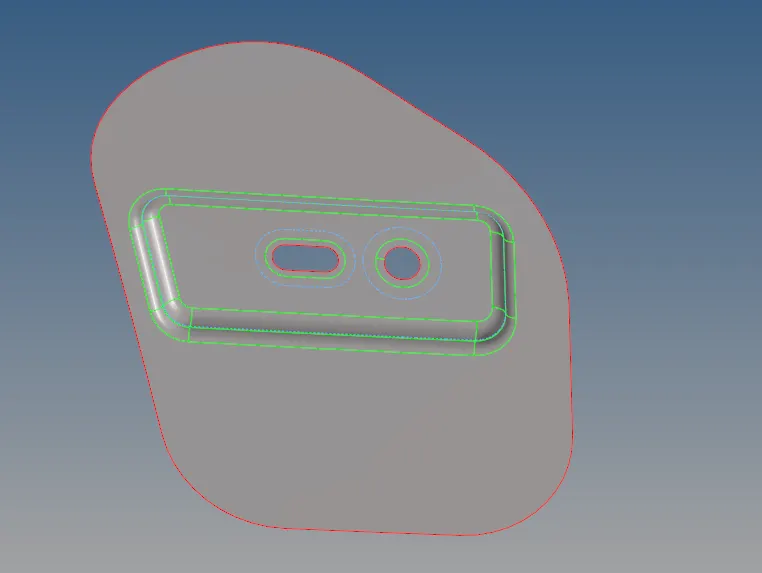
Meshing :
1) Similarly, by using element size is 5mm and element type is "Quad" to do "Auto Mesh". In this component some curves were found, we need to remesh it repetitively whenever a mesh gets proper on it. Some few rotational quads are formed due to curve surface.
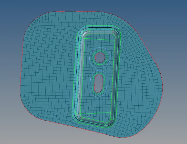
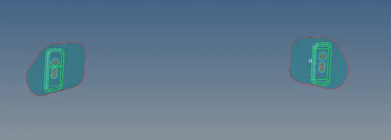
2) Meshing on right side hinge reinforcement component is completed and left side hinge is placed eqiuvalent distances from both sides about center line or axis. Both hinge are perfect symmetric component on each other.
3) By using " Reflect panel" under the "Tools" option to mirrroring the element from right hinge component to left side hinge component.
4) Open the "Reflect" option with set into element, then select the element which we want to reflect.
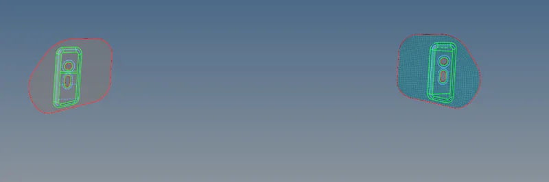
5) Duplicate the those selected element from original component element, Let's set the "Y axis" because we want to reflect about y axis.
6) Select the visible option for hood inner or outer for which select the base point at middle line of the component and then it gets reflected.

7) Below snap shows the element are reflected on a opposite hinge midsurface.
iii) Hood Outer Component :
Unselecting the all the components, except selecting the Hood outer component.
Delete Solid :
1) After selecting the Hood outer component, it will showing that component from hyperworks window. This component is a solid part, we need only surface for extracting the midsurface from that Hood outer component. So, we has to delete the solids by using delete option.
2) Click the 'Delete option' from tool bar or else press F2 from the keyboard. Choose the 'Solid' from selector bar then selecting the solid from Hood outer component and then click the 'delete option' or else click middle mouse button to the delete the solid from component.
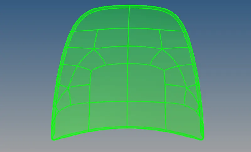
With solid :
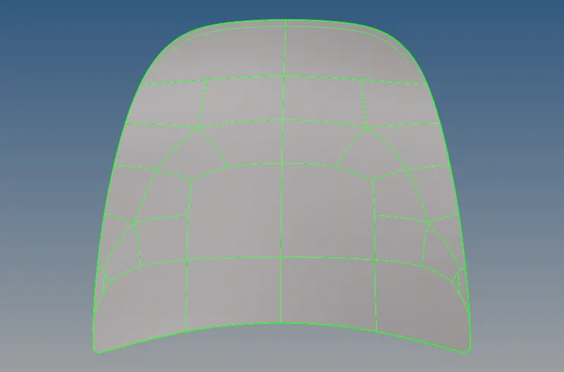
Without solid :
After deleted the solid part from Hood outer component, remaining things were surface object only available. Above snap is represents solid object and below snap is represents surface object.
Extract Midsurface :
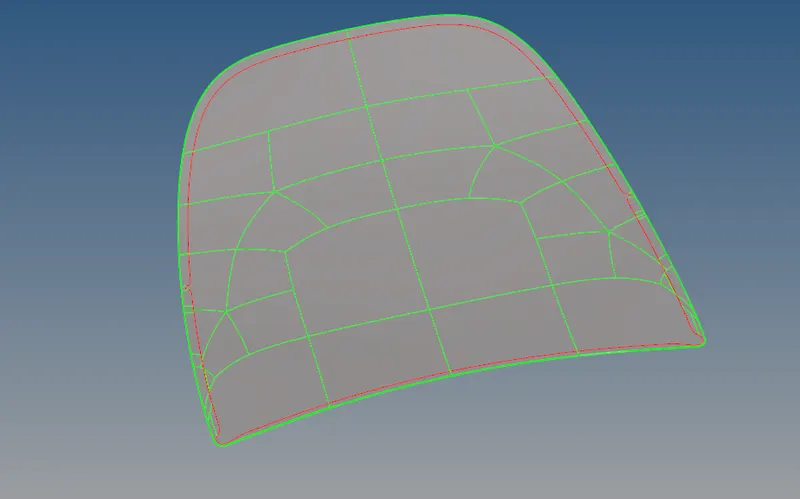
1) Select the "Geometry" under the main menu panel we have option called " Midsurface" and under the midsurface option we have 'auto midsurface' option. By using " Auto Midsurface" to extract the midsurface from parent Hood outer component. Below snap is shows a mid surface for Hood outer component.
2) After extracting a midsurface from parent component, a mid and parent surface are look sample. Because a thickness of the parent component is least.
Geometry Cleanup :
i) Auto Cleanup :
1) After extracting a midsurface, we have to perform geometry cleanup on hood outer component. First, by using an "Auto cleanup" option to cleanup the geometry. We need to cleanup the geometry in manually in some area like Hemming edges, toggling and spliting the surface for meshing.
Hemming Surface :
When by using 'auto cleanup' option, it will not properly cleanup the hemming region. So, we need cleanup those region in manually.
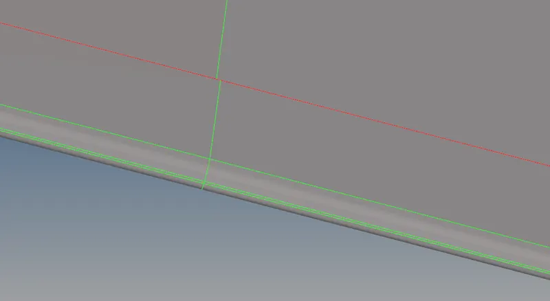
2) In auto cleanup option is missing to suppress few of the sharped edges on a surface. So, we manually suppress those unneeded sharped edge line from surface. Below snap shows a component after which completes the geometry cleanup by automatic.
ii) Manual Cleanup :
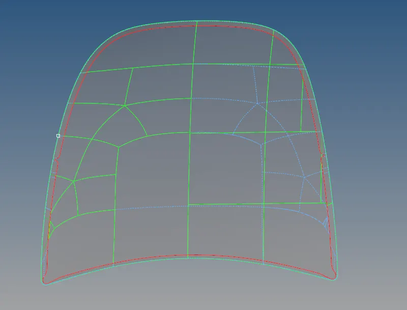
1) A outer component is looks exactly symmetrically in shape about y axis. So, we cleanup one of the side then mirroring it by using 'reflect' option
2) Supress the sharped edges at where hemmimg corners around the hood outer surface.
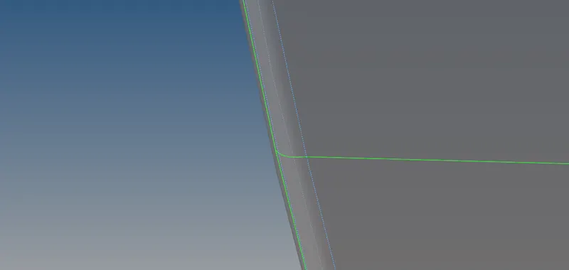
3) Supressing the sharped edge line on a surface, then create new line as per our convenience. These cleanup are helps capturing a proper mesh.
Meshing :
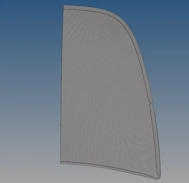
1) Go to "Auto mesh" option under the "2D" main menu panel, by using 5mm element size and element type is "QUAD". Select the any one of the surface and meshing on it and adjust the density upto whenever we get a proper element flow. Subsequently perform on remaining surface.
2) If a 'tria' element are involved from created mesh, by using "drag tria element" option under the "Element index" panel to drag out the 'tria' elements. Smooth option is helps us to smoothing the meshing. "Element optimize" option is help us to automatically optimize the element quality when we click on a element.
3) 'Place node' option is helps to move the node, a 'Split quad element' option is helps split the quad element into tria element and 'Combine tria element' option is helps to combine the two tria element into quad element.
Reflecting the elements :
1) After completion of mesh on half a component, go to " Tools" option under which we have panel called " Reflect". By use reflect option to mirroring the element from one half side to another half side.
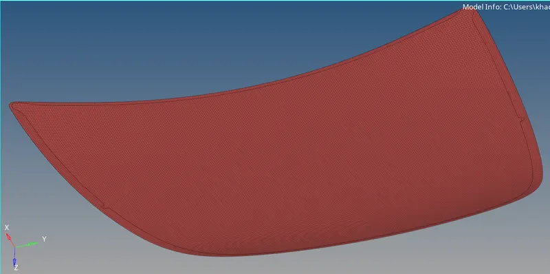
2) Go to "Reflect" option and select the elements from Hood inner component, make a duplicate elements from original component. We want to reflect the element about on Y axis and select the "Maintain Z axis direction"
3) After reflecting the elements to another half, a meshed component looks like below snap.
Elements on Hemming region :
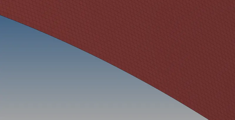
A proper geometry cleanup were helps us to getting proper hemming edge.
iv) Hood Inner Component :
Unselecting the all the components, except selecting the Hood inner component.
Delete solids :
1) After selecting the Hood inner component, it will showing the component from hyperworks window. This component is a solid part, we need only surface for extracting the midsurface from Hood inner component. So, we has to delete the solids by using delete option.
2) Click the 'Delete option' from tool bar or else press F2 from the keyboard. Choose the 'Solid' from selector bar then selecting the solid from Hinge component and then click the 'delete option' or else click middle mouse button to delete the solid from hood inner component.
With Solid :
Without Solid :
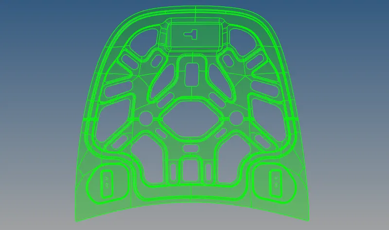
After deleted the solid part from Hood inner component, remaining things were surface object only available. Above snap is represents solid object and below snap is represents surface object.
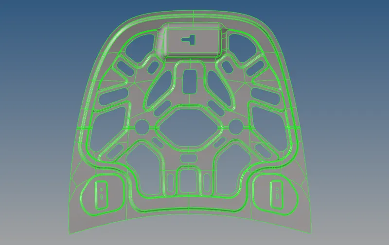
Extracting the midsurface :
1) Select the "Geometry" under the main menu panel we have option called " Midsurface" and under the midsurface option we have "auto midsurface" option. By using " Auto Midsurface" to extract the midsurface from parent Hood inner component. Below snap is shows a mid surface for Hood outer component.
2) We have different options to automatically extracting the midsurface to the component. In this case, 'Offset + Planes +Sweeps' option under the 'Extraction option' by use to extract the good mid surface.
3) After extracting the midsurface, it will looks like below sanp image.
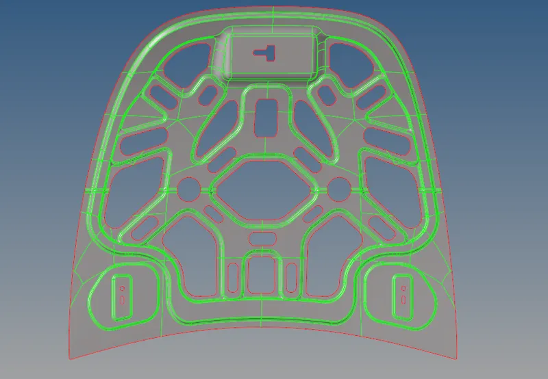
Geometry Cleanup :
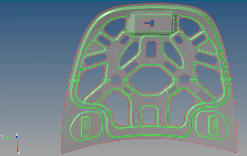
1) First, by using " Auto cleanup" option to cleanup the geometry. A autocleanup had missed some of the sharped edge lines to supress or unsupress the needed lines.
2) A midsurface is symmetrical on about the Y axis. So we need to perform a manual cleanup only on half of a portion to which creating the sharped edge lines or suppressing unneeded lines. Most of manual cleanup tools are available from "Quick edit panel"
Meshing :
1) Similarly, We follow the same meshing procedure to generate a proper element flow on a surface.Once again, it's a symmetrical in shape, so we need to do only on half of a portion. Once, we complete the mesh on it then go to reflecting the element on another half of a component about an Y axis.
2) Below image is shows 'Meshing is completed on half a portion'
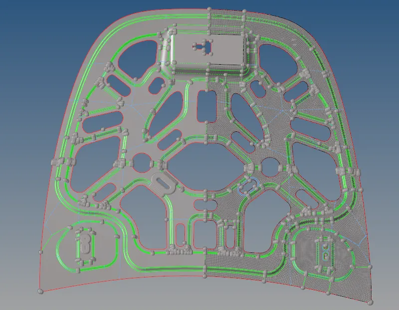
Reflect the Elements :
1) After completion of mesh on half component, go to " Tool" option under which we have panel called " Reflect". By use reflect option to mirroring the element from one half side to another half side.
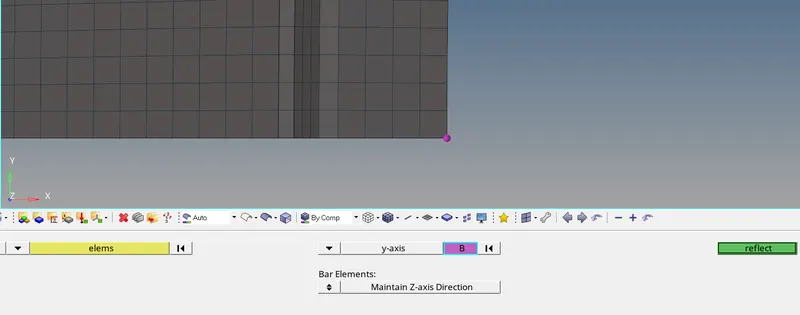
2) Go to "Reflect" option and select the elements from Hood inner component, make a duplicate elements from original component. We want to reflect the element about on Y axis and select the "Maintain Z axis direction"
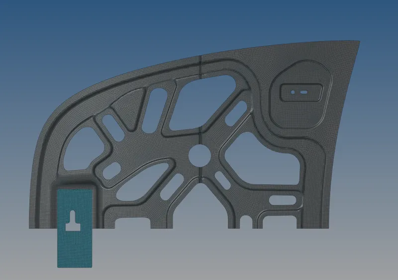
3) Selecting the elements which are needs to reflect on another half. Make a duplicate elements from selected elements
4) Select the base node at where a duplicate elements are reflected about on it.
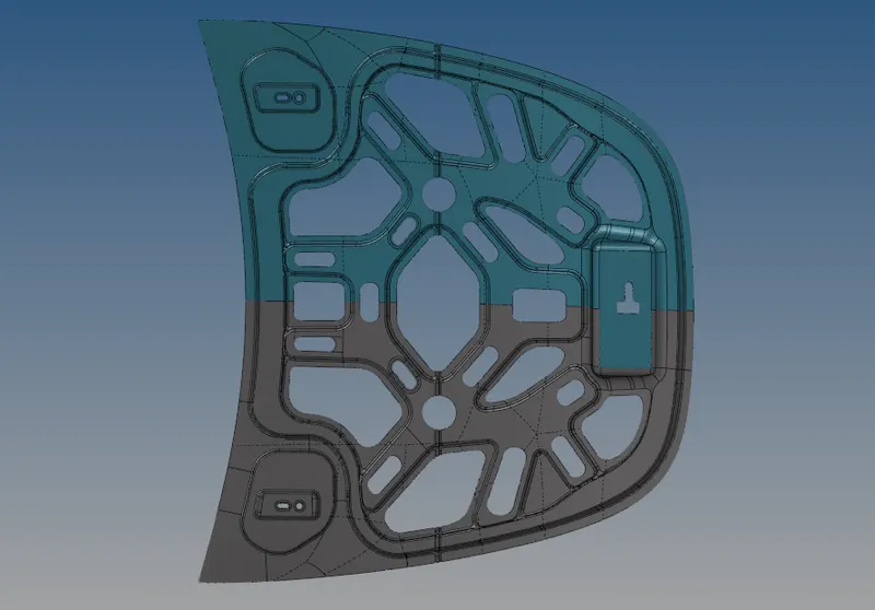
After Reflecting the elements :
Equivalence :
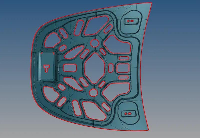
1) After reflecting the elements on a component, a free edge is found at where symmetrical line. Go to 'Tools' under main menu option we have option called 'Edges', click on it then select the respective component and then "click find edge option" to viewing the free edges between the elements.
2) Again select the respective component and by using 'equivalence' option to remove the free edge between the elements. Below snap image represents, there no 'Equivalence were found' between the elements.
RESULTS AND FINAL MODEL IMAGE :
Element Quality Checking :
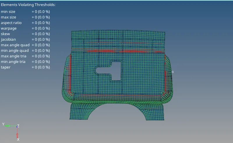
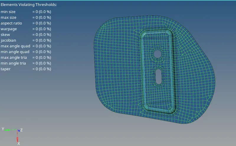
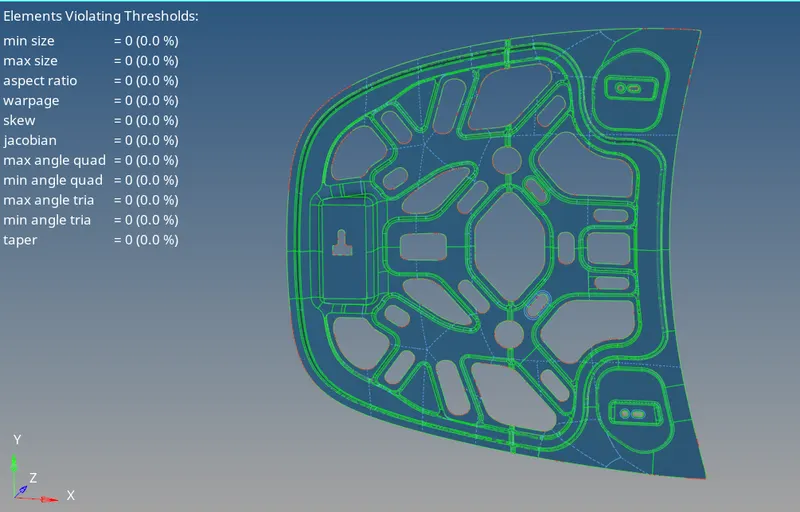
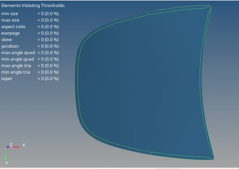
1) For checking element qualities, go to '2D' option under which we have panel called 'Element index' option. It helps us to showing the results whether a element qualities are satisfies or Not by each element parameters.
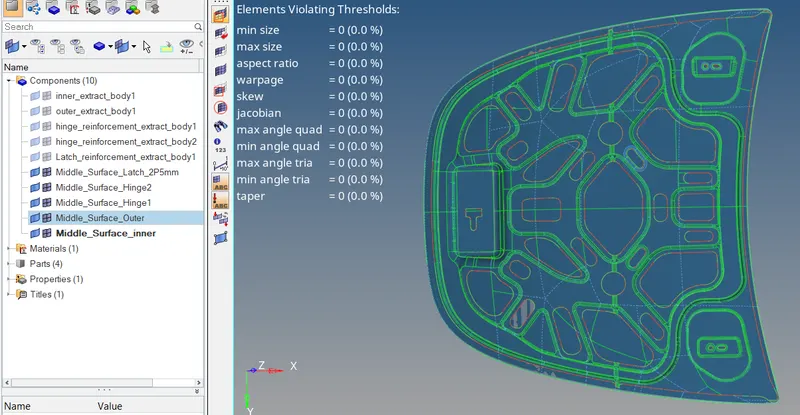
2) All component element qualities are satified all element parameters.
i) Latch component :
ii ) Hinge Component :
iii) Hood Inner component :
iv) Hood Outer Component :
Hood in all components :
FINAL MODEL IMAGE :
1) All the components are completed by the procedure of mid surface generation, both automatic and manual geometry cleanup on midsurface, Meshing or Discritization and then checking the element qualities.
2) Below image shows, all components elements are able to see from graphical window.